
User Manual
Page 4
...1.3 Unique Features 7 1.4 Motherboard Layout 11 1.5 I/O Panel 14 1.6 WiFi-802.11n Module and ASRock WiFi 2.4GHz Antenna 16 Chapter 2 Installation 17 2.1 Installing the CPU 18 2.2 Installing the CPU Fan and Heatsink 21 2.3 Installing Memory Modules (DIMM) 22 2.4 Expansion Slots (PCI and PCI Express ...Slots) 24 2.5 Jumpers Setup 25 2.6 Onboard Headers and Connectors 26 Chapter 3 Software and Utilities Operation 30 ...
...1.3 Unique Features 7 1.4 Motherboard Layout 11 1.5 I/O Panel 14 1.6 WiFi-802.11n Module and ASRock WiFi 2.4GHz Antenna 16 Chapter 2 Installation 17 2.1 Installing the CPU 18 2.2 Installing the CPU Fan and Heatsink 21 2.3 Installing Memory Modules (DIMM) 22 2.4 Expansion Slots (PCI and PCI Express ...Slots) 24 2.5 Jumpers Setup 25 2.6 Onboard Headers and Connectors 26 Chapter 3 Software and Utilities Operation 30 ...

User Manual
Page 10
...Fan Multi-Speed Control • Voltage Monitoring: +12V, +5V, +3.3V, CPU Vcore 5 English SATA3_4 connector is shared with Multilingual GUI support • ACPI 1.1 Compliance Wake Up Events • SMBIOS 2.3.1 Support • CPU, DRAM, PCH 1.05V, PCH 1.5V Voltage Multi-adjust- Z87E-ITX...Drive connector), supports NCQ, AHCI functions and Full-size mini-PCI Express modules Connector • 1 x Chassis Intrusion header • 1 x TPM header • 1 x CPU Fan connector (4-pin) • 1 x Chassis Fan connector (4-pin) • 1 x 24 pin ATX power connector • 1 x 8 pin 12V power ...
...Fan Multi-Speed Control • Voltage Monitoring: +12V, +5V, +3.3V, CPU Vcore 5 English SATA3_4 connector is shared with Multilingual GUI support • ACPI 1.1 Compliance Wake Up Events • SMBIOS 2.3.1 Support • CPU, DRAM, PCH 1.05V, PCH 1.5V Voltage Multi-adjust- Z87E-ITX...Drive connector), supports NCQ, AHCI functions and Full-size mini-PCI Express modules Connector • 1 x Chassis Intrusion header • 1 x TPM header • 1 x CPU Fan connector (4-pin) • 1 x Chassis Fan connector (4-pin) • 1 x 24 pin ATX power connector • 1 x 8 pin 12V power ...

User Manual
Page 18
... Panel Header (PANEL1) 13 Chassis Speaker Header (SPEAKER1) 14 Clear CMOS Jumper (CLRCMOS1) 15 SATA3 Connector (SATA3_1) 16 SATA3 Connector (SATA3_0) 17 SATA3 Connector (SATA3_2) 18 mini-PCI Express Slot (MINI_PCIE1) 19 WiFi-802.11n Module 20 USB 2.0 Header (USB_4_5) 21 USB 2.0 Header (USB_2_3) 22 Front Panel Audio Header (HD_AUDIO1) 23 mSATA Connector (MINI_PCIE2) Z87E-ITX English...
... Panel Header (PANEL1) 13 Chassis Speaker Header (SPEAKER1) 14 Clear CMOS Jumper (CLRCMOS1) 15 SATA3 Connector (SATA3_1) 16 SATA3 Connector (SATA3_0) 17 SATA3 Connector (SATA3_2) 18 mini-PCI Express Slot (MINI_PCIE1) 19 WiFi-802.11n Module 20 USB 2.0 Header (USB_4_5) 21 USB 2.0 Header (USB_2_3) 22 Front Panel Audio Header (HD_AUDIO1) 23 mSATA Connector (MINI_PCIE2) Z87E-ITX English...
User Manual
Page 33
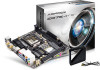
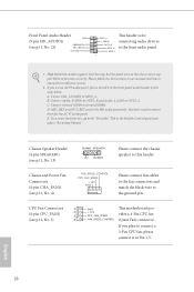
... (GND). Connect Ground (GND) to MIC2_L. CPU Fan Connectors 1 (4-pin CPU_FAN1) 2 3 (see p.11, No. 21) PRESENCE# MIC_RET OUT_RET OUT2_L J_SENSE OUT2_R MIC2_R This header is for connecting audio devices to the front panel audio header by the steps below: A. Please follow the instructions...MIC2_L 1 1. MIC_RET and OUT_RET are for the AC'97 audio panel. Chassis Speaker Header (4-pin SPEAKER1) (see p.11, No. 4) FAN_SPEED_CONTROL CPU_FAN_SPEED +12V GND Please connect fan cables to the fan connectors and match the black wire to function correctly. Connect Audio_R (RIN) to ...
... (GND). Connect Ground (GND) to MIC2_L. CPU Fan Connectors 1 (4-pin CPU_FAN1) 2 3 (see p.11, No. 21) PRESENCE# MIC_RET OUT_RET OUT2_L J_SENSE OUT2_R MIC2_R This header is for connecting audio devices to the front panel audio header by the steps below: A. Please follow the instructions...MIC2_L 1 1. MIC_RET and OUT_RET are for the AC'97 audio panel. Chassis Speaker Header (4-pin SPEAKER1) (see p.11, No. 4) FAN_SPEED_CONTROL CPU_FAN_SPEED +12V GND Please connect fan cables to the fan connectors and match the black wire to function correctly. Connect Audio_R (RIN) to ...

Quick Installation Guide
Page 5
... Panel Header (PANEL1) 13 Chassis Speaker Header (SPEAKER1) 14 Clear CMOS Jumper (CLRCMOS1) 15 SATA3 Connector (SATA3_1) 16 SATA3 Connector (SATA3_0) 17 SATA3 Connector (SATA3_2) 18 mini-PCI Express Slot (MINI_PCIE1) 19 WiFi-802.11n Module 20 USB 2.0 Header (USB_4_5) 21 USB 2.0 Header (USB_2_3) 22 Front Panel Audio Header (HD_AUDIO1) 23 mSATA Connector (MINI_PCIE2) Z87E-ITX English...
... Panel Header (PANEL1) 13 Chassis Speaker Header (SPEAKER1) 14 Clear CMOS Jumper (CLRCMOS1) 15 SATA3 Connector (SATA3_1) 16 SATA3 Connector (SATA3_0) 17 SATA3 Connector (SATA3_2) 18 mini-PCI Express Slot (MINI_PCIE1) 19 WiFi-802.11n Module 20 USB 2.0 Header (USB_4_5) 21 USB 2.0 Header (USB_2_3) 22 Front Panel Audio Header (HD_AUDIO1) 23 mSATA Connector (MINI_PCIE2) Z87E-ITX English...

Quick Installation Guide
Page 11
... modules Connector • 1 x Chassis Intrusion header • 1 x TPM header • 1 x CPU Fan connector (4-pin) • 1 x Chassis Fan connector (4-pin) • 1 x 24 pin ATX power connector • 1 x 8 pin 12V power connector (High Density Power Connector) • 1 x Front panel audio connector • 2 x USB 2.0 headers (support 4 USB 2.0 ports) • 1 x USB 3.0 header (supports 2 USB 3.0 ports) English 9 Z87E-ITX Rear Panel I/O • 1 x PS...
... modules Connector • 1 x Chassis Intrusion header • 1 x TPM header • 1 x CPU Fan connector (4-pin) • 1 x Chassis Fan connector (4-pin) • 1 x 24 pin ATX power connector • 1 x 8 pin 12V power connector (High Density Power Connector) • 1 x Front panel audio connector • 2 x USB 2.0 headers (support 4 USB 2.0 ports) • 1 x USB 3.0 header (supports 2 USB 3.0 ports) English 9 Z87E-ITX Rear Panel I/O • 1 x PS...

Quick Installation Guide
Page 30
... and match the black wire to the ground pin. If you plan to connect a 3-Pin CPU fan, please connect it to the front panel audio header by the steps below: A. D. English 28 Connect Audio_R (RIN) to OUT2_R and Audio_L (LIN) to MIC2_L. MIC2_L 1 1. Connect Mic_IN (MIC... "FrontMic" Tab in our manual and chassis manual to install your system. 2. Chassis Speaker Header (4-pin SPEAKER1) (see p.1, No. 21) PRESENCE# MIC_RET OUT_RET OUT2_L J_SENSE OUT2_R MIC2_R This header is for connecting audio devices to the front audio panel. Please follow the instructions in the ...
... and match the black wire to the ground pin. If you plan to connect a 3-Pin CPU fan, please connect it to the front panel audio header by the steps below: A. D. English 28 Connect Audio_R (RIN) to OUT2_R and Audio_L (LIN) to MIC2_L. MIC2_L 1 1. Connect Mic_IN (MIC... "FrontMic" Tab in our manual and chassis manual to install your system. 2. Chassis Speaker Header (4-pin SPEAKER1) (see p.1, No. 21) PRESENCE# MIC_RET OUT_RET OUT2_L J_SENSE OUT2_R MIC2_R This header is for connecting audio devices to the front audio panel. Please follow the instructions in the ...


