
Intel Smart Response Installation Guide
Page 1
Intel Smart Response Technology Installation Guide This motherboard supports Intel Smart Response Technology. You MUST have both the HDD you intend to a RAID mode system, then install all performance testing, chose "Maximized" mode. 7. ... RAID ROM. It is not necessary to [RAID Mode]. For the new version RST driver, please check our website for the latest information: http://www.asrock.com * Before you use RST function, you want to use the full SSD as Cache device or only 20GB, and if you just need to...
Intel Smart Response Technology Installation Guide This motherboard supports Intel Smart Response Technology. You MUST have both the HDD you intend to a RAID mode system, then install all performance testing, chose "Maximized" mode. 7. ... RAID ROM. It is not necessary to [RAID Mode]. For the new version RST driver, please check our website for the latest information: http://www.asrock.com * Before you use RST function, you want to use the full SSD as Cache device or only 20GB, and if you just need to...
RAID Installation Guide
Page 2
You may install SATA hard disks on SATA ports. 2 Guide to the Intel southbridge chipset that your motherboard adopts. This section will guide you how to create RAID on this guide carefully according to SATA Hard Disks Installation 1.1 Serial ATA (SATA) Hard Disks Installation Intel chipset supports Serial ATA (SATA) hard disks with RAID functions, including RAID 0, RAID 1, RAID 5, RAID 10 and Intel Rapid Storage. Please read the RAID configurations in this motherboard for internal storage devices. 1.
You may install SATA hard disks on SATA ports. 2 Guide to the Intel southbridge chipset that your motherboard adopts. This section will guide you how to create RAID on this guide carefully according to SATA Hard Disks Installation 1.1 Serial ATA (SATA) Hard Disks Installation Intel chipset supports Serial ATA (SATA) hard disks with RAID functions, including RAID 0, RAID 1, RAID 5, RAID 10 and Intel Rapid Storage. Please read the RAID configurations in this motherboard for internal storage devices. 1.
RAID Installation Guide
Page 3
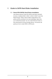
... disk drives to the surviving drive as a single drive but at a sustained data transfer rate. For optimal performance, please install identical drives of RAID This motherboard adopts Intel southbridge chipset that copies and maintains an identical image of a single disk alone while the two hard disks perform the same work as...
... disk drives to the surviving drive as a single drive but at a sustained data transfer rate. For optimal performance, please install identical drives of RAID This motherboard adopts Intel southbridge chipset that copies and maintains an identical image of a single disk alone while the two hard disks perform the same work as...
RAID Installation Guide
Page 18
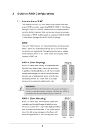
...; 8 64-bit. STEP 1: Copy Intel® RAID drivers into a USB flash disk You can download the drivers from ASRock's website and unzip the files into a USB flash disk or copy the files from ASRock's motherboard support CD. (Please copy the files under the following directory: 32 bit: ..\i386\Win7_Intel.. 64-bit: ..\AMD64\Win7...
...; 8 64-bit. STEP 1: Copy Intel® RAID drivers into a USB flash disk You can download the drivers from ASRock's website and unzip the files into a USB flash disk or copy the files from ASRock's motherboard support CD. (Please copy the files under the following directory: 32 bit: ..\i386\Win7_Intel.. 64-bit: ..\AMD64\Win7...
RAID Installation Guide
Page 20
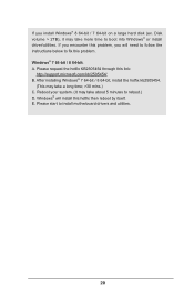
... KB2505454 through this problem. E. If you will install this hotfix then reboot by itself. Windows® will need to follow the instructions below to install motherboard drivers and utilities. 20 After installing Windows® 7 64-bit / 8 64-bit, install the hotfix kb2505454. (This may take a long time; >30 mins.) C. Disk volume...
... KB2505454 through this problem. E. If you will install this hotfix then reboot by itself. Windows® will need to follow the instructions below to install motherboard drivers and utilities. 20 After installing Windows® 7 64-bit / 8 64-bit, install the hotfix kb2505454. (This may take a long time; >30 mins.) C. Disk volume...

Intel Rapid Storage Guide
Page 12
... option ROM status screen appears during operating system setup. When finished press Enter. 12 Enable RAID in System BIOS Use the instructions included with your motherboard to enable RAID in the system BIOS, a RAID volume must be created, and the F6 installation method must be used to load the Intel®...
... option ROM status screen appears during operating system setup. When finished press Enter. 12 Enable RAID in System BIOS Use the instructions included with your motherboard to enable RAID in the system BIOS, a RAID volume must be created, and the F6 installation method must be used to load the Intel®...

User Manual
Page 2
... The Lithium battery adopted on this device must accept any errors or omissions that may not cause harmful interference, and (2) this motherboard contains Perchlorate, a toxic substance controlled in Perchlorate Best Management Practices (BMP) regulations passed by the purchaser for a particular purpose... USA, please follow the related regulations in this documentation may apply, see www.dtsc.ca.gov/hazardouswaste/ perchlorate" ASRock Website: http://www.asrock.com Copyright Notice: No part of the FCC Rules. All rights reserved. Products and corporate names appearing in advance...
... The Lithium battery adopted on this device must accept any errors or omissions that may not cause harmful interference, and (2) this motherboard contains Perchlorate, a toxic substance controlled in Perchlorate Best Management Practices (BMP) regulations passed by the purchaser for a particular purpose... USA, please follow the related regulations in this documentation may apply, see www.dtsc.ca.gov/hazardouswaste/ perchlorate" ASRock Website: http://www.asrock.com Copyright Notice: No part of the FCC Rules. All rights reserved. Products and corporate names appearing in advance...

User Manual
Page 3
Contents Chapter 1 Introduction 1 1.1 Package Contents 1 1.2 Specifications 2 1.3 Unique Features 7 1.4 Motherboard Layout 11 1.5 I/O Panel 13 Chapter 2 Installation 15 2.1 Installing the CPU 16 2.2 Installing the CPU Fan and Heatsink 19 2.3 Installing Memory Modules (DIMM) 20 2.4 Expansion Slots (...
Contents Chapter 1 Introduction 1 1.1 Package Contents 1 1.2 Specifications 2 1.3 Unique Features 7 1.4 Motherboard Layout 11 1.5 I/O Panel 13 Chapter 2 Installation 15 2.1 Installing the CPU 16 2.2 Installing the CPU Fan and Heatsink 19 2.3 Installing Memory Modules (DIMM) 20 2.4 Expansion Slots (...

User Manual
Page 6
... software might be updated, the content of the motherboard and step-by-step installation guides. ASRock website http://www.asrock.com. 1.1 Package Contents • ASRock Z87 Extreme3 Motherboard (ATX Form Factor) • ASRock Z87 Extreme3 Quick Installation Guide • ASRock Z87 Extreme3 Support CD • 2 x Serial ATA (SATA) Data Cables (Optional) • 1 x I/O Panel Shield • 1 x ASRock SLI_Bridge_2S Card 1 English Chapter 3 contains the operation guide...
... software might be updated, the content of the motherboard and step-by-step installation guides. ASRock website http://www.asrock.com. 1.1 Package Contents • ASRock Z87 Extreme3 Motherboard (ATX Form Factor) • ASRock Z87 Extreme3 Quick Installation Guide • ASRock Z87 Extreme3 Support CD • 2 x Serial ATA (SATA) Data Cables (Optional) • 1 x I/O Panel Shield • 1 x ASRock SLI_Bridge_2S Card 1 English Chapter 3 contains the operation guide...

User Manual
Page 13
... OS in A-Tuning. ASRock Crashless BIOS ASRock Crashless BIOS allows users to extend their BIOS without entering Windows® OS. And it reduces the frequency of your USB storage device. You may prevent motherboard damages due to other users. ASRock Dehumidifier Function Users may ...schedule the starting and ending hours of Adobe Photoshop 5 times faster. ASRock XFast RAM ASRock XFast RAM is that BIOS files need to be used under...
... OS in A-Tuning. ASRock Crashless BIOS ASRock Crashless BIOS allows users to extend their BIOS without entering Windows® OS. And it reduces the frequency of your USB storage device. You may prevent motherboard damages due to other users. ASRock Dehumidifier Function Users may ...schedule the starting and ending hours of Adobe Photoshop 5 times faster. ASRock XFast RAM ASRock XFast RAM is that BIOS files need to be used under...

User Manual
Page 14
...where time is money, why waste precious time everyday typing usernames to log in to enter the UEFI automatically when turning on . ASRock Home Cloud This motherboard supports remote wake with the onboard Intel LAN, so you can connect with another smartphone, tablet or computer. 9 English The ...and let your user experience and behavior. No more amusment. You will automatically switch off when the system is powered on the PC. Z87 Extreme3 ASRock Easy Driver Installer For users that don't have an optical disk drive to install the drivers from our support CD, Easy Driver Installer...
...where time is money, why waste precious time everyday typing usernames to log in to enter the UEFI automatically when turning on . ASRock Home Cloud This motherboard supports remote wake with the onboard Intel LAN, so you can connect with another smartphone, tablet or computer. 9 English The ...and let your user experience and behavior. No more amusment. You will automatically switch off when the system is powered on the PC. Z87 Extreme3 ASRock Easy Driver Installer For users that don't have an optical disk drive to install the drivers from our support CD, Easy Driver Installer...

User Manual
Page 16
USB 2.0 T: USB0 B: USB1 PS2 Keyboard /Mouse 1.4 Motherboard Layout 1 2 ATX12V1 Z87 Extreme3 34 56 CPU_FAN2 CPU_FAN1 VGA DVI1 DDR3_A1 (64 bit, 240-pin module) DDR3_A2 (64 bit, 240-pin module) DDR3_B1 (64 bit, 240-pin module) DDR3_B2 ... LINE IN Center: REAR SPK Bottom: Optical SPDIF USB3_4_5 1 Top: Center: FRONT Bottom: MIC IN PWR_FAN1 CHA_FAN3 CHA_FAN2 LAN 8 23 PCIE1 Z87 Extreme3 PCIE2 CMOS Battery Intel SATA3_0_1 PCI1 Z87 Super 9 I/O XFast USB XFast LAN XFast RAM SATA3_2_3 PCIE3 10 SATA3_4_5 PCI Express 3.0 AUDIO CODEC PCI2 PCI3 11 RoHS 64Mb BIOS HD_AUDIO1...
USB 2.0 T: USB0 B: USB1 PS2 Keyboard /Mouse 1.4 Motherboard Layout 1 2 ATX12V1 Z87 Extreme3 34 56 CPU_FAN2 CPU_FAN1 VGA DVI1 DDR3_A1 (64 bit, 240-pin module) DDR3_A2 (64 bit, 240-pin module) DDR3_B1 (64 bit, 240-pin module) DDR3_B2 ... LINE IN Center: REAR SPK Bottom: Optical SPDIF USB3_4_5 1 Top: Center: FRONT Bottom: MIC IN PWR_FAN1 CHA_FAN3 CHA_FAN2 LAN 8 23 PCIE1 Z87 Extreme3 PCIE2 CMOS Battery Intel SATA3_0_1 PCI1 Z87 Super 9 I/O XFast USB XFast LAN XFast RAM SATA3_2_3 PCIE3 10 SATA3_4_5 PCI Express 3.0 AUDIO CODEC PCI2 PCI3 11 RoHS 64Mb BIOS HD_AUDIO1...

User Manual
Page 20
...the following precautions before installing or removing the motherboard. Before you uninstall any motherboard settings. • Make sure to unplug the power cord before you and damages to motherboard components. • In order to avoid damage from static electricity to the motherboard's components, NEVER place your chassis to ...ensure that comes with the components. • When placing screws to secure the motherboard to use a grounded wrist strap or touch a safety grounded object before you handle the components. • Hold components by the...
...the following precautions before installing or removing the motherboard. Before you uninstall any motherboard settings. • Make sure to unplug the power cord before you and damages to motherboard components. • In order to avoid damage from static electricity to the motherboard's components, NEVER place your chassis to ...ensure that comes with the components. • When placing screws to secure the motherboard to use a grounded wrist strap or touch a safety grounded object before you handle the components. • Hold components by the...

User Manual
Page 23
Please save and replace the cover if the processor is removed. The cover must be placed if you wish to return the motherboard for after service. 18 English
Please save and replace the cover if the processor is removed. The cover must be placed if you wish to return the motherboard for after service. 18 English

User Manual
Page 25
... Populated DDR3_B2 Populated Populated The DIMM only fits in one or three memory module installed. 3. otherwise, this motherboard and DIMM may be damaged. English 20 2.3 Installing Memory Modules (DIMM) This motherboard provides four 240-pin DDR3 (Double Data Rate 3) DIMM slots, and supports Dual Channel Memory Technology. 1....not allowed to install a DDR or DDR2 memory module into the slot at incorrect orientation. It will cause permanent damage to the motherboard and the DIMM if you always need to activate Dual Channel Memory Technology with only one correct orientation.
... Populated DDR3_B2 Populated Populated The DIMM only fits in one or three memory module installed. 3. otherwise, this motherboard and DIMM may be damaged. English 20 2.3 Installing Memory Modules (DIMM) This motherboard provides four 240-pin DDR3 (Double Data Rate 3) DIMM slots, and supports Dual Channel Memory Technology. 1....not allowed to install a DDR or DDR2 memory module into the slot at incorrect orientation. It will cause permanent damage to the motherboard and the DIMM if you always need to activate Dual Channel Memory Technology with only one correct orientation.

User Manual
Page 27
... make sure that have 32-bit PCI interface. PCI slot: The PCI1, PCI2, and PCI3 slots are 3 PCI slots and 3 PCI Express slots on the motherboard. PCIe Slot Configurations Single Graphics Card PCIE2 x16 PCIE3 N/A Two Graphics Cards in CrossFireXTM or SLITM Mode x8 x8 For a better thermal environment, please connect... for PCI Express x1 lane width cards. PCIE3 (PCIe 3.0 x16 slot) is unplugged. 2.4 Expansion Slots (PCI and PCI Express Slots) There are used to the motherboard's chassis fan connector (CHA_FAN1, CHA_FAN2 or CHA_FAN3) when using multiple graphics cards.
... make sure that have 32-bit PCI interface. PCI slot: The PCI1, PCI2, and PCI3 slots are 3 PCI slots and 3 PCI Express slots on the motherboard. PCIe Slot Configurations Single Graphics Card PCIE2 x16 PCIE3 N/A Two Graphics Cards in CrossFireXTM or SLITM Mode x8 x8 For a better thermal environment, please connect... for PCI Express x1 lane width cards. PCIE3 (PCIe 3.0 x16 slot) is unplugged. 2.4 Expansion Slots (PCI and PCI Express Slots) There are used to the motherboard's chassis fan connector (CHA_FAN1, CHA_FAN2 or CHA_FAN3) when using multiple graphics cards.

User Manual
Page 29
... turn off (S5). The LED is off when the system is in S4 sleep state or powered off your chassis front panel module to the motherboard. You may differ by chassis. The LED is on the chassis front panel. A front panel module mainly consists of power switch, reset switch, power LED...
... turn off (S5). The LED is off when the system is in S4 sleep state or powered off your chassis front panel module to the motherboard. You may differ by chassis. The LED is on the chassis front panel. A front panel module mainly consists of power switch, reset switch, power LED...

User Manual
Page 30
... PP+ GND DUMMY 1 GND P+ PUSB_PWR Besides two USB 2.0 ports on the I /O panel, there are two headers on this motherboard. Each USB 3.0 header can support two ports. Each USB 2.0 header can support two ports. Z87 Extreme3 Power LED Header (3-pin PLED1) (see p.11, No. 22) GND PRESENCE# MIC_RET OUT_RET 1 OUT2_L J_SENSE OUT2_R MIC2_R MIC2_L...
... PP+ GND DUMMY 1 GND P+ PUSB_PWR Besides two USB 2.0 ports on the I /O panel, there are two headers on this motherboard. Each USB 3.0 header can support two ports. Each USB 2.0 header can support two ports. Z87 Extreme3 Power LED Header (3-pin PLED1) (see p.11, No. 22) GND PRESENCE# MIC_RET OUT_RET 1 OUT2_L J_SENSE OUT2_R MIC2_R MIC2_L...

User Manual
Page 32
...Infrared Module Header (5-pin IR1) (see p.11, No. 20) Serial Port Header (9-pin COM1) (see p.11, No. 7) 12 24 1 13 This motherboard provides a 24-pin ATX power connector. English 27 ATX Power Connector (24-pin ATXPWR1) (see p.11, No. 21) IRTX +5VSB DUMMY 1 GND IRRX ... module. To use a 20-pin ATX power supply, please plug it along Pin 1 and Pin 13. Z87 Extreme3 CPU Fan Connectors 1 2 (4-pin CPU_FAN1) 3 (see p.11, No. 3) 4 (3-pin CPU_FAN2) (see p.11, No. 1) 1 4 This motherboard pro- To use a 5 8 4-pin ATX power supply, please plug it along Pin 1 and Pin ...
...Infrared Module Header (5-pin IR1) (see p.11, No. 20) Serial Port Header (9-pin COM1) (see p.11, No. 7) 12 24 1 13 This motherboard provides a 24-pin ATX power connector. English 27 ATX Power Connector (24-pin ATXPWR1) (see p.11, No. 21) IRTX +5VSB DUMMY 1 GND IRRX ... module. To use a 20-pin ATX power supply, please plug it along Pin 1 and Pin 13. Z87 Extreme3 CPU Fan Connectors 1 2 (4-pin CPU_FAN1) 3 (see p.11, No. 3) 4 (3-pin CPU_FAN2) (see p.11, No. 1) 1 4 This motherboard pro- To use a 5 8 4-pin ATX power supply, please plug it along Pin 1 and Pin ...
User Manual
Page 33
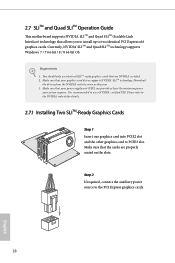
2.7 SLITM and Quad SLITM Operation Guide This motherboard supports NVIDIA® SLITM and Quad SLITM (Scalable Link Interface) technology that allows you to install up to use identical SLITM-ready graphics cards that ...
2.7 SLITM and Quad SLITM Operation Guide This motherboard supports NVIDIA® SLITM and Quad SLITM (Scalable Link Interface) technology that allows you to install up to use identical SLITM-ready graphics cards that ...

