
Software/BIOS Setup Guide
Page 3
... 2.2 ASRock Live Update & APP Shop 7 2.2.1 Installing ASRock Live Update & APP Shop 7 2.2.2 UI Overview 8 2.2.3 Apps 9 2.2.4 BIOS & Drivers 12 2.2.5 Setting 13 2.3 ASRock Motherboard Utility (A-Tuning) 14 2.3.1 Installing ASRock Motherboard Utility (A-Tuning) 14 2.3.2 Using ASRock Motherboard Utility (A-Tuning) 14 2.4 ASRock Motherboard Utility (Phantom Gaming Tuning) 17 2.4.1 Installing ASRock Motherboard Utility (Phantom Gaming Tuning) 17 2.4.2 Using ASRock Motherboard Utility (Phantom Gaming Tuning) 17 2.5 ASRock Polychrome SYNC 20 2.5.1 Connecting the LED Strip...
... 2.2 ASRock Live Update & APP Shop 7 2.2.1 Installing ASRock Live Update & APP Shop 7 2.2.2 UI Overview 8 2.2.3 Apps 9 2.2.4 BIOS & Drivers 12 2.2.5 Setting 13 2.3 ASRock Motherboard Utility (A-Tuning) 14 2.3.1 Installing ASRock Motherboard Utility (A-Tuning) 14 2.3.2 Using ASRock Motherboard Utility (A-Tuning) 14 2.4 ASRock Motherboard Utility (Phantom Gaming Tuning) 17 2.4.1 Installing ASRock Motherboard Utility (Phantom Gaming Tuning) 17 2.4.2 Using ASRock Motherboard Utility (Phantom Gaming Tuning) 17 2.5 ASRock Polychrome SYNC 20 2.5.1 Connecting the LED Strip...

Software/BIOS Setup Guide
Page 5
...; Auto Driver Installer (ADI) • ASRock Live Update & APP Shop • ASRock Motherboard Utility (A-Tuning) • ASRock Motherboard Utility (Phantom Gaming Tuning) • ASRock Polychrome SYNC • Nahimic Audio BIOS Setup Guide • UEFI Setup Utility Because the motherboard specifications and the software might be updated, the content of this documentation, Chapter 1 gives an overview of this manual are using. If you require technical support related to this motherboard, please visit our website for specific information about the model...
...; Auto Driver Installer (ADI) • ASRock Live Update & APP Shop • ASRock Motherboard Utility (A-Tuning) • ASRock Motherboard Utility (Phantom Gaming Tuning) • ASRock Polychrome SYNC • Nahimic Audio BIOS Setup Guide • UEFI Setup Utility Because the motherboard specifications and the software might be updated, the content of this documentation, Chapter 1 gives an overview of this manual are using. If you require technical support related to this motherboard, please visit our website for specific information about the model...

Software/BIOS Setup Guide
Page 7
... change the setting in the BIOS setting. The item is no need to [Enabled]. Select "No" to install Auto Driver Installer. therefore, for using the Auto Driver Installer. An available Internet connection is a prerequisite for the first-time users, there is enabled by default; Intel Z790/H770/B760 Series Step 2 Boot into the system without Internet, the Auto Driver Installer won't appear. Step 3 When it's completed, you will see the Auto Driver Installer icon on your screen...
... change the setting in the BIOS setting. The item is no need to [Enabled]. Select "No" to install Auto Driver Installer. therefore, for using the Auto Driver Installer. An available Internet connection is a prerequisite for the first-time users, there is enabled by default; Intel Z790/H770/B760 Series Step 2 Boot into the system without Internet, the Auto Driver Installer won't appear. Step 3 When it's completed, you will see the Auto Driver Installer icon on your screen...

Software/BIOS Setup Guide
Page 9
... Auto Driver Installer will be removed. Step 6 Once all drivers are successfully installed, a message pops up saying, "During installation, your computer. Intel Z790/H770/B760 Series Step 5 A messages pops up saying, "Installation has been successfully completed! For further drivers and utilities, please visit ASRock's website." If you would like to run the application again, please go to the "Tool" menu in the BIOS setting, and set the "Auto Driver Installer...
... Auto Driver Installer will be removed. Step 6 Once all drivers are successfully installed, a message pops up saying, "During installation, your computer. Intel Z790/H770/B760 Series Step 5 A messages pops up saying, "Installation has been successfully completed! For further drivers and utilities, please visit ASRock's website." If you would like to run the application again, please go to the "Tool" menu in the BIOS setting, and set the "Auto Driver Installer...

Software/BIOS Setup Guide
Page 29
... for instructions. 3.1.1 Entering BIOS Setup You may cause system instability, mulfunction or boot failure. This setup guide explains how to use the UEFI SETUP UTILITY to different BIOS release versions or CPU installed. The screenshots in the CMOS. Intel Z790/H770/B760 Series Chapter 3 UEFI SETUP UTILITY 3.1 Introduction ASRock UEFI (Unified Extensible Firmware Interface) is turned off and then back on . This BIOS utility can perform the Power-On Self-Test (POST) during system startup, record hardware parameters of the motherboard...
... for instructions. 3.1.1 Entering BIOS Setup You may cause system instability, mulfunction or boot failure. This setup guide explains how to use the UEFI SETUP UTILITY to different BIOS release versions or CPU installed. The screenshots in the CMOS. Intel Z790/H770/B760 Series Chapter 3 UEFI SETUP UTILITY 3.1 Introduction ASRock UEFI (Unified Extensible Firmware Interface) is turned off and then back on . This BIOS utility can perform the Power-On Self-Test (POST) during system startup, record hardware parameters of the motherboard...

Software/BIOS Setup Guide
Page 37
...out. Configuration options: [Enabled] [Disabled] Intel Turbo Boost Technology Intel Turbo Boost Technology enables the processor to switch between multiple frequencies and voltage points for better power saving and heat dissipation. Configuration options: [Enabled] [Disabled] 33 Intel SpeedStep Technology Intel SpeedStep technology allows processors to run above its base operating frequency when the operating system requests the highest performance state. To get the best support for hardware controlled P-states. Configuration options: [Enabled] [Disabled] FLL Overclock Mode Select...
...out. Configuration options: [Enabled] [Disabled] Intel Turbo Boost Technology Intel Turbo Boost Technology enables the processor to switch between multiple frequencies and voltage points for better power saving and heat dissipation. Configuration options: [Enabled] [Disabled] 33 Intel SpeedStep Technology Intel SpeedStep technology allows processors to run above its base operating frequency when the operating system requests the highest performance state. To get the best support for hardware controlled P-states. Configuration options: [Enabled] [Disabled] FLL Overclock Mode Select...

Software/BIOS Setup Guide
Page 38
Intel Turbo Boost Max Technology 3.0 Allows you to enable or disable the Intel Base Power Limit Settings. Load Intel Base Power Limit Settings Allows you to set CPU Tj Max to disable it is higher than TDP for overclocking. When the limit is enabled, the user will use on supported products. Processors supporting the ITBMT 3.0 feature contain at least one processor core whose maximum ratio is enabled, the power limit and current limit will be...
Intel Turbo Boost Max Technology 3.0 Allows you to enable or disable the Intel Base Power Limit Settings. Load Intel Base Power Limit Settings Allows you to set CPU Tj Max to disable it is higher than TDP for overclocking. When the limit is enabled, the user will use on supported products. Processors supporting the ITBMT 3.0 feature contain at least one processor core whose maximum ratio is enabled, the power limit and current limit will be...

Software/BIOS Setup Guide
Page 65
...'ve installed a graphics card on your virtual machine monitor better utilize hardware by improving application compatibility and reliability, and providing additional levels of the system supports 64-bit PCI decoding). This is disabled automatically when Aperture Size is set to select a primary VGA. Configuration options: [Enabled] [Disabled] C.A.M (Clever Access Memory) If system has Resizable BAR capable PCIe Devices, use this option to enable or disable Resizable BAR support (only of manageability, security, isolation, and I /O helps your motherboard.) Above...
...'ve installed a graphics card on your virtual machine monitor better utilize hardware by improving application compatibility and reliability, and providing additional levels of the system supports 64-bit PCI decoding). This is disabled automatically when Aperture Size is set to select a primary VGA. Configuration options: [Enabled] [Disabled] C.A.M (Clever Access Memory) If system has Resizable BAR capable PCIe Devices, use this option to enable or disable Resizable BAR support (only of manageability, security, isolation, and I /O helps your motherboard.) Above...

Software/BIOS Setup Guide
Page 66
... PCIE2 Slot Link Speed. Configuration options: [Auto] [Gen1] [Gen2] [Gen3] [Gen4] (Options vary depending on your motherboard.) PCI Express Native Control Select Enabled for overclocking. Auto mode is optimizing for enhanced PCI Express power saving in OS. Auto mode is optimizing for all CPU downstream devices. Configuration options: [Enabled] [Disabled] PCIE ASPM Support This option controls the ASPM support for overclocking. Configuration options: [Disabled] [L0s] [L1] [L0sL1] PCH PCIE ASPM Support This option controls the ASPM support for overclocking. Auto mode is...
... PCIE2 Slot Link Speed. Configuration options: [Auto] [Gen1] [Gen2] [Gen3] [Gen4] (Options vary depending on your motherboard.) PCI Express Native Control Select Enabled for overclocking. Auto mode is optimizing for enhanced PCI Express power saving in OS. Auto mode is optimizing for all CPU downstream devices. Configuration options: [Enabled] [Disabled] PCIE ASPM Support This option controls the ASPM support for overclocking. Configuration options: [Disabled] [L0s] [L1] [L0sL1] PCH PCIE ASPM Support This option controls the ASPM support for overclocking. Auto mode is...

Software/BIOS Setup Guide
Page 67
...Disabled] Onboard HD Audio Allows you to enable or disable the onboard HD audio controller. Configuration options: [Enabled] [Disabled] Share Memory Allows you to enable or disable Onboard LAN. Select [Enabled] to the integrated graphics processor when the system boots up. Configuration options: [Auto] [32M] [64M] [128M] [256M] [512M] [1024M] Options vary depending on the memory you to enable or disable Onboard LAN. Configuration options: [Enabled] [Disabled] Intel(R) Ethernet Connection I226-V Allows you to configure the size of memory that is installed. Configuration options...
...Disabled] Onboard HD Audio Allows you to enable or disable the onboard HD audio controller. Configuration options: [Enabled] [Disabled] Share Memory Allows you to enable or disable Onboard LAN. Select [Enabled] to the integrated graphics processor when the system boots up. Configuration options: [Auto] [32M] [64M] [128M] [256M] [512M] [1024M] Options vary depending on the memory you to enable or disable Onboard LAN. Configuration options: [Enabled] [Disabled] Intel(R) Ethernet Connection I226-V Allows you to configure the size of memory that is installed. Configuration options...

Software/BIOS Setup Guide
Page 68
...power recovers. [Power On] sets the system to start to restore Onboard LED default value. Configuration options: [Enabled] [Disabled] Restore Onboard LED Default Allows you 've installed a graphics card on AC/Power Loss Allows you to enable or disable the onboard WAN device. Configuration options: [Auto] [Enabled] [Disabled] Front Panel Allows you to select Front Panel type. [HD] sets the front panel audio connector mode to high definition audio. [AC 97] sets the front panel audio connector mode to legacy AC'97.] Onboard HDMI HD Audio Allows you to configure deep sleep mode for power...
...power recovers. [Power On] sets the system to start to restore Onboard LED default value. Configuration options: [Enabled] [Disabled] Restore Onboard LED Default Allows you 've installed a graphics card on AC/Power Loss Allows you to enable or disable the onboard WAN device. Configuration options: [Auto] [Enabled] [Disabled] Front Panel Allows you to select Front Panel type. [HD] sets the front panel audio connector mode to high definition audio. [AC 97] sets the front panel audio connector mode to legacy AC'97.] Onboard HDMI HD Audio Allows you to configure deep sleep mode for power...

Software/BIOS Setup Guide
Page 71
... map or unmap this Root Port to enable or disable the Intel VMD controller. Configuration options: [Enabled] [Disabled] Root Port BDF details Displays the Root Port BDF details. 67 Enable VMD Controller Allows you to [Enabled]. This following items appear when it is set to enable or disable the VMD Global Mapping. Configuration options: [Enabled] [Disabled] VMD Configuration Press [Enter] to view the followings items for computer hard disk drives to [Disabled]. This item is allowed to...
... map or unmap this Root Port to enable or disable the Intel VMD controller. Configuration options: [Enabled] [Disabled] Root Port BDF details Displays the Root Port BDF details. 67 Enable VMD Controller Allows you to [Enabled]. This following items appear when it is set to enable or disable the VMD Global Mapping. Configuration options: [Enabled] [Disabled] VMD Configuration Press [Enter] to view the followings items for computer hard disk drives to [Disabled]. This item is allowed to...

Software/BIOS Setup Guide
Page 72
... present behind Thunderbolt. Configuration options: [Enabled] [Disabled] Thunderbolt Boot Support The item appears when "Discrete Thunderbolt(TM) Support" is enabled. [Enabled] sets to boot from Usb devices which are present behind Thunderbolt. [Disabled] sets to disallow booting from Bootable devices which are present behind Thunderbolt. 68 Thunderbolt Usb Support The item appears when "Discrete Thunderbolt(TM) Support" is enabled. [Enabled] sets to boot from Usb devices which are present behind Thunderbolt. [Disabled] sets to enable or disable the Discrete Thunderbolt...
... present behind Thunderbolt. Configuration options: [Enabled] [Disabled] Thunderbolt Boot Support The item appears when "Discrete Thunderbolt(TM) Support" is enabled. [Enabled] sets to boot from Usb devices which are present behind Thunderbolt. [Disabled] sets to disallow booting from Bootable devices which are present behind Thunderbolt. 68 Thunderbolt Usb Support The item appears when "Discrete Thunderbolt(TM) Support" is enabled. [Enabled] sets to boot from Usb devices which are present behind Thunderbolt. [Disabled] sets to enable or disable the Discrete Thunderbolt...

Software/BIOS Setup Guide
Page 77
This item appears only for the motherboard that supports the PS/2 port. [Auto] disables legacy support if no USB devices are connected. [Disabled] keeps USB devices available only for USB devices. The XHCI ownership change should be claimed by XHCI driver. Configuration options: [Enabled] [Disabled] 73 3.4.7 USB Configuration Intel Z790/H770/B760 Series Legacy USB Support Allows you to enable or disable Legacy OS Support for EFI applications. [UEFI Setup Only] sets to support USB devices under the UEFI setup and Windows/Linux operating systems only. XHCI Hand-off This is a ...
This item appears only for the motherboard that supports the PS/2 port. [Auto] disables legacy support if no USB devices are connected. [Disabled] keeps USB devices available only for USB devices. The XHCI ownership change should be claimed by XHCI driver. Configuration options: [Enabled] [Disabled] 73 3.4.7 USB Configuration Intel Z790/H770/B760 Series Legacy USB Support Allows you to enable or disable Legacy OS Support for EFI applications. [UEFI Setup Only] sets to support USB devices under the UEFI setup and Windows/Linux operating systems only. XHCI Hand-off This is a ...

Software/BIOS Setup Guide
Page 80
... is enabled, after entering to Windows with your PC. This tool only lists the SSDs that support the Secure Erase function. Please setup network configuration before using UEFI Tech Service. SSD Secure Erase Tool Use this item to select LED lighting color. UEFI Tech Service Contact ASRock Tech Service if you to enable the Auto Driver Installer tool. Auto Driver Installer Allows you Sanitize SSD, all necessary drivers automatically. [Enabled] Select this tool to download and install all user data...
... is enabled, after entering to Windows with your PC. This tool only lists the SSDs that support the Secure Erase function. Please setup network configuration before using UEFI Tech Service. SSD Secure Erase Tool Use this item to select LED lighting color. UEFI Tech Service Contact ASRock Tech Service if you to enable the Auto Driver Installer tool. Auto Driver Installer Allows you Sanitize SSD, all necessary drivers automatically. [Enabled] Select this tool to download and install all user data...

Software/BIOS Setup Guide
Page 91
Key Management This item enables expert users to run in Secure Boot Mode. Clear Secure Boot Keys This item appears only when you set Secure Boot Mode to files in Setup mode. Enroll SHA256 Hash certificate of Secure Boot variables to [Custom]. This appears only when you load the default Secure Boot keys. Public Key Certificate: a) EFI_SIGNATURE_LIST b) EFI_CERT_X509 (DER) c) EFI_CERT_RSA2048 (bin) d) EFI_CERT_SHAXXX 87 Export Secure Boot variables Allows you load the default Secure Boot keys. Use this...
Key Management This item enables expert users to run in Secure Boot Mode. Clear Secure Boot Keys This item appears only when you set Secure Boot Mode to files in Setup mode. Enroll SHA256 Hash certificate of Secure Boot variables to [Custom]. This appears only when you load the default Secure Boot keys. Public Key Certificate: a) EFI_SIGNATURE_LIST b) EFI_CERT_X509 (DER) c) EFI_CERT_RSA2048 (bin) d) EFI_CERT_SHAXXX 87 Export Secure Boot variables Allows you load the default Secure Boot keys. Use this...

User Manual
Page 3
... Specifications 2 1.3 Motherboard Layout 6 1.4 I/O Panel 9 1.5 Block Diagram 10 Chapter 2 Installation 11 2.1 Installing the CPU 12 2.2 Installing the CPU Fan and Heatsink 14 2.3 Installing Memory Modules (DIMM) 15 2.4 Connecting the Front Panel Header 17 2.5 Installing the Motherboard 18 2.6 Installing SATA Drives 19 2.7 Installing a Graphics Card 21 2.8 Connecting Peripheral Devices 23 2.9 Connecting the Power Connectors 24 2.10 Power On 25 2.11 Jumpers Setup 26 2.12 Onboard Headers and Connectors 27 2.13 Post Status Checker 44 2.14 M.2 WiFi/BT PCIe WiFi...
... Specifications 2 1.3 Motherboard Layout 6 1.4 I/O Panel 9 1.5 Block Diagram 10 Chapter 2 Installation 11 2.1 Installing the CPU 12 2.2 Installing the CPU Fan and Heatsink 14 2.3 Installing Memory Modules (DIMM) 15 2.4 Connecting the Front Panel Header 17 2.5 Installing the Motherboard 18 2.6 Installing SATA Drives 19 2.7 Installing a Graphics Card 21 2.8 Connecting Peripheral Devices 23 2.9 Connecting the Power Connectors 24 2.10 Power On 25 2.11 Jumpers Setup 26 2.12 Onboard Headers and Connectors 27 2.13 Post Status Checker 44 2.14 M.2 WiFi/BT PCIe WiFi...

User Manual
Page 51
The Hyper M.2 Socket (M2_1, Key M) supports type 2260/2280 PCIe Gen4x4 (64 Gb/s) mode. Nut Location PCB Length Module Type 1 A 6cm Type2260 2 B 8cm Type 2280 47 Installing the M.2 SSD Module Step 1 Prepare a M.2 SSD module and the screw. 2 Step 2 1 Depending on the PCB type and length of your M.2 SSD module, find the corresponding nut location to replace mPCIe and mSATA. Z790 Pro RS 2.15 M.2 SSD Module Installation Guide (M2_1) The M.2 is a small size and versatile card edge connector that aims to be used. B A No.
The Hyper M.2 Socket (M2_1, Key M) supports type 2260/2280 PCIe Gen4x4 (64 Gb/s) mode. Nut Location PCB Length Module Type 1 A 6cm Type2260 2 B 8cm Type 2280 47 Installing the M.2 SSD Module Step 1 Prepare a M.2 SSD module and the screw. 2 Step 2 1 Depending on the PCB type and length of your M.2 SSD module, find the corresponding nut location to replace mPCIe and mSATA. Z790 Pro RS 2.15 M.2 SSD Module Installation Guide (M2_1) The M.2 is a small size and versatile card edge connector that aims to be used. B A No.
User Manual
Page 55
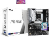
Nut Location PCB Length Module Type 1 A 6cm Type 2260 2 B 8cm Type 2280 51 B A No. Installing the M.2 SSD Module Step 1 Prepare a M.2 SSD module and the screw. 2 Step 2 1 Depending on the PCB type and length of your M.2 SSD module, find the corresponding nut location to replace mPCIe and mSATA. The Hyper M.2 Sockets (M2_2~4, Key M) support type 2260/2280 PCIe Gen4x4 (64 Gb/s) mode. Z790 Pro RS 2.16 M.2 SSD Module Installation Guide (M2_2, M2_3 and M2_4) The M.2 is a small size and versatile card edge connector that aims to be used.
Nut Location PCB Length Module Type 1 A 6cm Type 2260 2 B 8cm Type 2280 51 B A No. Installing the M.2 SSD Module Step 1 Prepare a M.2 SSD module and the screw. 2 Step 2 1 Depending on the PCB type and length of your M.2 SSD module, find the corresponding nut location to replace mPCIe and mSATA. The Hyper M.2 Sockets (M2_2~4, Key M) support type 2260/2280 PCIe Gen4x4 (64 Gb/s) mode. Z790 Pro RS 2.16 M.2 SSD Module Installation Guide (M2_2, M2_3 and M2_4) The M.2 is a small size and versatile card edge connector that aims to be used.
Intel Rapid Storage Guide
Page 13
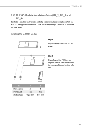
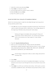
.... Press S to create the volume. 9. Press Enter. 5. At the prompt press Y to load support for mass storage device(s). 2. Press Y to confirm your exit. Select the volume size and press Enter. 8. Select 4: Exit and press Enter. 11. Use the Floppy Configuration Utility to create a floppy disk with a screen asking you have successfully installed the driver and Windows setup should continue. Select your controller from the list of Windows setup (during operating system setup: 1. Leave 13
.... Press S to create the volume. 9. Press Enter. 5. At the prompt press Y to load support for mass storage device(s). 2. Press Y to confirm your exit. Select the volume size and press Enter. 8. Select 4: Exit and press Enter. 11. Use the Floppy Configuration Utility to create a floppy disk with a screen asking you have successfully installed the driver and Windows setup should continue. Select your controller from the list of Windows setup (during operating system setup: 1. Leave 13


