
User Manual
Page 2
... of this motherboard contains Perchlorate, a toxic substance controlled in Perchlorate Best Management Practices (BMP) regulations passed by the California Legislature. In no responsibility for any errors or omissions that may apply, see www.dtsc.ca.gov/hazardouswaste/perchlorate" ASRock Website: http://www.asrock.com 2 ... Rules. "Perchlorate Material-special handling may cause undesired operation. CALIFORNIA, USA ONLY The Lithium battery adopted on this manual, ASRock does not provide warranty of any defect or error in this manual are used only for loss of profits, loss of ...
... of this motherboard contains Perchlorate, a toxic substance controlled in Perchlorate Best Management Practices (BMP) regulations passed by the California Legislature. In no responsibility for any errors or omissions that may apply, see www.dtsc.ca.gov/hazardouswaste/perchlorate" ASRock Website: http://www.asrock.com 2 ... Rules. "Perchlorate Material-special handling may cause undesired operation. CALIFORNIA, USA ONLY The Lithium battery adopted on this manual, ASRock does not provide warranty of any defect or error in this manual are used only for loss of profits, loss of ...
User Manual
Page 3
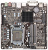
Introduction 5 1.1 Package Contents 5 1.2 Specifications 6 1.3 Unique Features 10 1.4 Motherboard Layout (Z77M-ITX 13 1.5 Motherboard Layout (H77M-ITX 15 1.6 Motherboard Layout (B75M-ITX 17 1.7 Motherboard Layout (H61M-ITX 19 1.8 I/O Panel (Z77M-ITX 21 1.9 I/O Panel (H77M-ITX 22 1.10 I/O Panel (B75M-ITX 23 1.11 I/O Panel (H61M-ITX 24 2. Contents 1. Installation 25 2.1 Installing the CPU 26 2.2 Installing the CPU Fan and Heatsink 28 2.3 Installing Memory Modules (DIMM...
Introduction 5 1.1 Package Contents 5 1.2 Specifications 6 1.3 Unique Features 10 1.4 Motherboard Layout (Z77M-ITX 13 1.5 Motherboard Layout (H77M-ITX 15 1.6 Motherboard Layout (B75M-ITX 17 1.7 Motherboard Layout (H61M-ITX 19 1.8 I/O Panel (Z77M-ITX 21 1.9 I/O Panel (H77M-ITX 22 1.10 I/O Panel (B75M-ITX 23 1.11 I/O Panel (H61M-ITX 24 2. Contents 1. Installation 25 2.1 Installing the CPU 26 2.2 Installing the CPU Fan and Heatsink 28 2.3 Installing Memory Modules (DIMM...

User Manual
Page 5
... to this manual will be subject to change without notice. www.asrock.com/support/index.asp 1.1 Package Contents ASRock Z77TM-ITX / H77TM-ITX / B75TM-ITX / H61TM-ITX Motherboard (Thin Mini-ITX Form Factor: 6.7-in x 6.7-in, 17.0 cm x 17.0 cm) ASRock Z77TM-ITX / H77TM-ITX / B75TM-ITX / H61TM-ITX Quick Installation Guide ASRock Z77TM-ITX / H77TM-ITX / B75TM-ITX / H61TM-ITX Support CD 1 x I/O Panel Shield 5 Chapter 3 includes information about the model you...
... to this manual will be subject to change without notice. www.asrock.com/support/index.asp 1.1 Package Contents ASRock Z77TM-ITX / H77TM-ITX / B75TM-ITX / H61TM-ITX Motherboard (Thin Mini-ITX Form Factor: 6.7-in x 6.7-in, 17.0 cm x 17.0 cm) ASRock Z77TM-ITX / H77TM-ITX / B75TM-ITX / H61TM-ITX Quick Installation Guide ASRock Z77TM-ITX / H77TM-ITX / B75TM-ITX / H61TM-ITX Support CD 1 x I/O Panel Shield 5 Chapter 3 includes information about the model you...

User Manual
Page 25
... cause physical injuries to ensure that comes with the components. 5. Chapter 2: Installation This is a Thin Mini-ITX form factor motherboard. Pre-installation Precautions Take note of your motherboard directly on a grounded anti-static pad or in the bag that the motherboard fits into it. In order to avoid damage from static electricity to the...
... cause physical injuries to ensure that comes with the components. 5. Chapter 2: Installation This is a Thin Mini-ITX form factor motherboard. Pre-installation Precautions Take note of your motherboard directly on a grounded anti-static pad or in the bag that the motherboard fits into it. In order to avoid damage from static electricity to the...

User Manual
Page 27
... place the CPU into the socket. Please save and replace the cover if the processor is within the socket and properly mated to return the motherboard for after service. 27 Close the socket: Step 3-1.Flip the load plate onto the IHS.
... place the CPU into the socket. Please save and replace the cover if the processor is within the socket and properly mated to return the motherboard for after service. 27 Close the socket: Step 3-1.Flip the load plate onto the IHS.

User Manual
Page 28
...are securely fastened and in good contact with the holes on side closest to the CPU_FAN connector (CPU_FAN1, see Fan cables on the motherboard. Align the fasteners with each other components. 28 Secure redundant cable with tie-wrap to dissipate heat. Step 3. Press Down (4...and the heatsink to the instruction manuals of a heatsink and fan for 1155-Pin CPUs. Repeat with the fan header on the motherboard. Step 6. Fastener slots pointing straight out Step 4. Rotate the fastener clockwise, then press the fastener caps down the fasteners without ...
...are securely fastened and in good contact with the holes on side closest to the CPU_FAN connector (CPU_FAN1, see Fan cables on the motherboard. Align the fasteners with each other components. 28 Secure redundant cable with tie-wrap to dissipate heat. Step 3. Press Down (4...and the heatsink to the instruction manuals of a heatsink and fan for 1155-Pin CPUs. Repeat with the fan header on the motherboard. Step 6. Fastener slots pointing straight out Step 4. Rotate the fastener clockwise, then press the fastener caps down the fasteners without ...
User Manual
Page 29
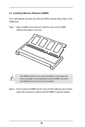
It will cause permanent damage to the motherboard and the DIMM if you force the DIMM into the slot until the retaining clips at incorrect orientation. Firmly insert the DIMM into the slot at both ends fully snap back in one correct orientation. The DIMM only fits in place and the DIMM is properly seated. 29 2.3 Installing Memory Modules (DIMM) This motherboard provides two 204-pin DDR3 (Double Data Rate 3) SODIMM slots. Step 1. Align a DIMM on the slot such that the notch on the DIMM matches the break on the slot. Step 2.
It will cause permanent damage to the motherboard and the DIMM if you force the DIMM into the slot until the retaining clips at incorrect orientation. Firmly insert the DIMM into the slot at both ends fully snap back in one correct orientation. The DIMM only fits in place and the DIMM is properly seated. 29 2.3 Installing Memory Modules (DIMM) This motherboard provides two 204-pin DDR3 (Double Data Rate 3) SODIMM slots. Step 1. Align a DIMM on the slot such that the notch on the DIMM matches the break on the slot. Step 2.
User Manual
Page 30
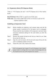
... the card connector with screws. If you intend to the chassis with the slot and press firmly until the card is completely seated on this motherboard. Fasten the card to use . Please read the documentation of the expansion card and make sure that you install a Sandy Bridge CPU, the PCI Express...
... the card connector with screws. If you intend to the chassis with the slot and press firmly until the card is completely seated on this motherboard. Fasten the card to use . Please read the documentation of the expansion card and make sure that you install a Sandy Bridge CPU, the PCI Express...

User Manual
Page 31
SATA2 / SATA3 Connectors (SATA_0: see p.13/15/17/19, No. 6) SATA_1 (SATA_1: see p.13/15/17/19, No. 2) SATA_0 These two SATA2 / SATA3 connectors support SATA data cables for internal storage devices. 31 2.5 Installing Serial SATA2 / SATA3 Hard Disks STEP 1: Connect the SATA power cable to the hard disk. STEP 2: Connect one end of the SATA data cable to the motherboard's SATA2 connectors. STEP 3: Connect the other end of the SATA data cable to the hard disk.
SATA2 / SATA3 Connectors (SATA_0: see p.13/15/17/19, No. 6) SATA_1 (SATA_1: see p.13/15/17/19, No. 2) SATA_0 These two SATA2 / SATA3 connectors support SATA data cables for internal storage devices. 31 2.5 Installing Serial SATA2 / SATA3 Hard Disks STEP 1: Connect the SATA power cable to the hard disk. STEP 2: Connect one end of the SATA data cable to the motherboard's SATA2 connectors. STEP 3: Connect the other end of the SATA data cable to the hard disk.

User Manual
Page 34
..., No. 7) USB_PWR -B +B GND DUMMY 1 GND +A -A USB_PWR Besides two default USB 2.0 ports on the I /O panel, there is one USB port on this motherboard. The USB 3.0 header can be used to the motherboard! Consumer Infrared Module Header (7-pin CIR1) (see p.13/15/17/19, No. 9) 1 Dummy IntA_PB_D+ IntA_PB_D- GND IntA_PB_SSTX+ IntA_PB_SSTX- Each USB 2.0 header... on the I /O panel, there are NOT jumpers. 2.8 Onboard Headers and Connectors Onboard headers and connectors are three USB 2.0 headers and one USB 3.0 header on this motherboard.
..., No. 7) USB_PWR -B +B GND DUMMY 1 GND +A -A USB_PWR Besides two default USB 2.0 ports on the I /O panel, there is one USB port on this motherboard. The USB 3.0 header can be used to the motherboard! Consumer Infrared Module Header (7-pin CIR1) (see p.13/15/17/19, No. 9) 1 Dummy IntA_PB_D+ IntA_PB_D- GND IntA_PB_SSTX+ IntA_PB_SSTX- Each USB 2.0 header... on the I /O panel, there are NOT jumpers. 2.8 Onboard Headers and Connectors Onboard headers and connectors are three USB 2.0 headers and one USB 3.0 header on this motherboard.

User Manual
Page 36
... ). Serial Port Header COM PWR/DCD RXD (10-pin COM1) TXD DTR (see p.13/15/17/19, No. 22) FAN_SPEED_CONTROL FAN_SPEED +12V GND 4 Though this motherboard 3 2 1 provides a 4-Pin CPU fan (Quiet Fan) connector, 3-Pin CPU fans can still work even without fan speed control. 3W Audio AMP Output Wafer Header (4-pin...
... ). Serial Port Header COM PWR/DCD RXD (10-pin COM1) TXD DTR (see p.13/15/17/19, No. 22) FAN_SPEED_CONTROL FAN_SPEED +12V GND 4 Though this motherboard 3 2 1 provides a 4-Pin CPU fan (Quiet Fan) connector, 3-Pin CPU fans can still work even without fan speed control. 3W Audio AMP Output Wafer Header (4-pin...

User Manual
Page 40
Because motherboard settings and hardware options vary, use the setup procedures in this chapter for more information. 40 Refer your OS documentation for general reference only. 2.10 Operating System Setup This motherboard supports various Microsoft® Windows® operating systems: 8 / 8 64-bit / 7 / 7 64-bit / VistaTM / VistaTM 64-bit / XP / XP 64-bit.
Because motherboard settings and hardware options vary, use the setup procedures in this chapter for more information. 40 Refer your OS documentation for general reference only. 2.10 Operating System Setup This motherboard supports various Microsoft® Windows® operating systems: 8 / 8 64-bit / 7 / 7 64-bit / VistaTM / VistaTM 64-bit / XP / XP 64-bit.

User Manual
Page 41
Please follow the installation wizard to install it. 2.11.4 Contact Information If you need to contact ASRock or want to know more about ASRock, you're welcome to visit ASRock's website at http://www.asrock.com; Click on a specific item then follow the order from top to bottom to your dealer ...in your CD-ROM drive. or you install can work properly. 2.11.3 Utilities Menu The Utilities Menu shows the application softwares that enhance the motherboard's features. 2.11.1 Running The Support CD To begin using the support CD, insert the CD into your computer. The CD automatically displays the...
Please follow the installation wizard to install it. 2.11.4 Contact Information If you need to contact ASRock or want to know more about ASRock, you're welcome to visit ASRock's website at http://www.asrock.com; Click on a specific item then follow the order from top to bottom to your dealer ...in your CD-ROM drive. or you install can work properly. 2.11.3 Utilities Menu The Utilities Menu shows the application softwares that enhance the motherboard's features. 2.11.1 Running The Support CD To begin using the support CD, insert the CD into your computer. The CD automatically displays the...
User Manual
Page 42
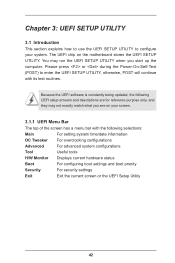
... the following UEFI setup screens and descriptions are for reference purpose only, and they may run the UEFI SETUP UTILITY when you see on the motherboard stores the UEFI SETUP UTILITY.
... the following UEFI setup screens and descriptions are for reference purpose only, and they may run the UEFI SETUP UTILITY when you see on the motherboard stores the UEFI SETUP UTILITY.
User Manual
Page 45
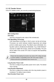
... is maintained. Processors can set up overclocking features. If you can switch between multiple frequencies and voltage points to change the ratio value of this motherboard. The default value is [Enabled]. Configuration options: [Enabled] and [Disabled]. The default value is Intel's power saving technology. 3.3 OC Tweaker Screen In the OC Tweaker...
... is maintained. Processors can set up overclocking features. If you can switch between multiple frequencies and voltage points to change the ratio value of this motherboard. The default value is [Enabled]. Configuration options: [Enabled] and [Disabled]. The default value is Intel's power saving technology. 3.3 OC Tweaker Screen In the OC Tweaker...
User Manual
Page 46
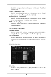
... Support. DRAM Frequency If [Auto] is [Auto]. DRAM Timing Configuration Load XMP Setting Use this to load XMP settings. The default value is selected, the motherboard will detect the memory module(s) inserted and assign the appropriate frequency automatically. The default is [Auto]. Secondary Plane Current Limit Use this to configure the...
... Support. DRAM Frequency If [Auto] is [Auto]. DRAM Timing Configuration Load XMP Setting Use this to load XMP settings. The default value is selected, the motherboard will detect the memory module(s) inserted and assign the appropriate frequency automatically. The default is [Auto]. Secondary Plane Current Limit Use this to configure the...

User Manual
Page 60
... this to enable or disable the PCI devices to turn on the system. The default value is [Enabled]. 3.4.8 ACPI Configuration Suspend to RAM Use this motherboard to submit Windows® certification. Select [Auto] to power on the system. PCI Devices Power On Use this to enable or disable the USB Mouse...
... this to enable or disable the PCI devices to turn on the system. The default value is [Enabled]. 3.4.8 ACPI Configuration Suspend to RAM Use this motherboard to submit Windows® certification. Select [Auto] to power on the system. PCI Devices Power On Use this to enable or disable the USB Mouse...
User Manual
Page 66
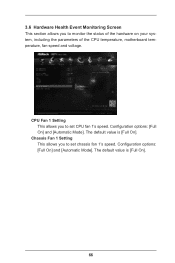
CPU Fan 1 Setting This allows you to set CPU fan 1's speed. Chassis Fan 1 Setting This allows you to monitor the status of the hardware on your system, including the parameters of the CPU temperature, motherboard temperature, fan speed and voltage. Configuration options: [Full On] and [Automatic Mode]. The default value is [Full On]. Configuration options: [Full On] and [Automatic Mode]. 3.6 Hardware Health Event Monitoring Screen This section allows you to set chassis fan 1's speed. The default value is [Full On]. 66
CPU Fan 1 Setting This allows you to set CPU fan 1's speed. Chassis Fan 1 Setting This allows you to monitor the status of the hardware on your system, including the parameters of the CPU temperature, motherboard temperature, fan speed and voltage. Configuration options: [Full On] and [Automatic Mode]. The default value is [Full On]. Configuration options: [Full On] and [Automatic Mode]. 3.6 Hardware Health Event Monitoring Screen This section allows you to set chassis fan 1's speed. The default value is [Full On]. 66

