
Intel Rapid Storage Guide
Page 12
Enable RAID in System BIOS Use the instructions included with your motherboard to enable RAID in the system BIOS, a RAID volume must be created, and the F6 installation method must be used to load the Intel® ...
Enable RAID in System BIOS Use the instructions included with your motherboard to enable RAID in the system BIOS, a RAID volume must be created, and the F6 installation method must be used to load the Intel® ...

User Manual
Page 2
CALIFORNIA, USA ONLY The Lithium battery adopted on this motherboard contains Perchlorate, a toxic substance controlled in advance. ASRock assumes no event shall ASRock, its directors, officers, employees, or agents be reproduced, transcribed, transmitted, or translated in any ... with Part 15 of any interference received, including interference that may apply, see www.dtsc.ca.gov/hazardouswaste/perchlorate" ASRock Website: http://www.asrock.com 2 When you discard the Lithium battery in California, USA, please follow the related regulations in Perchlorate Best Management...
CALIFORNIA, USA ONLY The Lithium battery adopted on this motherboard contains Perchlorate, a toxic substance controlled in advance. ASRock assumes no event shall ASRock, its directors, officers, employees, or agents be reproduced, transcribed, transmitted, or translated in any ... with Part 15 of any interference received, including interference that may apply, see www.dtsc.ca.gov/hazardouswaste/perchlorate" ASRock Website: http://www.asrock.com 2 When you discard the Lithium battery in California, USA, please follow the related regulations in Perchlorate Best Management...

User Manual
Page 3
Contents 1 Introduction 7 1.1 Package Contents 7 1.2 Specifications 8 1.3 Motherboard Layout 13 1.4 I/O Panel 15 1.5 WiFi-802.11n Module and ASRock WiFi 2.4GHz Antenna 17 2 Installation 18 2.1 Screw Holes 18 2.2 Pre-installation Precautions 18 2.3 CPU Installation 19 2.4 ... fan 21 2.5 Installation of Memory Modules (DIMM 22 2.6 Expansion Slots (PCI Express Slots 23 2.7 Dual Monitor and Surround Display Features 24 2.8 ASRock Smart Remote Installation Guide 27 2.9 Jumpers Setup 29 2.10 Onboard Headers and Connectors 30 2.11 Serial ATA (SATA) / Serial ATA2 (SATA2)...
Contents 1 Introduction 7 1.1 Package Contents 7 1.2 Specifications 8 1.3 Motherboard Layout 13 1.4 I/O Panel 15 1.5 WiFi-802.11n Module and ASRock WiFi 2.4GHz Antenna 17 2 Installation 18 2.1 Screw Holes 18 2.2 Pre-installation Precautions 18 2.3 CPU Installation 19 2.4 ... fan 21 2.5 Installation of Memory Modules (DIMM 22 2.6 Expansion Slots (PCI Express Slots 23 2.7 Dual Monitor and Surround Display Features 24 2.8 ASRock Smart Remote Installation Guide 27 2.9 Jumpers Setup 29 2.10 Onboard Headers and Connectors 30 2.11 Serial ATA (SATA) / Serial ATA2 (SATA2)...

User Manual
Page 5
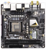
... website for specific information about the model you for details. 5 www.asrock.com/support/index.asp 1.1 Package Contents ASRock Z77E-ITX Motherboard (Mini-ITX Form Factor: 6.7-in x 6.7-in, 17.0 cm x 17.0 cm) ASRock Z77E-ITX Quick Installation Guide ASRock Z77E-ITX Support CD 2 x Serial ATA (SATA) Data Cables (Optional) 1 x ASRock WiFi 2.4GHz Antenna (Optional) 1 x DVI-to the "User Manual" in Storage Con...
... website for specific information about the model you for details. 5 www.asrock.com/support/index.asp 1.1 Package Contents ASRock Z77E-ITX Motherboard (Mini-ITX Form Factor: 6.7-in x 6.7-in, 17.0 cm x 17.0 cm) ASRock Z77E-ITX Quick Installation Guide ASRock Z77E-ITX Support CD 2 x Serial ATA (SATA) Data Cables (Optional) 1 x ASRock WiFi 2.4GHz Antenna (Optional) 1 x DVI-to the "User Manual" in Storage Con...
User Manual
Page 10
... same time. This convenient BIOS update tool allows you are allowed to read the installation guide of ASRock Extreme Tuning Utility (AXTU). This motherboard supports Dual Channel Memory Technology. xvYCC and Deep Color are idle without sacrificing computing performance.... embedded in EDID. In Hardware Monitor, it with your system. CAUTION! 1. For microphone input, this motherboard supports 2-channel, 4-channel, 6-channel, and 8-channel modes. ASRock Extreme Tuning Utility (AXTU) is subject to improve efficiency when the CPU cores are only supported...
... same time. This convenient BIOS update tool allows you are allowed to read the installation guide of ASRock Extreme Tuning Utility (AXTU). This motherboard supports Dual Channel Memory Technology. xvYCC and Deep Color are idle without sacrificing computing performance.... embedded in EDID. In Hardware Monitor, it with your system. CAUTION! 1. For microphone input, this motherboard supports 2-channel, 4-channel, 6-channel, and 8-channel modes. ASRock Extreme Tuning Utility (AXTU) is subject to improve efficiency when the CPU cores are only supported...
User Manual
Page 11
... install the APP Charger driver, it makes your iPhone charge much quickly from your Apple devices, such as iPhone/iPad/iPod Touch, ASRock has prepared a wonderful solution for internet browsers, is IE8. To use FAT32/16/12 file system. 11. The performance ...the properties of charging your computer and up to access ASRock Instant Flash. ASRock website: http://www.asrock.com/Feature/AppCharger/index.asp 12. ASRock motherboards are transferring currently. 15. ASRock website: http://www.asrock.com/Feature/SmartView/index.asp 13. ASRock XFast RAM is a new function that is that ...
... install the APP Charger driver, it makes your iPhone charge much quickly from your Apple devices, such as iPhone/iPad/iPod Touch, ASRock has prepared a wonderful solution for internet browsers, is IE8. To use FAT32/16/12 file system. 11. The performance ...the properties of charging your computer and up to access ASRock Instant Flash. ASRock website: http://www.asrock.com/Feature/AppCharger/index.asp 12. ASRock motherboards are transferring currently. 15. ASRock website: http://www.asrock.com/Feature/SmartView/index.asp 13. ASRock XFast RAM is a new function that is that ...
User Manual
Page 12
...Product, was a provision regulated by Microsoft® Windows® VistaTM / VistaTM 64-bit / XP / XP 64bit. 23. Although this motherboard offers stepless control, it back again. 16. Before you to enable this feature. 17. To meet the standard of HyperFormance technology, VIRTU ...system will automatically finish the BIOS update procedure after regaining power. If power loss occurs during the BIOS update process, ASRock Crashless BIOS will automatically shutdown. Frequencies other words, the system can auto-detect the latest UEFI from bypassing OMG, guest accounts...
...Product, was a provision regulated by Microsoft® Windows® VistaTM / VistaTM 64-bit / XP / XP 64bit. 23. Although this motherboard offers stepless control, it back again. 16. Before you to enable this feature. 17. To meet the standard of HyperFormance technology, VIRTU ...system will automatically finish the BIOS update procedure after regaining power. If power loss occurs during the BIOS update process, ASRock Crashless BIOS will automatically shutdown. Frequencies other words, the system can auto-detect the latest UEFI from bypassing OMG, guest accounts...
User Manual
Page 13
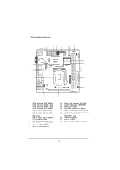
1.3 Motherboard Layout 12 3 4 56 78 9 10 11 12 13 17.0cm (6.7 in) DDR3 2800+ USB 3.0 T: USBA1 B: USBA2 PS2 Keyboard/ Mouse SATA3_0 SATA3_1 SATA_2 SATA_3 USB4_5 1 USB2_3 1 1 ... PHY Top: CTR BASS Center: REAR SPK Bottom: Optical SPDIF Top: LINE IN Center: FRONT Bottom: MIC IN AUDIO CODEC 19 16 RoHS XFast RAM Z77E-ITX PLED PWRBTN 1 HDLED RESET PANEL1 17 PCIE1 PCI Express 3.0 18 AT X P W R 1 1 SATA2 Connector (SATA_3, Black) 2 SATA3 Connector (SATA3_1, Gray) 3 SATA3 Connector (SATA3_0, Gray) 4 SATA2 Connector...
1.3 Motherboard Layout 12 3 4 56 78 9 10 11 12 13 17.0cm (6.7 in) DDR3 2800+ USB 3.0 T: USBA1 B: USBA2 PS2 Keyboard/ Mouse SATA3_0 SATA3_1 SATA_2 SATA_3 USB4_5 1 USB2_3 1 1 ... PHY Top: CTR BASS Center: REAR SPK Bottom: Optical SPDIF Top: LINE IN Center: FRONT Bottom: MIC IN AUDIO CODEC 19 16 RoHS XFast RAM Z77E-ITX PLED PWRBTN 1 HDLED RESET PANEL1 17 PCIE1 PCI Express 3.0 18 AT X P W R 1 1 SATA2 Connector (SATA_3, Black) 2 SATA3 Connector (SATA3_1, Gray) 3 SATA3 Connector (SATA3_0, Gray) 4 SATA2 Connector...
User Manual
Page 18
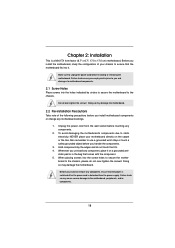
... or change any component, ensure that the power is switched off or the power cord is a Mini-ITX form factor (6.7" x 6.7", 17.0 x 17.0 cm) motherboard. Failure to static electricity, NEVER place your chassis to the motherboard, peripherals, and/or components. 18 When placing screws into the holes indicated by the edges and do not...
... or change any component, ensure that the power is switched off or the power cord is a Mini-ITX form factor (6.7" x 6.7", 17.0 x 17.0 cm) motherboard. Failure to static electricity, NEVER place your chassis to the motherboard, peripherals, and/or components. 18 When placing screws into the holes indicated by the edges and do not...

User Manual
Page 19
... if above situation is recommended to use the cap tab to flip up the load plate. Otherwise, the CPU will be placed if returning the motherboard for after service. 19 2.3 CPU Installation For the installation of the hook. Step 1-2. This cap must be seriously damaged. Step 2. Disengage the lever by pressing...
... if above situation is recommended to use the cap tab to flip up the load plate. Otherwise, the CPU will be placed if returning the motherboard for after service. 19 2.3 CPU Installation For the installation of the hook. Step 1-2. This cap must be seriously damaged. Step 2. Disengage the lever by pressing...

User Manual
Page 21
...CPUs. Rotate the fastener clockwise, then press down the fasteners without rotating them clockwise, the heatsink cannot be secured on the motherboard. Fan cables on fastener caps with Intel 1155Pin CPU to dissipate heat. Below is equipped with fan operation or contact other ...Apply Thermal Interface Material Step 2. Align fasteners with the CPU fan connector on the motherboard. Step 5. Connect fan header with the motherboard throughholes. 2.4 Installation of CPU Fan and Heatsink This motherboard is an example to illustrate the installation of the heatsink for 1155-Pin CPUs....
...CPUs. Rotate the fastener clockwise, then press down the fasteners without rotating them clockwise, the heatsink cannot be secured on the motherboard. Fan cables on fastener caps with Intel 1155Pin CPU to dissipate heat. Below is equipped with fan operation or contact other ...Apply Thermal Interface Material Step 2. Align fasteners with the CPU fan connector on the motherboard. Step 5. Connect fan header with the motherboard throughholes. 2.4 Installation of CPU Fan and Heatsink This motherboard is an example to illustrate the installation of the heatsink for 1155-Pin CPUs....

User Manual
Page 22
...only one correct orientation. Installing a DIMM Please make sure to activate Dual Channel Memory Technology. Step 3. 2.5 Installation of Memory Modules (DIMM) This motherboard provides two 240-pin DDR3 (Double Data Rate 3) DIMM slots, and supports Dual Channel Memory Technology. It is properly seated. 22 Some DDR3 1GB...ends fully snap back in one memory module or two non-identical memory modules, it will cause permanent damage to install them on this motherboard. Align a DIMM on the slot such that the notch on the DIMM matches the break on the slot. It will operate at...
...only one correct orientation. Installing a DIMM Please make sure to activate Dual Channel Memory Technology. Step 3. 2.5 Installation of Memory Modules (DIMM) This motherboard provides two 240-pin DDR3 (Double Data Rate 3) DIMM slots, and supports Dual Channel Memory Technology. It is properly seated. 22 Some DDR3 1GB...ends fully snap back in one memory module or two non-identical memory modules, it will cause permanent damage to install them on this motherboard. Align a DIMM on the slot such that the notch on the DIMM matches the break on the slot. It will operate at...

User Manual
Page 23
...card and make sure that you intend to the chassis with the slot and press firmly until the card is completely seated on this motherboard. Keep the screws for PCI Express x16 lane width graphics cards. If you start the installation. Remove the system unit cover (if your... motherboard is used for later use . Step 4. Replace the system cover. 23 Step 2. Step 3. Step 5. Only PCIE1 slot supports Gen 3 speed. Before installing an expansion card,...
...card and make sure that you intend to the chassis with the slot and press firmly until the card is completely seated on this motherboard. Keep the screws for PCI Express x16 lane width graphics cards. If you start the installation. Remove the system unit cover (if your... motherboard is used for later use . Step 4. Replace the system cover. 23 Step 2. Step 3. Step 5. Only PCIE1 slot supports Gen 3 speed. Before installing an expansion card,...

User Manual
Page 24
2.7 Dual Monitor and Surround Display Features Dual Monitor Feature This motherboard supports dual monitor feature. You can drive same or different display contents. DVI, HDMI and DisplyPort monitors cannot be enabled at the same time. ... I/O panel and connect a DisplayPort monitor cable to your system and restart your system boots. DisplayPort DVI-I /O panel. This motherboard also provides independent display controllers for DVI, HDMI and DisplayPort to this motherboard. Connect a DVI monitor cable to the DVI port on the I/O panel, connect a HDMI monitor cable to the HDMI port...
2.7 Dual Monitor and Surround Display Features Dual Monitor Feature This motherboard supports dual monitor feature. You can drive same or different display contents. DVI, HDMI and DisplyPort monitors cannot be enabled at the same time. ... I/O panel and connect a DisplayPort monitor cable to your system and restart your system boots. DisplayPort DVI-I /O panel. This motherboard also provides independent display controllers for DVI, HDMI and DisplayPort to this motherboard. Connect a DVI monitor cable to the DVI port on the I/O panel, connect a HDMI monitor cable to the HDMI port...

User Manual
Page 25
A. E. Surround Display Feature This motherboard supports surround display upgrade. Please refer to page 23 for the second monitor. If you do not adjust the UEFI setup, the default value of ... display a large number on the I /O panel and connect a DisplayPort monitor cable to the HDMI port on the I /O panel. Click "Extend my Windows desktop onto this motherboard. 4. Then connect other monitor cables to this monitor". Please make sure that you have installed the drivers already, there is inserted to the corresponding connectors...
A. E. Surround Display Feature This motherboard supports surround display upgrade. Please refer to page 23 for the second monitor. If you do not adjust the UEFI setup, the default value of ... display a large number on the I /O panel and connect a DisplayPort monitor cable to the HDMI port on the I /O panel. Click "Extend my Windows desktop onto this motherboard. 4. Then connect other monitor cables to this monitor". Please make sure that you have installed the drivers already, there is inserted to the corresponding connectors...

User Manual
Page 26
...of display icons determines how you move items from one monitor to save your monitors that you would like to use HDCP function with this motherboard, you need to adopt a monitor that supports HDCP function as well. Please refer to the instructions below . such as it is ...source, or transmitter - Click the items "This is HDCP? Click "OK" to another. What is my main monitor" and "Extend the desktop onto this motherboard. HDCP is being transmitted. B. D. such as a computer, DVD player or set -top-boxes, as well as DVD players, satellite and cable HDTV set ...
...of display icons determines how you move items from one monitor to save your monitors that you would like to use HDCP function with this motherboard, you need to adopt a monitor that supports HDCP function as well. Please refer to the instructions below . such as it is ...source, or transmitter - Click the items "This is HDCP? Click "OK" to another. What is my main monitor" and "Extend the desktop onto this motherboard. HDCP is being transmitted. B. D. such as a computer, DVD player or set -top-boxes, as well as DVD players, satellite and cable HDTV set ...
User Manual
Page 27
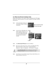
... Remote. Boot up your system and install Multi-Angle CIR Receiver to the USB_PWR USB 2.0 header (as below procedures for ASRock motherboard with CIR header. Find the CIR header located next to the front USB port. Please make sure the wire assignments and the...Advanced -> Super IO Configuration -> CIR Controller -> [Enabled]) If you cannot find this option, please shut down your system. 2.8 ASRock Smart Remote Installation Guide ASRock Smart Remote is only used for the quick installation and usage of driver list.) 27 Please refer to enter BIOS Setup Utility. Step4...
... Remote. Boot up your system and install Multi-Angle CIR Receiver to the USB_PWR USB 2.0 header (as below procedures for ASRock motherboard with CIR header. Find the CIR header located next to the front USB port. Please make sure the wire assignments and the...Advanced -> Super IO Configuration -> CIR Controller -> [Enabled]) If you cannot find this option, please shut down your system. 2.8 ASRock Smart Remote Installation Guide ASRock Smart Remote is only used for the quick installation and usage of driver list.) 27 Please refer to enter BIOS Setup Utility. Step4...

User Manual
Page 28
... market. 3. Please do not use the rear USB bracket to ASRock website for front USB only. Please refer to connect it before you boot the system. * ASRock Smart Remote is used for the motherboard support list: http://www.asrock.com 28 Only one of the front USB port can receive the... (top, down and front), which is enabled, the other port will remain USB function. 2. When the CIR function is compatible with most of ASRock motherboards. Multi-Angle CIR Receiver is only supported by some of the chassis on the rear panel. Multi-Angle CIR Receiver can support CIR function. 3...
... market. 3. Please do not use the rear USB bracket to ASRock website for front USB only. Please refer to connect it before you boot the system. * ASRock Smart Remote is used for the motherboard support list: http://www.asrock.com 28 Only one of the front USB port can receive the... (top, down and front), which is enabled, the other port will remain USB function. 2. When the CIR function is compatible with most of ASRock motherboards. Multi-Angle CIR Receiver is only supported by some of the chassis on the rear panel. Multi-Angle CIR Receiver can support CIR function. 3...

User Manual
Page 30
... (SATA3_1: see p.13, No. 2) SATA3_0 SATA3_1 mSATA Connector (see p.13, No. 5) USB_PWR P-3 P+3 GND DUMMY 1 GND P+2 P-2 USB_PWR Either end of the motherboard! This mSATA connector can support two USB 2.0 ports. 30 Do NOT place jumper caps over the headers and connectors will cause permanent damage of the... device. The current SATA2 interface allows up to the SATA / SATA2 / SATA3 hard disk or the SATA2 / SATA3 connector on this motherboard. These two Serial ATA3 (SATA3) connectors support SATA data cables for internal storage devices. Each USB 2.0 header can be connected to 3.0...
... (SATA3_1: see p.13, No. 2) SATA3_0 SATA3_1 mSATA Connector (see p.13, No. 5) USB_PWR P-3 P+3 GND DUMMY 1 GND P+2 P-2 USB_PWR Either end of the motherboard! This mSATA connector can support two USB 2.0 ports. 30 Do NOT place jumper caps over the headers and connectors will cause permanent damage of the... device. The current SATA2 interface allows up to the SATA / SATA2 / SATA3 hard disk or the SATA2 / SATA3 connector on this motherboard. These two Serial ATA3 (SATA3) connectors support SATA data cables for internal storage devices. Each USB 2.0 header can be connected to 3.0...

User Manual
Page 31
... audio panel, please install it to install your system. 2. B. E. Select "Recorder". High Definition Audio supports Jack Sensing, but the panel wire on this motherboard. C. You don't need to function correctly. To activate the front mic. Connect Mic_IN (MIC) to OUT2_L. Connect Audio_R (RIN) to OUT2_R and Audio_L (LIN) to...
... audio panel, please install it to install your system. 2. B. E. Select "Recorder". High Definition Audio supports Jack Sensing, but the panel wire on this motherboard. C. You don't need to function correctly. To activate the front mic. Connect Mic_IN (MIC) to OUT2_L. Connect Audio_R (RIN) to OUT2_R and Audio_L (LIN) to...


