
User Manual
Page 12
... it is turned off mode condition. While CPU overheat is not supported by Microsoft® Windows® VistaTM / VistaTM 64-bit / XP / XP 64bit. 23. ASRock On/Off Play Technology allows users to enjoy the great audio experience from portable audio devices, such as MP3 players or mobile phones to your... PC, even when the PC is not recommended to adopt three different CPU cooler types, Socket LGA 775, LGA 1155 and LGA 1156. ASRock XFast RAM is detected, the system will automatically shutdown.
... it is turned off mode condition. While CPU overheat is not supported by Microsoft® Windows® VistaTM / VistaTM 64-bit / XP / XP 64bit. 23. ASRock On/Off Play Technology allows users to enjoy the great audio experience from portable audio devices, such as MP3 players or mobile phones to your... PC, even when the PC is not recommended to adopt three different CPU cooler types, Socket LGA 775, LGA 1155 and LGA 1156. ASRock XFast RAM is detected, the system will automatically shutdown.

User Manual
Page 13
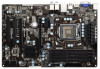
...1 Front USB 3.0 Top: SIDE SPK Center: REAR SPK Bottom: CTR BASS 9 Top: LINE IN Center: FRONT Bottom: MIC IN ErP/EuP Ready 34 PCIE1 Z75 Pro3 LAN PHY PCIE2 PCI Express 3.0 SATA3_1 SATA3_0 10 11 CMOS 33 Battery Super I/O XFast LAN XFast USB XFast RAM 12 Intel... 20 19 18 1 CPU Fan Connector (CPU_FAN1) 19 Power LED Header (PLED1) 2 CPU Fan Connector (CPU_FAN2) 20 System Panel Header (PANEL1, Black) 3 1155-Pin CPU Socket 21 Chassis Fan Connector (CHA_FAN2) 4 ATX 12V Power Connector (ATX12V1) 22 USB 2.0 Header (USB4_5, Black) 5 2 x 240-pin DDR3 DIMM Slots 23 USB 2.0 Header ...
...1 Front USB 3.0 Top: SIDE SPK Center: REAR SPK Bottom: CTR BASS 9 Top: LINE IN Center: FRONT Bottom: MIC IN ErP/EuP Ready 34 PCIE1 Z75 Pro3 LAN PHY PCIE2 PCI Express 3.0 SATA3_1 SATA3_0 10 11 CMOS 33 Battery Super I/O XFast LAN XFast USB XFast RAM 12 Intel... 20 19 18 1 CPU Fan Connector (CPU_FAN1) 19 Power LED Header (PLED1) 2 CPU Fan Connector (CPU_FAN2) 20 System Panel Header (PANEL1, Black) 3 1155-Pin CPU Socket 21 Chassis Fan Connector (CHA_FAN2) 4 ATX 12V Power Connector (ATX12V1) 22 USB 2.0 Header (USB4_5, Black) 5 2 x 240-pin DDR3 DIMM Slots 23 USB 2.0 Header ...

User Manual
Page 16
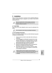
... so may damage the motherboard. 2.2 Pre-installation Precautions Take note of your motherboard directly on a grounded anti- Chapter 2: Installation This is detached from the wall socket before touching any components. 2. To avoid damaging the motherboard's components due to static electricity, NEVER place your chassis to do not over -tighten the screws...
... so may damage the motherboard. 2.2 Pre-installation Precautions Take note of your motherboard directly on a grounded anti- Chapter 2: Installation This is detached from the wall socket before touching any components. 2. To avoid damaging the motherboard's components due to static electricity, NEVER place your chassis to do not over -tighten the screws...

User Manual
Page 17
... recommended to use the cap tab to flip up the load plate. Load Plate Load Lever Contact Array Socket Body 1155-Pin Socket Overview Before you insert the 1155-Pin CPU into the socket if above situation is unclean or if there are any bent pins in order to handle and avoid kicking... the PnP Cap (Pick and Place Cap). 1. Keep the lever positioned at about 135 degrees in the socket. Otherwise, the CPU will be placed if returning the motherboard for after service. 17 Open the socket: Step 1-1. Step 1. Step 2. Disengage the lever by pressing it down and sliding it out of Intel 1155...
... recommended to use the cap tab to flip up the load plate. Load Plate Load Lever Contact Array Socket Body 1155-Pin Socket Overview Before you insert the 1155-Pin CPU into the socket if above situation is unclean or if there are any bent pins in order to handle and avoid kicking... the PnP Cap (Pick and Place Cap). 1. Keep the lever positioned at about 135 degrees in the socket. Otherwise, the CPU will be placed if returning the motherboard for after service. 17 Open the socket: Step 1-1. Step 1. Step 2. Disengage the lever by pressing it down and sliding it out of Intel 1155...

User Manual
Page 18
... key Pin1 Pin1 orientation key notch 1155-Pin CPU alignment key 1155-Pin Socket For proper inserting, please ensure to the orient keys. Carefully place the CPU into the socket by the edge which is within the socket and properly mated to match the two orientation key notches of the... socket. Close the socket: Step 4-1. Flip the load plate onto the IHS. Locate Pin1 and the two...
... key Pin1 Pin1 orientation key notch 1155-Pin CPU alignment key 1155-Pin Socket For proper inserting, please ensure to the orient keys. Carefully place the CPU into the socket by the edge which is within the socket and properly mated to match the two orientation key notches of the... socket. Close the socket: Step 4-1. Flip the load plate onto the IHS. Locate Pin1 and the two...

User Manual
Page 19
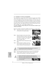
...components. Step 4. Step 5. The white throughholes are securely fastened and in good contact with thumb to adopt three different CPU cooler types, Socket LGA 775, LGA 1155 and LGA 1156. Ensure that this motherboard supports Combo Cooler Option (C.C.O.), which provides flexible options to install ... are for 1155-Pin CPUs. Step 6. Then connect the CPU fan to improve heat dissipation. Step 1. Place the heatsink onto the socket. Fan cables on side closest to MB header Fastener slots pointing straight out Press Down (4 Places) If you need to spray thermal...
...components. Step 4. Step 5. The white throughholes are securely fastened and in good contact with thumb to adopt three different CPU cooler types, Socket LGA 775, LGA 1155 and LGA 1156. Ensure that this motherboard supports Combo Cooler Option (C.C.O.), which provides flexible options to install ... are for 1155-Pin CPUs. Step 6. Then connect the CPU fan to improve heat dissipation. Step 1. Place the heatsink onto the socket. Fan cables on side closest to MB header Fastener slots pointing straight out Press Down (4 Places) If you need to spray thermal...

Quick Installation Guide
Page 2
...BASS 9 Top: LINE IN Center: FRONT Bottom: MIC IN ErP/EuP Ready 34 PCIE1 Z75 Pro3 LAN PHY PCIE2 PCI Express 3.0 SATA3_1 SATA3_0 10 11 CMOS 33 Battery Super I/O XFast LAN XFast USB XFast RAM ... (CPU_FAN1) 19 Power LED Header (PLED1) 2 CPU Fan Connector (CPU_FAN2) 20 System Panel Header (PANEL1, Black) 3 1155-Pin CPU Socket 21 Chassis Fan Connector (CHA_FAN2) 4 ATX 12V Power Connector (ATX12V1) 22 USB 2.0 Header (USB4_5, Black) 5 2 x 240-pin ...(PCIE1, Black) 18 Chassis Speaker Header (SPEAKER1, Black) 35 Power Fan Connector (PWR_FAN1) 2 ASRock Z75 Pro3 Motherboard English
...BASS 9 Top: LINE IN Center: FRONT Bottom: MIC IN ErP/EuP Ready 34 PCIE1 Z75 Pro3 LAN PHY PCIE2 PCI Express 3.0 SATA3_1 SATA3_0 10 11 CMOS 33 Battery Super I/O XFast LAN XFast USB XFast RAM ... (CPU_FAN1) 19 Power LED Header (PLED1) 2 CPU Fan Connector (CPU_FAN2) 20 System Panel Header (PANEL1, Black) 3 1155-Pin CPU Socket 21 Chassis Fan Connector (CHA_FAN2) 4 ATX 12V Power Connector (ATX12V1) 22 USB 2.0 Header (USB4_5, Black) 5 2 x 240-pin ...(PCIE1, Black) 18 Chassis Speaker Header (SPEAKER1, Black) 35 Power Fan Connector (PWR_FAN1) 2 ASRock Z75 Pro3 Motherboard English

Quick Installation Guide
Page 12
...other than 50% under 1.00W in ACPI S5 mode)! Before you install the PC system. 21. ASRock XFast RAM is turned off (or in off mode condition. EuP stands for Energy Using Product, was ...and Intel® USB 3.0 ports are required. According to define the power consumption for more details. 12 ASRock Z75 Pro3 Motherboard English 18. ASRock On/Off Play Technology allows users to enjoy the great audio experience from portable audio devices, such as MP3...most convenient computing environment. 19. According to adopt three different CPU cooler types, Socket LGA 775, LGA 1155 and LGA 1156.
...other than 50% under 1.00W in ACPI S5 mode)! Before you install the PC system. 21. ASRock XFast RAM is turned off (or in off mode condition. EuP stands for Energy Using Product, was ...and Intel® USB 3.0 ports are required. According to define the power consumption for more details. 12 ASRock Z75 Pro3 Motherboard English 18. ASRock On/Off Play Technology allows users to enjoy the great audio experience from portable audio devices, such as MP3...most convenient computing environment. 19. According to adopt three different CPU cooler types, Socket LGA 775, LGA 1155 and LGA 1156.
Quick Installation Guide
Page 13
... static electricity, NEVER place your chassis to the chassis, please do so may damage the motherboard. Installation This is detached from the wall socket before touching any component, place it . To avoid damaging the motherboard's components due to use a grounded wrist strap or touch a safety... pad or in the bag that the motherboard fits into the screw holes to the motherboard, peripherals, and/or components. 13 ASRock Z75 Pro3 Motherboard English Doing so may cause severe damage to secure the mother- Doing so may cause physical injuries to unplug the power cord before...
... static electricity, NEVER place your chassis to the chassis, please do so may damage the motherboard. Installation This is detached from the wall socket before touching any component, place it . To avoid damaging the motherboard's components due to use a grounded wrist strap or touch a safety... pad or in the bag that the motherboard fits into the screw holes to the motherboard, peripherals, and/or components. 13 ASRock Z75 Pro3 Motherboard English Doing so may cause severe damage to secure the mother- Doing so may cause physical injuries to unplug the power cord before...

Quick Installation Guide
Page 14
...cap must be seriously damaged. Step 2. Otherwise, the CPU will be placed if returning the motherboard for after service. 14 ASRock Z75 Pro3 Motherboard It is recommended to use the cap tab to insert the CPU into the socket, please check if the CPU surface is found. Load Plate Load Lever Contact Array... Socket Body 1155-Pin Socket Overview Before you insert the 1155-Pin CPU into the socket if above situation is unclean or if there are any ...
...cap must be seriously damaged. Step 2. Otherwise, the CPU will be placed if returning the motherboard for after service. 14 ASRock Z75 Pro3 Motherboard It is recommended to use the cap tab to insert the CPU into the socket, please check if the CPU surface is found. Load Plate Load Lever Contact Array... Socket Body 1155-Pin Socket Overview Before you insert the 1155-Pin CPU into the socket if above situation is unclean or if there are any ...

Quick Installation Guide
Page 15
... key notch alignment key Pin1 Pin1 orientation key notch 1155-Pin CPU alignment key 1155-Pin Socket For proper inserting, please ensure to the orient keys. Flip the load plate onto the IHS. English 15 ASRock Z75 Pro3 Motherboard Step 3-3. Press down the load lever, and secure it with a black line. Insert the 1155...
... key notch alignment key Pin1 Pin1 orientation key notch 1155-Pin CPU alignment key 1155-Pin Socket For proper inserting, please ensure to the orient keys. Flip the load plate onto the IHS. English 15 ASRock Z75 Pro3 Motherboard Step 3-3. Press down the load lever, and secure it with a black line. Insert the 1155...
Quick Installation Guide
Page 16
.... 2.4 Installation of CPU Fan and Heatsink This motherboard is an example to illustrate the installation of the heatsink for Socket LGA 1155/1156 CPU fan. 16 ASRock Z75 Pro3 Motherboard Below is equipped with fan operation or contact other . Step 1. Step 3. Align fasteners with each other components. Step 5. Step 6. Secure redundant cable with tie...
.... 2.4 Installation of CPU Fan and Heatsink This motherboard is an example to illustrate the installation of the heatsink for Socket LGA 1155/1156 CPU fan. 16 ASRock Z75 Pro3 Motherboard Below is equipped with fan operation or contact other . Step 1. Step 3. Align fasteners with each other components. Step 5. Step 6. Secure redundant cable with tie...