
User Manual
Page 12
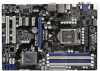
...Z68 Pro3 7 8 32 PCIE1 PCI Express 2.0 CMOS ErP/EuP Ready 31 PCIE2 Battery USB 3.0 30 Super I/O PCIE3 Intel 9 Z68 SATA3 6Gb/s 29 28 27 PCIE4 RoHS AUDIO CODEC 1 HDMI_SPDIF1 HD_AUDIO1 1 COM1 1 PCI1 PCI2 IR1 1 USB6_7 1 1 CIR1 USB8_9 1 CLRCMOS1 1 64Mb BIOS SATA3_0 1 SPEAKER1 SATA3_1 1 PLED1 PLED PWRBTN 1 HDLED RESET... Fan Connector (CHA_FAN2) 26 Front Panel Audio Header 8 Chassis Fan Connector (CHA_FAN3) (HD_AUDIO1, White) 9 Intel Z68 Chipset 27 HDMI_SPDIF Header 10 SATA3 Connector (SATA3_0, White) (HDMI_SPDIF1, White) 11 SATA2 Connector (SATA2_2, Blue) 28...
...Z68 Pro3 7 8 32 PCIE1 PCI Express 2.0 CMOS ErP/EuP Ready 31 PCIE2 Battery USB 3.0 30 Super I/O PCIE3 Intel 9 Z68 SATA3 6Gb/s 29 28 27 PCIE4 RoHS AUDIO CODEC 1 HDMI_SPDIF1 HD_AUDIO1 1 COM1 1 PCI1 PCI2 IR1 1 USB6_7 1 1 CIR1 USB8_9 1 CLRCMOS1 1 64Mb BIOS SATA3_0 1 SPEAKER1 SATA3_1 1 PLED1 PLED PWRBTN 1 HDLED RESET... Fan Connector (CHA_FAN2) 26 Front Panel Audio Header 8 Chassis Fan Connector (CHA_FAN3) (HD_AUDIO1, White) 9 Intel Z68 Chipset 27 HDMI_SPDIF Header 10 SATA3 Connector (SATA3_0, White) (HDMI_SPDIF1, White) 11 SATA2 Connector (SATA2_2, Blue) 28...

User Manual
Page 26
... Default Clear CMOS Description Note: CLRCMOS1 allows you do not clear the CMOS right after you update the BIOS. If you need to clear the CMOS when you just finish updating the BIOS, you must boot up the system first, and then shut it down before you to clear the... jumpers are "Short" when jumper cap is placed on these 2 pins. The illustration shows a 3-pin jumper whose pin1 and pin2 are setup. To clear and reset the system parameters to short pin2 and pin3 on pins, the jumper is placed on CLRCMOS1 for 5 seconds. After waiting for 15 seconds, use a jumper...
... Default Clear CMOS Description Note: CLRCMOS1 allows you do not clear the CMOS right after you update the BIOS. If you need to clear the CMOS when you just finish updating the BIOS, you must boot up the system first, and then shut it down before you to clear the... jumpers are "Short" when jumper cap is placed on these 2 pins. The illustration shows a 3-pin jumper whose pin1 and pin2 are setup. To clear and reset the system parameters to short pin2 and pin3 on pins, the jumper is placed on CLRCMOS1 for 5 seconds. After waiting for 15 seconds, use a jumper...

Quick Installation Guide
Page 2
... 33 LAN PHY Z68 Pro3 7 8 32 PCIE1 PCI Express 2.0 CMOS ErP/EuP Ready 31 PCIE2 Battery USB 3.0 30 Super I/O PCIE3 Intel 9 Z68 SATA3 6Gb/s 29 28 27 PCIE4 RoHS AUDIO CODEC 1 HDMI_SPDIF1 HD_AUDIO1 1 COM1 1 PCI1 PCI2 IR1 1 USB6_7 1 1 CIR1 USB8_9 1 CLRCMOS1 1 64Mb BIOS SATA3_0 1 SPEAKER1 SATA3_1 1 PLED1 PLED PWRBTN 1 HDLED RESET PANEL1 SATA2_2 SATA2_3... Fan Connector (CPU_FAN2) 17 SATA3 Connector (SATA3_1, White) 34 Chassis Fan Connector (CHA_FAN1) 18 Chassis Speaker Header (SPEAKER 1, White) 35 CPU Fan Connector (CPU_FAN1) 2 ASRock Z68 Pro3 Motherboard English
... 33 LAN PHY Z68 Pro3 7 8 32 PCIE1 PCI Express 2.0 CMOS ErP/EuP Ready 31 PCIE2 Battery USB 3.0 30 Super I/O PCIE3 Intel 9 Z68 SATA3 6Gb/s 29 28 27 PCIE4 RoHS AUDIO CODEC 1 HDMI_SPDIF1 HD_AUDIO1 1 COM1 1 PCI1 PCI2 IR1 1 USB6_7 1 1 CIR1 USB8_9 1 CLRCMOS1 1 64Mb BIOS SATA3_0 1 SPEAKER1 SATA3_1 1 PLED1 PLED PWRBTN 1 HDLED RESET PANEL1 SATA2_2 SATA2_3... Fan Connector (CPU_FAN2) 17 SATA3 Connector (SATA3_1, White) 34 Chassis Fan Connector (CHA_FAN1) 18 Chassis Speaker Header (SPEAKER 1, White) 35 CPU Fan Connector (CPU_FAN1) 2 ASRock Z68 Pro3 Motherboard English

Quick Installation Guide
Page 23
...cap is placed on pins, the jumper is placed on pins, the jumper is removed. To clear and reset the system parameters to clear the CMOS when you just finish updating the BIOS, you must boot up the system first, and then shut it down before you do not ... battery is "Open". If no jumper cap is placed on these 2 pins. English 23 ASRock Z68 Pro3 Motherboard Jumper Clear CMOS Jumper (CLRCMOS1) (see p.2, No. 20) Setting Default Clear CMOS Description Note: CLRCMOS1 allows you update the BIOS. If you need to default setup, please turn off the computer and unplug the power...
...cap is placed on pins, the jumper is placed on pins, the jumper is removed. To clear and reset the system parameters to clear the CMOS when you just finish updating the BIOS, you must boot up the system first, and then shut it down before you do not ... battery is "Open". If no jumper cap is placed on these 2 pins. English 23 ASRock Z68 Pro3 Motherboard Jumper Clear CMOS Jumper (CLRCMOS1) (see p.2, No. 20) Setting Default Clear CMOS Description Note: CLRCMOS1 allows you update the BIOS. If you need to default setup, please turn off the computer and unplug the power...

Quick Installation Guide
Page 31
...VistaTM 64-bit / XP / XP 64-bit. For the detailed information about BIOS Setup, please refer to enter BIOS Setup after POST, please restart the system by pressing + + , or pressing the reset button on the motherboard stores BIOS Setup Utility. If you wish to the User Manual (PDF file)... the CD into your computer. When you to select among the predetermined choices. The BIOS Setup program is a menu-driven program, which allows you start up the computer, please press or during the Power-On-Self-Test (POST) to display the menus. 31 ASRock Z68 Pro3 Motherboard English
...VistaTM 64-bit / XP / XP 64-bit. For the detailed information about BIOS Setup, please refer to enter BIOS Setup after POST, please restart the system by pressing + + , or pressing the reset button on the motherboard stores BIOS Setup Utility. If you wish to the User Manual (PDF file)... the CD into your computer. When you to select among the predetermined choices. The BIOS Setup program is a menu-driven program, which allows you start up the computer, please press or during the Power-On-Self-Test (POST) to display the menus. 31 ASRock Z68 Pro3 Motherboard English


