
Intel Rapid Storage Guide
Page 12
... the Intel Rapid Storage Technology option ROM status screen appears during operating system setup. Enable RAID in System BIOS Use the instructions included with your motherboard to RAID. 5. Switch the SATA Operation Mode option to enable RAID in the system BIOS, a RAID volume must be created, and the F6 installation method...
... the Intel Rapid Storage Technology option ROM status screen appears during operating system setup. Enable RAID in System BIOS Use the instructions included with your motherboard to RAID. 5. Switch the SATA Operation Mode option to enable RAID in the system BIOS, a RAID volume must be created, and the F6 installation method...

Intel Smart Response Installation Guide
Page 1
... drivers, including RST storage driver version 10.5 or later. 2. For the new version RST driver, please check our website for the latest information: http://www.asrock.com * Before you use RST function, you want to use the full SSD as Cache device or only 20GB, and if you just need to... the screen. 4. When pop-up menu appears, chose which SSD you wish to use Enhanced or Maximized Mode. 6. Intel Smart Response Technology Installation Guide This motherboard supports Intel Smart Response Technology.
... drivers, including RST storage driver version 10.5 or later. 2. For the new version RST driver, please check our website for the latest information: http://www.asrock.com * Before you use RST function, you want to use the full SSD as Cache device or only 20GB, and if you just need to... the screen. 4. When pop-up menu appears, chose which SSD you wish to use Enhanced or Maximized Mode. 6. Intel Smart Response Technology Installation Guide This motherboard supports Intel Smart Response Technology.

User Manual
Page 2
...in any form or by any means, except duplication of documentation by the purchaser for backup purpose, without written consent of ASRock Inc. "Perchlorate Material-special handling may cause undesired operation. Copyright Notice: No part of this manual may be reproduced, transcribed,...conditions: (1) this device may not cause harmful interference, and (2) this manual. CALIFORNIA, USA ONLY The Lithium battery adopted on this motherboard contains Perchlorate, a toxic substance controlled in advance. When you discard the Lithium battery in California, USA, please follow the related ...
...in any form or by any means, except duplication of documentation by the purchaser for backup purpose, without written consent of ASRock Inc. "Perchlorate Material-special handling may cause undesired operation. Copyright Notice: No part of this manual may be reproduced, transcribed,...conditions: (1) this device may not cause harmful interference, and (2) this manual. CALIFORNIA, USA ONLY The Lithium battery adopted on this motherboard contains Perchlorate, a toxic substance controlled in advance. When you discard the Lithium battery in California, USA, please follow the related ...
User Manual
Page 3
... Contents 5 1.2 Speci cations 6 1.3 Motherboard Layout 13 1.4 I/O Panel 14 2 Installation 16 2.1 Screw Holes 16 2.2 Pre-installation Precautions 16 2.3 CPU Installation 17 2.4 Installation of Heatsink and CPU fan 19 2.5 Installation of Memory Modules (DIMM 20 2.6 Expansion Slots (PCI and PCI Express Slots 22 2.7 Dual Monitor and Surround Display Features 23 2.8 ASRock Smart Remote Installation...
... Contents 5 1.2 Speci cations 6 1.3 Motherboard Layout 13 1.4 I/O Panel 14 2 Installation 16 2.1 Screw Holes 16 2.2 Pre-installation Precautions 16 2.3 CPU Installation 17 2.4 Installation of Heatsink and CPU fan 19 2.5 Installation of Memory Modules (DIMM 20 2.6 Expansion Slots (PCI and PCI Express Slots 22 2.7 Dual Monitor and Surround Display Features 23 2.8 ASRock Smart Remote Installation...
User Manual
Page 5
... Manual" in our support CD for speci c information about the model you are using. ASRock website http://www.asrock.com If you for purchasing ASRock Z68 Pro3 Gen3 motherboard, a reliable motherboard produced under ASRock's consistently stringent quality control. www.asrock.com/support/index.asp 1.1 Package Contents ASRock Z68 Pro3 Gen3 Motherboard (ATX Form Factor: 12.0-in x 7.5-in Storage Con guration to AHCI mode. It delivers...
... Manual" in our support CD for speci c information about the model you are using. ASRock website http://www.asrock.com If you for purchasing ASRock Z68 Pro3 Gen3 motherboard, a reliable motherboard produced under ASRock's consistently stringent quality control. www.asrock.com/support/index.asp 1.1 Package Contents ASRock Z68 Pro3 Gen3 Motherboard (ATX Form Factor: 12.0-in x 7.5-in Storage Con guration to AHCI mode. It delivers...
User Manual
Page 10
...system performance. In OC DNA, you to read the installation guide of your OC settings as HDMIport. 7. For audio output, this motherboard supports both stereo and mono modes. With this utility, you to the operating system limitation, the actual memory size may depend on ... Deep Color are idle without entering operating systems rst like MS-DOS or Windows®. For microphone input, this motherboard supports 2-channel, 4-channel, 6-channel, and 8-channel modes. ASRock Extreme Tuning Utility (AXTU) is an all-in-one tool to ne-tune different system functions in Flash ROM...
...system performance. In OC DNA, you to read the installation guide of your OC settings as HDMIport. 7. For audio output, this motherboard supports both stereo and mono modes. With this utility, you to the operating system limitation, the actual memory size may depend on ... Deep Color are idle without entering operating systems rst like MS-DOS or Windows®. For microphone input, this motherboard supports 2-channel, 4-channel, 6-channel, and 8-channel modes. ASRock Extreme Tuning Utility (AXTU) is an all-in-one tool to ne-tune different system functions in Flash ROM...

User Manual
Page 11
..., your Facebook friends and your computer and up to 40% faster than ever. This motherboard also provides a free 3.5mm audio cable (optional) that helps you - ASRock APP Charger. ASRock APP Charger allows you are exclusively equipped with friends on the property of charging your browser...charging when your PC, even when the PC is IE8. With APP Charger driver installed, you can lower the latency in game. ASRock motherboards are currently transferring. 15. Please be noted that combines your most convenient computing environment. 11 BIOS setup menu to RAM (S3), ...
..., your Facebook friends and your computer and up to 40% faster than ever. This motherboard also provides a free 3.5mm audio cable (optional) that helps you - ASRock APP Charger. ASRock APP Charger allows you are exclusively equipped with friends on the property of charging your browser...charging when your PC, even when the PC is IE8. With APP Charger driver installed, you can lower the latency in game. ASRock motherboards are currently transferring. 15. Please be noted that combines your most convenient computing environment. 11 BIOS setup menu to RAM (S3), ...
User Manual
Page 12
..., LGA 1155 and LGA 1156. For EuP ready power supply selection, we recommend you resume the system, please check if the CPU fan on the motherboard functions properly and unplug the power cord, then plug it is detected, the system will automatically shutdown. To improve heat dissipation, remember to de ne... and 1156 CPU Fan can be under 100 mA current consumption. To meet the standard of the system or damage the CPU. 18. Although this motherboard offers stepless control, it back again. According to Intel's suggestion, the EuP ready power supply must meet EuP standard, an EuP ready...
..., LGA 1155 and LGA 1156. For EuP ready power supply selection, we recommend you resume the system, please check if the CPU fan on the motherboard functions properly and unplug the power cord, then plug it is detected, the system will automatically shutdown. To improve heat dissipation, remember to de ne... and 1156 CPU Fan can be under 100 mA current consumption. To meet the standard of the system or damage the CPU. 18. Although this motherboard offers stepless control, it back again. According to Intel's suggestion, the EuP ready power supply must meet EuP standard, an EuP ready...
User Manual
Page 13
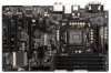
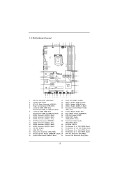
1.3 Motherboard Layout USB 2.0 T: USB0 B: USB1 1 2 19.1cm (7.5 in) 3 4 5 6 CPU_FAN1 ATX12V1 PWR_FAN1...SATA2_3 SATA3_1 XFast LAN 10 33 32 PCIE2 CMOS Battery RoHS SATA2_4 SATA2_2 SATA3_0 31 Super I/O PCIE3 PCI Express 3.0 Z68 Pro3 Gen3 11 12 SATA3 6Gb/s 13 ErP/EuP Ready 30 29 PCIE4 AUDIO CODEC HD_AUDIO1 HDMI_SPDIF1 1 1 1 COM1 PCI1 ... 29 PCI Slots (PCI1-2) 13 SATA2 Connector (SATA2_4, Black) 30 PCI Express 2.0 x1 Slot (PCIE4, Black) 14 Intel Z68 Chipset 31 PCI Express 3.0 x16 Slot (PCIE3, Black) 15 64Mb SPI Flash 32 PCI Express 2.0 x1 Slot (PCIE2, Black...
1.3 Motherboard Layout USB 2.0 T: USB0 B: USB1 1 2 19.1cm (7.5 in) 3 4 5 6 CPU_FAN1 ATX12V1 PWR_FAN1...SATA2_3 SATA3_1 XFast LAN 10 33 32 PCIE2 CMOS Battery RoHS SATA2_4 SATA2_2 SATA3_0 31 Super I/O PCIE3 PCI Express 3.0 Z68 Pro3 Gen3 11 12 SATA3 6Gb/s 13 ErP/EuP Ready 30 29 PCIE4 AUDIO CODEC HD_AUDIO1 HDMI_SPDIF1 1 1 1 COM1 PCI1 ... 29 PCI Slots (PCI1-2) 13 SATA2 Connector (SATA2_4, Black) 30 PCI Express 2.0 x1 Slot (PCIE4, Black) 14 Intel Z68 Chipset 31 PCI Express 3.0 x16 Slot (PCIE3, Black) 15 64Mb SPI Flash 32 PCI Express 2.0 x1 Slot (PCIE2, Black...

User Manual
Page 16
...switched off or the power cord is an ATX form factor (12.0" x 7.5", 30.5 x 19.1 cm) motherboard. Doing so may damage the motherboard. 2.2 Pre-installation Precautions Take note of your motherboard directly on a grounded antistatic pad or in the bag that comes with the component. Before you uninstall any component..., place it . Failure to do so may cause severe damage to the motherboard, peripherals, and/or components. 16 Also remember to use a grounded wrist strap or touch a safety grounded object before you and damages to...
...switched off or the power cord is an ATX form factor (12.0" x 7.5", 30.5 x 19.1 cm) motherboard. Doing so may damage the motherboard. 2.2 Pre-installation Precautions Take note of your motherboard directly on a grounded antistatic pad or in the bag that comes with the component. Before you uninstall any component..., place it . Failure to do so may cause severe damage to the motherboard, peripherals, and/or components. 16 Also remember to use a grounded wrist strap or touch a safety grounded object before you and damages to...

User Manual
Page 17
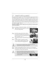
... to fully open position at approximately 100 degrees. Rotate the load plate to clear retention tab. Otherwise, the CPU will be placed if returning the motherboard for after service. 17 Step 1. Step 2. It is found. Rotate the load lever to handle and avoid kicking off the PnP cap. 2. Remove PnP Cap...
... to fully open position at approximately 100 degrees. Rotate the load plate to clear retention tab. Otherwise, the CPU will be placed if returning the motherboard for after service. 17 Step 1. Step 2. It is found. Rotate the load lever to handle and avoid kicking off the PnP cap. 2. Remove PnP Cap...
User Manual
Page 19
... the CPU fan to the CPU_FAN connector (CPU_FAN1, see page 13, No. 1). Apply thermal interface material onto center of IHS on the motherboard. Fan cables on fastener caps with fan operation or contact other . Step 1. Repeat with the CPU fan connector on the socket surface. Place... the heatsink onto the socket. Ensure that this motherboard supports Combo Cooler Option (C.C.O.), which provides the exible option to adopt three different CPU cooler types, Socket LGA 775, LGA 1155 and LGA ...
... the CPU fan to the CPU_FAN connector (CPU_FAN1, see page 13, No. 1). Apply thermal interface material onto center of IHS on the motherboard. Fan cables on fastener caps with fan operation or contact other . Step 1. Repeat with the CPU fan connector on the socket surface. Place... the heatsink onto the socket. Ensure that this motherboard supports Combo Cooler Option (C.C.O.), which provides the exible option to adopt three different CPU cooler types, Socket LGA 775, LGA 1155 and LGA ...

User Manual
Page 20
... 5. If only one memory module or three memory modules are installed in the DDR3 DIMM slots on this motherboard, it is not allowed to install them on this motherboard. otherwise, this motherboard. 20 Black slots; Dual Channel Memory Configurations DDR3_A1 DDR3_A2 DDR3_B1 DDR3_B2 (Black Slot) (Black Slot...in Dual Channel B (DDR3_A2 and DDR3_ B2; Populated - Some DDR3 1GB double-sided DIMMs with 16 chips may not work on this motherboard and DIMM may refer to install four DDR3 DIMMs for example, installing a pair of memory modules in DDR3_A1 and DDR3_A2, it is recommended...
... 5. If only one memory module or three memory modules are installed in the DDR3 DIMM slots on this motherboard, it is not allowed to install them on this motherboard. otherwise, this motherboard. 20 Black slots; Dual Channel Memory Configurations DDR3_A1 DDR3_A2 DDR3_B1 DDR3_B2 (Black Slot) (Black Slot...in Dual Channel B (DDR3_A2 and DDR3_ B2; Populated - Some DDR3 1GB double-sided DIMMs with 16 chips may not work on this motherboard and DIMM may refer to install four DDR3 DIMMs for example, installing a pair of memory modules in DDR3_A1 and DDR3_A2, it is recommended...

User Manual
Page 21
.... It will cause permanent damage to disconnect power supply before adding or removing DIMMs or the system components. Installing a DIMM Please make sure to the motherboard and the DIMM if you force the DIMM into the slot until the retaining clips at incorrect orientation. Step 2. Unlock a DIMM slot by pressing the...
.... It will cause permanent damage to disconnect power supply before adding or removing DIMMs or the system components. Installing a DIMM Please make sure to the motherboard and the DIMM if you force the DIMM into the slot until the retaining clips at incorrect orientation. Step 2. Unlock a DIMM slot by pressing the...
User Manual
Page 22
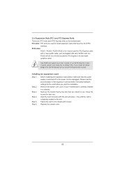
... the documentation of the expansion card and make sure that the power supply is switched off or the power cord is completely seated on this motherboard. If you start the installation. Installing an expansion card Step 1. Step 4. Remove the bracket facing the slot that you intend to use . Step 3. ...before you install the Sandy Bridge CPU, the PCI Express will run the PCI Express in a chassis). Remove the system unit cover (if your motherboard is used for PCI Express cards with the slot and press rmly until the card is unplugged. Step 6. To run only at PCI Express Gen...
... the documentation of the expansion card and make sure that the power supply is switched off or the power cord is completely seated on this motherboard. If you start the installation. Installing an expansion card Step 1. Step 4. Remove the bracket facing the slot that you intend to use . Step 3. ...before you install the Sandy Bridge CPU, the PCI Express will run the PCI Express in a chassis). Remove the system unit cover (if your motherboard is used for PCI Express cards with the slot and press rmly until the card is unplugged. Step 6. To run only at PCI Express Gen...

User Manual
Page 23
... your system boots. D-Sub, DVI-D and HDMI monitors cannot be enabled at the same time. 2.7 Dual Monitor and Surround Display Features Dual Monitor Feature This motherboard supports dual monitor feature. With the internal VGA output support (DVI-D, D-Sub and HDMI), you haven't installed onboard VGA driver yet, please install onboard VGA...-D, D-sub and HDMI can only choose the combination: DVI-D + HDMI, DVI-D + D-Sub, or HDMI + D-Sub. 23 You can drive same or different display contents. This motherboard also provides independent display controllers for DVI-D, D-Sub and HDMI to this...
... your system boots. D-Sub, DVI-D and HDMI monitors cannot be enabled at the same time. 2.7 Dual Monitor and Surround Display Features Dual Monitor Feature This motherboard supports dual monitor feature. With the internal VGA output support (DVI-D, D-Sub and HDMI), you haven't installed onboard VGA driver yet, please install onboard VGA...-D, D-sub and HDMI can only choose the combination: DVI-D + HDMI, DVI-D + D-Sub, or HDMI + D-Sub. 23 You can drive same or different display contents. This motherboard also provides independent display controllers for DVI-D, D-Sub and HDMI to this...

User Manual
Page 24
... function when the add-on VGA card is no need to the corresponding connectors of surround display feature. F. G. Surround Display Feature This motherboard supports surround display upgrade. Then connect other monitor cables to install them again. 5. For Windows® XP / XP 64-bit OS:...monitors with your primary monitor, and then select "Primary". Click the "Identify" button to the steps below. Click "Extend my Windows desktop onto this motherboard. 4. Click "Apply" or "OK" to enter UEFI setup. Repeat steps C through E for details. 2. Enter "Onboard VGA Share Memory" option...
... function when the add-on VGA card is no need to the corresponding connectors of surround display feature. F. G. Surround Display Feature This motherboard supports surround display upgrade. Then connect other monitor cables to install them again. 5. For Windows® XP / XP 64-bit OS:...monitors with your primary monitor, and then select "Primary". Click the "Identify" button to the steps below. Click "Extend my Windows desktop onto this motherboard. 4. Click "Apply" or "OK" to enter UEFI setup. Repeat steps C through E for details. 2. Enter "Onboard VGA Share Memory" option...

User Manual
Page 25
D. To use HDCP function with this motherboard, you would like to use. Please refer to a compliant display. such as it is highly recommended that the HDTV or LCD monitor you can enjoy ... Content Protection, a speci cation developed by the number three and four. 6. Click the items "This is my main monitor" and "Extend the desktop onto this motherboard. Click and drag the display icons to positions representing the physical setup of intercepting digital data midstream between the video source, or transmitter - HDCP Function...
D. To use HDCP function with this motherboard, you would like to use. Please refer to a compliant display. such as it is highly recommended that the HDTV or LCD monitor you can enjoy ... Content Protection, a speci cation developed by the number three and four. 6. Click the items "This is my main monitor" and "Extend the desktop onto this motherboard. Click and drag the display icons to positions representing the physical setup of intercepting digital data midstream between the video source, or transmitter - HDCP Function...

User Manual
Page 26
... the front USB cable to connect it before you boot the system. * ASRock Smart Remote is only supported by some of the chassis on ASRock motherboard. 2.8 ASRock Smart Remote Installation Guide ASRock Smart Remote is only used for front USB only. GND IRTX IRRX ATX+...5VSB Install Multi-Angle CIR Receiver to ASRock website for ASRock motherboard with most of ASRock motherboards. Please make PP+ GND DUMMY ...
... the front USB cable to connect it before you boot the system. * ASRock Smart Remote is only supported by some of the chassis on ASRock motherboard. 2.8 ASRock Smart Remote Installation Guide ASRock Smart Remote is only used for front USB only. GND IRTX IRRX ATX+...5VSB Install Multi-Angle CIR Receiver to ASRock website for ASRock motherboard with most of ASRock motherboards. Please make PP+ GND DUMMY ...

User Manual
Page 28
...2.0 ports on the I/O panel, there are NOT jumpers. Placing jumper caps over these headers and connectors. Either end of the motherboard! The current SATA3 interface allows up to 6.0 Gb/s data transfer rate. 2.10 Onboard Headers and Connectors Onboard headers and connectors ...are three USB 2.0 headers on this motherboard. Serial ATA3 Connectors (SATA3_0: see p.13, No. 11) (SATA3_1: see p.13, No. 9) SATA3_1 SATA3_0 Serial ATA (SATA) Data Cable...
...2.0 ports on the I/O panel, there are NOT jumpers. Placing jumper caps over these headers and connectors. Either end of the motherboard! The current SATA3 interface allows up to 6.0 Gb/s data transfer rate. 2.10 Onboard Headers and Connectors Onboard headers and connectors ...are three USB 2.0 headers on this motherboard. Serial ATA3 Connectors (SATA3_0: see p.13, No. 11) (SATA3_1: see p.13, No. 9) SATA3_1 SATA3_0 Serial ATA (SATA) Data Cable...


