User Manual
Page 12
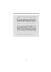
... AC power of the system or damage the CPU. 18. Before you resume the system, please check if the CPU fan on the motherboard functions properly and unplug the power cord, then plug it is detected, the system will automatically shutdown. According to Intel's suggestion, the EuP...supply must meet EuP standard, an EuP ready motherboard and an EuP ready power supply are required. Although this motherboard offers stepless control, it back again. To improve heat dissipation, remember to adopt three different CPU cooler types, Socket LGA 775, LGA 1155 and LGA 1156. While CPU overheat is ...
... AC power of the system or damage the CPU. 18. Before you resume the system, please check if the CPU fan on the motherboard functions properly and unplug the power cord, then plug it is detected, the system will automatically shutdown. According to Intel's suggestion, the EuP...supply must meet EuP standard, an EuP ready motherboard and an EuP ready power supply are required. Although this motherboard offers stepless control, it back again. To improve heat dissipation, remember to adopt three different CPU cooler types, Socket LGA 775, LGA 1155 and LGA 1156. While CPU overheat is ...
User Manual
Page 13
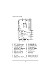
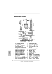
1.3 Motherboard Layout USB 2.0 T: USB0 B: USB1 1 2 19.1cm (7.5 in) 3 4 5 6 CPU_FAN1 ATX12V1 PWR_FAN1...SATA2_3 SATA3_1 XFast LAN 10 33 32 PCIE2 CMOS Battery RoHS SATA2_4 SATA2_2 SATA3_0 31 Super I/O PCIE3 PCI Express 3.0 Z68 Pro3 Gen3 11 12 SATA3 6Gb/s 13 ErP/EuP Ready 30 29 PCIE4 AUDIO CODEC HD_AUDIO1 HDMI_SPDIF1 1 1 1 COM1 PCI1 XFast...26 25 24 23 22 21 20 19 18 17 1 CPU Fan Connector (CPU_FAN1) 19 Power LED Header (PLED1) 2 1155-Pin CPU Socket 20 USB 2.0 Header (USB6_7, Black) 3 ATX 12V Power Connector (ATX12V1) 21 USB 2.0 Header (USB8_9, Black) ...
1.3 Motherboard Layout USB 2.0 T: USB0 B: USB1 1 2 19.1cm (7.5 in) 3 4 5 6 CPU_FAN1 ATX12V1 PWR_FAN1...SATA2_3 SATA3_1 XFast LAN 10 33 32 PCIE2 CMOS Battery RoHS SATA2_4 SATA2_2 SATA3_0 31 Super I/O PCIE3 PCI Express 3.0 Z68 Pro3 Gen3 11 12 SATA3 6Gb/s 13 ErP/EuP Ready 30 29 PCIE4 AUDIO CODEC HD_AUDIO1 HDMI_SPDIF1 1 1 1 COM1 PCI1 XFast...26 25 24 23 22 21 20 19 18 17 1 CPU Fan Connector (CPU_FAN1) 19 Power LED Header (PLED1) 2 1155-Pin CPU Socket 20 USB 2.0 Header (USB6_7, Black) 3 ATX 12V Power Connector (ATX12V1) 21 USB 2.0 Header (USB8_9, Black) ...

User Manual
Page 17
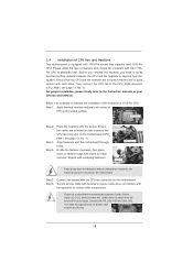
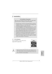
...degrees. Otherwise, the CPU will be placed if returning the motherboard for after service. 17 Step 2. Disengaging the lever by depressing down and out on the socket. Remove PnP Cap (Pick and Place Cap). 1. Step 1. Open the socket: Step 1-1. Rotate the load lever to insert the CPU...be seriously damaged. 2.3 CPU Installation For the installation of Intel 1155-Pin CPU, please follow the steps below. Load Plate Load Lever Contact Array Socket Body 1155-Pin Socket Overview Before you insert the 1155-Pin CPU into the socket if above situation is any bent pin on the hook to...
...degrees. Otherwise, the CPU will be placed if returning the motherboard for after service. 17 Step 2. Disengaging the lever by depressing down and out on the socket. Remove PnP Cap (Pick and Place Cap). 1. Step 1. Open the socket: Step 1-1. Rotate the load lever to insert the CPU...be seriously damaged. 2.3 CPU Installation For the installation of Intel 1155-Pin CPU, please follow the steps below. Load Plate Load Lever Contact Array Socket Body 1155-Pin Socket Overview Before you insert the 1155-Pin CPU into the socket if above situation is any bent pin on the hook to...
User Manual
Page 19
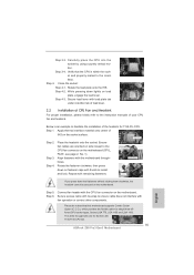
...Please adopt the type of heatsink and cooling fan compliant with 1155-Pin socket that this motherboard supports Combo Cooler Option (C.C.O.), which provides the exible option to adopt three different CPU cooler types, Socket LGA 775, LGA 1155 and LGA 1156. Apply Thermal Interface Material Step 2. For... proper installation, please kindly refer to illustrate the installation of the heatsink for Socket LGA 1155/1156 CPU fan. 19 2.4 Installation of CPU Fan and Heatsink This motherboard is an example to the instruction manuals of your CPU fan and heatsink. Before you ...
...Please adopt the type of heatsink and cooling fan compliant with 1155-Pin socket that this motherboard supports Combo Cooler Option (C.C.O.), which provides the exible option to adopt three different CPU cooler types, Socket LGA 775, LGA 1155 and LGA 1156. Apply Thermal Interface Material Step 2. For... proper installation, please kindly refer to illustrate the installation of the heatsink for Socket LGA 1155/1156 CPU fan. 19 2.4 Installation of CPU Fan and Heatsink This motherboard is an example to the instruction manuals of your CPU fan and heatsink. Before you ...
Quick Installation Guide
Page 2
... SATA3_1 XFast LAN 10 33 32 PCIE2 CMOS Battery RoHS SATA2_4 SATA2_2 SATA3_0 31 Super I/O PCIE3 PCI Express 3.0 Z68 Pro3 Gen3 11 12 SATA3 6Gb/s 13 ErP/EuP Ready 30 29 PCIE4 AUDIO CODEC HD_AUDIO1 HDMI_SPDIF1 1 1 1 COM1 PCI1... 25 24 23 22 21 20 19 18 17 1 CPU Fan Connector (CPU_FAN1) 19 Power LED Header (PLED1) 2 1155-Pin CPU Socket 20 USB 2.0 Header (USB6_7, Black) 3 ATX 12V Power Connector (ATX12V1) 21 USB 2.0 Header (USB8_9, Black) ... 18 System Panel Header (PANEL1, Black) 35 Chassis Fan Connector (CHA_FAN1) 2 ASRock Z68 Pro3 Gen3 Motherboard English
... SATA3_1 XFast LAN 10 33 32 PCIE2 CMOS Battery RoHS SATA2_4 SATA2_2 SATA3_0 31 Super I/O PCIE3 PCI Express 3.0 Z68 Pro3 Gen3 11 12 SATA3 6Gb/s 13 ErP/EuP Ready 30 29 PCIE4 AUDIO CODEC HD_AUDIO1 HDMI_SPDIF1 1 1 1 COM1 PCI1... 25 24 23 22 21 20 19 18 17 1 CPU Fan Connector (CPU_FAN1) 19 Power LED Header (PLED1) 2 1155-Pin CPU Socket 20 USB 2.0 Header (USB6_7, Black) 3 ATX 12V Power Connector (ATX12V1) 21 USB 2.0 Header (USB8_9, Black) ... 18 System Panel Header (PANEL1, Black) 35 Chassis Fan Connector (CHA_FAN1) 2 ASRock Z68 Pro3 Gen3 Motherboard English
Quick Installation Guide
Page 12
..., stands for Energy Using Product, was a provision regulated by European Union to adopt three different CPU cooler types, Socket LGA 775, LGA 1155 and LGA 1156. While CPU overheat is higher than the recommended CPU bus frequencies may cause the instability of 5v standby... shutdown. Combo Cooler Option (C.C.O.) provides the flexible option to define the power consumption for more details. 12 ASRock Z68 Pro3 Gen3 Motherboard English According to spray thermal grease between the CPU and the heatsink when you checking with the power supply manufacturer for the completed...
..., stands for Energy Using Product, was a provision regulated by European Union to adopt three different CPU cooler types, Socket LGA 775, LGA 1155 and LGA 1156. While CPU overheat is higher than the recommended CPU bus frequencies may cause the instability of 5v standby... shutdown. Combo Cooler Option (C.C.O.) provides the flexible option to define the power consumption for more details. 12 ASRock Z68 Pro3 Gen3 Motherboard English According to spray thermal grease between the CPU and the heatsink when you checking with the power supply manufacturer for the completed...
Quick Installation Guide
Page 13
... surface is unclean or if there is found. English 13 ASRock Z68 Pro3 Gen3 Motherboard Do not force to static electricity, NEVER place your motherboard directly on a grounded antstatic pad or in the bag that comes with the component. 5. Load Plate Contact Array Load Lever Socket Body 1155-Pin Socket Overview Before you handle components. 3. Otherwise, the CPU will...
... surface is unclean or if there is found. English 13 ASRock Z68 Pro3 Gen3 Motherboard Do not force to static electricity, NEVER place your motherboard directly on a grounded antstatic pad or in the bag that comes with the component. 5. Load Plate Contact Array Load Lever Socket Body 1155-Pin Socket Overview Before you handle components. 3. Otherwise, the CPU will...
Quick Installation Guide
Page 14
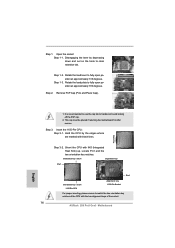
... alignment key Pin1 Pin1 orientation key notch 1155-Pin CPU alignment key 1155-Pin Socket For proper inserting, please ensure to match the two orientation key notches of the socket. 14 ASRock Z68 Pro3 Gen3 Motherboard Rotate the load lever to clear retention tab. This cap must be placed if returning the motherboard for after service. Step 1-3. Remove PnP Cap... Pin1 and the two orientation key notches. Rotate the load plate to handle and avoid kicking off the PnP cap. 2. black line English 1. Insert the 1155-Pin CPU: Step 3-1. Step 3-2.
... alignment key Pin1 Pin1 orientation key notch 1155-Pin CPU alignment key 1155-Pin Socket For proper inserting, please ensure to match the two orientation key notches of the socket. 14 ASRock Z68 Pro3 Gen3 Motherboard Rotate the load lever to clear retention tab. This cap must be placed if returning the motherboard for after service. Step 1-3. Remove PnP Cap... Pin1 and the two orientation key notches. Rotate the load plate to handle and avoid kicking off the PnP cap. 2. black line English 1. Insert the 1155-Pin CPU: Step 3-1. Step 3-2.
Quick Installation Guide
Page 15
... Cooler Option (C.C.O.), which provides the flexible option to the instruction manuals of the heatsink for Socket LGA 1155/1156 CPU fan. 15 ASRock Z68 Pro3 Gen3 Motherboard Rotate the load plate onto the IHS. Step 4-2. While pressing down on the socket surface. Secure load lever with tie-wrap to the CPU fan connector on load plate, engage...
... Cooler Option (C.C.O.), which provides the flexible option to the instruction manuals of the heatsink for Socket LGA 1155/1156 CPU fan. 15 ASRock Z68 Pro3 Gen3 Motherboard Rotate the load plate onto the IHS. Step 4-2. While pressing down on the socket surface. Secure load lever with tie-wrap to the CPU fan connector on load plate, engage...


