Intel Rapid Storage Guide
Page 12
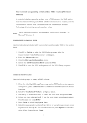
...; Rapid Storage Technology driver during POST, press Ctrl and i at the same time to enable RAID in System BIOS Use the instructions included with your motherboard to enter the option ROM user interface. 2. Select 1: Create RAID Volume and press Enter. 3.
...; Rapid Storage Technology driver during POST, press Ctrl and i at the same time to enable RAID in System BIOS Use the instructions included with your motherboard to enter the option ROM user interface. 2. Select 1: Create RAID Volume and press Enter. 3.

RAID Installation Guide
Page 2
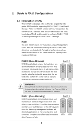
You may install SATA hard disks on SATA ports. 2 This section will guide you how to SATA Hard Disks Installation 1.1 Serial ATA (SATA) Hard Disks Installation Intel chipset supports Serial ATA (SATA) hard disks with RAID functions, including RAID 0, RAID 1, RAID 5, RAID 10 and Intel Rapid Storage. Guide to create RAID on this guide carefully according to the Intel southbridge chipset that your motherboard adopts. 1. Please read the RAID configurations in this motherboard for internal storage devices.
You may install SATA hard disks on SATA ports. 2 This section will guide you how to SATA Hard Disks Installation 1.1 Serial ATA (SATA) Hard Disks Installation Intel chipset supports Serial ATA (SATA) hard disks with RAID functions, including RAID 0, RAID 1, RAID 5, RAID 10 and Intel Rapid Storage. Guide to create RAID on this guide carefully according to the Intel southbridge chipset that your motherboard adopts. 1. Please read the RAID configurations in this motherboard for internal storage devices.
RAID Installation Guide
Page 3
... data from one drive fails. 3 WARNING!! For optimal performance, please install identical drives of the RAID 0 Disk will introduce the basic knowledge of RAID This motherboard adopts Intel southbridge chipset that optimizes two identical hard disk drives to read and write data in the other drive if one drive to the...
... data from one drive fails. 3 WARNING!! For optimal performance, please install identical drives of the RAID 0 Disk will introduce the basic knowledge of RAID This motherboard adopts Intel southbridge chipset that optimizes two identical hard disk drives to read and write data in the other drive if one drive to the...
RAID Installation Guide
Page 23
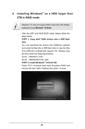
... than 2TB. STEP 1: Copy Intel® RAID drivers into a USB flash disk You can download the drivers from ASRock's website and unzip the files into a USB flash disk or copy the files from ASRock's motherboard support CD. (Please copy the files under the following directory: 32 bit: ..\i386\Win7_Intel.. 64-bit: ..\AMD64\Win7...
... than 2TB. STEP 1: Copy Intel® RAID drivers into a USB flash disk You can download the drivers from ASRock's website and unzip the files into a USB flash disk or copy the files from ASRock's motherboard support CD. (Please copy the files under the following directory: 32 bit: ..\i386\Win7_Intel.. 64-bit: ..\AMD64\Win7...
RAID Installation Guide
Page 25
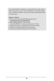
... 64-bit, install the hotfix kb2505454. (This may take about 5 minutes to fix this problem. Reboot your system. (It may take more time to install motherboard drivers and utilities. 25 Please start to boot into Windows® or install driver/utilities. E. Please request the hotfix KB2505454 through this link: http://support...
... 64-bit, install the hotfix kb2505454. (This may take about 5 minutes to fix this problem. Reboot your system. (It may take more time to install motherboard drivers and utilities. 25 Please start to boot into Windows® or install driver/utilities. E. Please request the hotfix KB2505454 through this link: http://support...
User Manual
Page 2
...you discard the Lithium battery in California, USA, please follow the related regulations in Perchlorate Best Management Practices (BMP) regulations passed by ASRock. Disclaimer: Specifications and information contained in any form or by the purchaser for identification or explanation and to the owners' benefit, without ..., transmitted, or translated in any means, except duplication of the FCC Rules. Version 1.0 Published March 2020 Copyright©2020 ASRock INC. Copyright Notice: No part of this motherboard contains Perchlorate, a toxic substance controlled in advance.
...you discard the Lithium battery in California, USA, please follow the related regulations in Perchlorate Best Management Practices (BMP) regulations passed by ASRock. Disclaimer: Specifications and information contained in any form or by the purchaser for identification or explanation and to the owners' benefit, without ..., transmitted, or translated in any means, except duplication of the FCC Rules. Version 1.0 Published March 2020 Copyright©2020 ASRock INC. Copyright Notice: No part of this motherboard contains Perchlorate, a toxic substance controlled in advance.
User Manual
Page 5
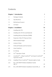
Contents Chapter 1 Introduction 1 1.1 Package Contents 1 1.2 Specifications 2 1.3 Motherboard Layout 9 1.4 I/O Panel 11 Chapter 2 Installation 14 2.1 Installing the CPU 15 2.2 Installing the CPU Fan and Heatsink 18 2.3 Installing Memory Modules (DIMM) 19 2.4 Expansion Slots (PCI ...
Contents Chapter 1 Introduction 1 1.1 Package Contents 1 1.2 Specifications 2 1.3 Motherboard Layout 9 1.4 I/O Panel 11 Chapter 2 Installation 14 2.1 Installing the CPU 15 2.2 Installing the CPU Fan and Heatsink 18 2.3 Installing Memory Modules (DIMM) 19 2.4 Expansion Slots (PCI ...
User Manual
Page 6
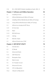
...) 52 Chapter 3 Software and Utilities Operation 56 3.1 Installing Drivers 56 3.2 ASRock Motherboard Utility (A-Tuning) 57 3.2.1 Installing ASRock Motherboard Utility (A-Tuning) 57 3.2.2 Using ASRock Motherboard Utility (A-Tuning) 57 3.3 ASRock Live Update & APP Shop 60 3.3.1 UI Overview 60 3.3.2 Apps 61 3.3.3 BIOS & Drivers 64 3.3.4 Setting 65 3.4 Nahimic Audio 66 3.5 ASRock Polychrome SYNC 67 Chapter 4 UEFI SETUP UTILITY 70 4.1 Introduction 70 4.2 EZ...
...) 52 Chapter 3 Software and Utilities Operation 56 3.1 Installing Drivers 56 3.2 ASRock Motherboard Utility (A-Tuning) 57 3.2.1 Installing ASRock Motherboard Utility (A-Tuning) 57 3.2.2 Using ASRock Motherboard Utility (A-Tuning) 57 3.3 ASRock Live Update & APP Shop 60 3.3.1 UI Overview 60 3.3.2 Apps 61 3.3.3 BIOS & Drivers 64 3.3.4 Setting 65 3.4 Nahimic Audio 66 3.5 ASRock Polychrome SYNC 67 Chapter 4 UEFI SETUP UTILITY 70 4.1 Introduction 70 4.2 EZ...

User Manual
Page 8
... and endurance. ASRock website http://www.asrock.com. 1.1 Package Contents • ASRock Z490 Taichi Motherboard (ATX Form Factor) • ASRock Z490 Taichi Quick Installation Guide • ASRock Z490 Taichi Support CD • 4 x Serial ATA (SATA) Data Cables (Optional) • 1 x ASRock SLI_HB_Bridge_2S Card • 1 x ASRock WiFi 2.4/5 GHz Antenna • 1 x ASRock Screwdriver (Optional) • 3 x Screws for M.2 Sockets (Optional) • 2 x Standoffs for purchasing ASRock Z490 Taichi motherboard, a reliable motherboard produced under ASRock's consistently stringent...
... and endurance. ASRock website http://www.asrock.com. 1.1 Package Contents • ASRock Z490 Taichi Motherboard (ATX Form Factor) • ASRock Z490 Taichi Quick Installation Guide • ASRock Z490 Taichi Support CD • 4 x Serial ATA (SATA) Data Cables (Optional) • 1 x ASRock SLI_HB_Bridge_2S Card • 1 x ASRock WiFi 2.4/5 GHz Antenna • 1 x ASRock Screwdriver (Optional) • 3 x Screws for M.2 Sockets (Optional) • 2 x Standoffs for purchasing ASRock Z490 Taichi motherboard, a reliable motherboard produced under ASRock's consistently stringent...
User Manual
Page 16
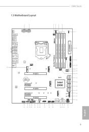
1.3 Motherboard Layout 1 2 BIOS _FB1 M2_WIFI_2 AT X 1 2 V 1 AT X 1 2 V 2 Z490 Taichi 34 5 6 CPU_FAN2/WP_3A CPU_FAN1 ADDR_LED2 7 1 D I S P L AY 1 HDMI1 AT X P W R 1 Z49O Taichi DDR4_A1 (64 bit, 288-pin module) DDR4_A2 (64 bit, 288-pin module) DDR4_B1 (64 ...CT23 PCIE2 PCIE3 CT42 M2_4 M2_2 USB3_8_9 RGB_LED2 1 1 1 USB3_6_7 CHA_FAN5/WP USB31_TC_2 S ATA 3 _ 0 _ 1 S ATA 3 _ 2 _ 3 RoHS Intel Z490 SATA3_A1_A2 SATA3_4_5 CT35 CT34 PCIE4 PCIE5 1 1 HD_AUDIO1 ADDR_LED1 1 T B1 RGB_LED1 1 CHA_FAN4/WP CHA_FAN2/WP BIOS ROM 1 CLRMOS1 CT33 CT32 CT31 CHA_FAN6 /WP SPI_TPM_J1 1...
1.3 Motherboard Layout 1 2 BIOS _FB1 M2_WIFI_2 AT X 1 2 V 1 AT X 1 2 V 2 Z490 Taichi 34 5 6 CPU_FAN2/WP_3A CPU_FAN1 ADDR_LED2 7 1 D I S P L AY 1 HDMI1 AT X P W R 1 Z49O Taichi DDR4_A1 (64 bit, 288-pin module) DDR4_A2 (64 bit, 288-pin module) DDR4_B1 (64 ...CT23 PCIE2 PCIE3 CT42 M2_4 M2_2 USB3_8_9 RGB_LED2 1 1 1 USB3_6_7 CHA_FAN5/WP USB31_TC_2 S ATA 3 _ 0 _ 1 S ATA 3 _ 2 _ 3 RoHS Intel Z490 SATA3_A1_A2 SATA3_4_5 CT35 CT34 PCIE4 PCIE5 1 1 HD_AUDIO1 ADDR_LED1 1 T B1 RGB_LED1 1 CHA_FAN4/WP CHA_FAN2/WP BIOS ROM 1 CLRMOS1 CT33 CT32 CT31 CHA_FAN6 /WP SPI_TPM_J1 1...

User Manual
Page 20
Bluetooth v5.1 standard features Smart Ready technology that offers support for PCs. Z490 Taichi 1.5 WiFi-802.11ax Module and ASRock WiFi 2.4/5 GHz Antenna WiFi-802.11ax + BT Module This motherboard comes with an exclusive WiFi 802.11 a/b/g/n/ax + BT v5.1 module (pre-installed on the rear I/O panel) that adds a whole new class of functionality into... WiFi 802.11 a/b/ g/n/ax connectivity standards and Bluetooth v5.1. WiFi + BT module is an easy-touse wireless local area network (WLAN) adapter to the environment. ASRock WiFi 2.4/5 GHz Antenna 13 English
Bluetooth v5.1 standard features Smart Ready technology that offers support for PCs. Z490 Taichi 1.5 WiFi-802.11ax Module and ASRock WiFi 2.4/5 GHz Antenna WiFi-802.11ax + BT Module This motherboard comes with an exclusive WiFi 802.11 a/b/g/n/ax + BT v5.1 module (pre-installed on the rear I/O panel) that adds a whole new class of functionality into... WiFi 802.11 a/b/ g/n/ax connectivity standards and Bluetooth v5.1. WiFi + BT module is an easy-touse wireless local area network (WLAN) adapter to the environment. ASRock WiFi 2.4/5 GHz Antenna 13 English
User Manual
Page 21
...Pre-installation Precautions Take note of your motherboard directly on a grounded anti-static pad or in the bag that the motherboard fits into it. Chapter 2 Installation This is an ATX form factor motherboard. Before you install the motherboard, study the configuration of the following ...precautions before you uninstall any motherboard settings. • Make sure to the chassis...
...Pre-installation Precautions Take note of your motherboard directly on a grounded anti-static pad or in the bag that the motherboard fits into it. Chapter 2 Installation This is an ATX form factor motherboard. Before you install the motherboard, study the configuration of the following ...precautions before you uninstall any motherboard settings. • Make sure to the chassis...
User Manual
Page 24
The cover must be placed if you wish to return the motherboard for after service. 17 English Z490 Taichi Please save and replace the cover if the processor is removed.
The cover must be placed if you wish to return the motherboard for after service. 17 English Z490 Taichi Please save and replace the cover if the processor is removed.
User Manual
Page 26
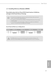
... Populated DDR4_A2 Populated Populated DDR4_B1 Populated DDR4_B2 Populated Populated The DIMM only fits in one or three memory module installed. 3. Z490 Taichi 2.3 Installing Memory Modules (DIMM) This motherboard provides four 288-pin DDR4 (Double Data Rate 4) DIMM slots, and supports Dual Channel Memory Technology. 1. For dual channel... configuration, you force the DIMM into a DDR4 slot; It will cause permanent damage to the motherboard and the DIMM if you always need to install a DDR, DDR2 or DDR3 memory module into the slot at incorrect orientation.
... Populated DDR4_A2 Populated Populated DDR4_B1 Populated DDR4_B2 Populated Populated The DIMM only fits in one or three memory module installed. 3. Z490 Taichi 2.3 Installing Memory Modules (DIMM) This motherboard provides four 288-pin DDR4 (Double Data Rate 4) DIMM slots, and supports Dual Channel Memory Technology. 1. For dual channel... configuration, you force the DIMM into a DDR4 slot; It will cause permanent damage to the motherboard and the DIMM if you always need to install a DDR, DDR2 or DDR3 memory module into the slot at incorrect orientation.

User Manual
Page 28
... Express x1 lane width cards. PCIE2 (PCIe 3.0 x1 slot) is used for the card before you start the installation. Z490 Taichi 2.4 Expansion Slots (PCI Express Slots) There are 5 PCI Express slots on the motherboard. Please read the documentation of the expansion card and make sure that the power supply is switched off or... or SLITM x8 Mode x8 N/A Three Graphics Cards in 3-Way CrossFireXTM Mode x8 x8 x4 For a better thermal environment, please connect a chassis fan to the motherboard's chassis fan connector (CHA_FAN1~6/WP) when using multiple graphics cards.
... Express x1 lane width cards. PCIE2 (PCIe 3.0 x1 slot) is used for the card before you start the installation. Z490 Taichi 2.4 Expansion Slots (PCI Express Slots) There are 5 PCI Express slots on the motherboard. Please read the documentation of the expansion card and make sure that the power supply is switched off or... or SLITM x8 Mode x8 N/A Three Graphics Cards in 3-Way CrossFireXTM Mode x8 x8 x4 For a better thermal environment, please connect a chassis fan to the motherboard's chassis fan connector (CHA_FAN1~6/WP) when using multiple graphics cards.

User Manual
Page 31
... and negative pins before connecting the cables. English 24 Press the reset button to restart the computer if the computer freezes and fails to the motherboard. You may differ by chassis.
... and negative pins before connecting the cables. English 24 Press the reset button to restart the computer if the computer freezes and fails to the motherboard. You may differ by chassis.
User Manual
Page 32
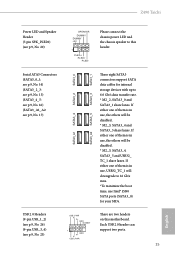
... lanes. Each USB 2.0 header can support two ports. 25 English If either one of them is in use Intel® Z490 SATA ports (SATA3_0) for internal storage devices with up to this motherboard. Z490 Taichi Power LED and Speaker Header (7-pin SPK_PLED1) (see p.9, No. 25) USB_PWR PP+ GND DUMMY 1 GND P+ PUSB_PWR There are two...
... lanes. Each USB 2.0 header can support two ports. 25 English If either one of them is in use Intel® Z490 SATA ports (SATA3_0) for internal storage devices with up to this motherboard. Z490 Taichi Power LED and Speaker Header (7-pin SPK_PLED1) (see p.9, No. 25) USB_PWR PP+ GND DUMMY 1 GND P+ PUSB_PWR There are two...
User Manual
Page 33
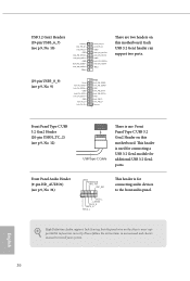
... Audio supports Jack Sensing, but the panel wire on the chassis must support HDA to install your system. Vbus There are two headers on this motherboard. Front Panel Audio Header (9-pin HD_AUDIO1) (see p.9, No. 34) GND PRESENCE# MIC_RET OUT_RET 1 OUT2_L J_SENSE OUT2_R MIC2_R MIC2_L This header is for additional USB 3.2 Gen2... audio panel. USB 3.2 Gen1 Headers (19-pin USB3_6_7) (see p.9, No. 12) USB Type-C Cable There is one Front Panel Type C USB 3.2 Gen2 Header on this motherboard. GND IntA_PB_SSTX+ IntA_PB_SSTX-
... Audio supports Jack Sensing, but the panel wire on the chassis must support HDA to install your system. Vbus There are two headers on this motherboard. Front Panel Audio Header (9-pin HD_AUDIO1) (see p.9, No. 34) GND PRESENCE# MIC_RET OUT_RET 1 OUT2_L J_SENSE OUT2_R MIC2_R MIC2_L This header is for additional USB 3.2 Gen2... audio panel. USB 3.2 Gen1 Headers (19-pin USB3_6_7) (see p.9, No. 12) USB Type-C Cable There is one Front Panel Type C USB 3.2 Gen2 Header on this motherboard. GND IntA_PB_SSTX+ IntA_PB_SSTX-
User Manual
Page 34
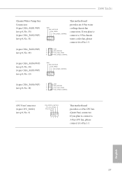
... p.9, No. 18) 3 4 GND FAN_VOLTAGE CHA_FAN_SPEED FAN_SPEED_CONTROL CPU Fan Connector (4-pin CPU_FAN1) (see p.9, No. 19) GND FAN_VOLTAGE FAN_SPEED FAN_SPEED_CONTROL 1 2 34 This motherboard provides six 4-Pin water cooling chassis fan connectors. English 27 Z490 Taichi Chassis/Water Pump Fan Connectors (4-pin CHA_FAN1/WP) (see p.9, No. 35) (4-pin CHA_FAN2/WP) (see p.9, No. 31) (4-pin CHA_FAN3/WP...
... p.9, No. 18) 3 4 GND FAN_VOLTAGE CHA_FAN_SPEED FAN_SPEED_CONTROL CPU Fan Connector (4-pin CPU_FAN1) (see p.9, No. 19) GND FAN_VOLTAGE FAN_SPEED FAN_SPEED_CONTROL 1 2 34 This motherboard provides six 4-Pin water cooling chassis fan connectors. English 27 Z490 Taichi Chassis/Water Pump Fan Connectors (4-pin CHA_FAN1/WP) (see p.9, No. 35) (4-pin CHA_FAN2/WP) (see p.9, No. 31) (4-pin CHA_FAN3/WP...

User Manual
Page 35
... install the Thunderbolt™ AIC card to this connector. 1 English Thunderbolt AIC Connectors (5-pin TB1) (see p.9, No. 2) 1 13 8 5 4 1 This motherboard provides a 24-pin ATX power connector. To use a 4-pin ATX power supply, please plug it to ATX12V2 is optional. *Warning: Please make sure that the... power cable connected is for the CPU and not the graphics card. This motherboard provides two 8-pin ATX 12V power connectors. CPU/Water Pump Fan Connector (4-pin CPU_FAN2/ WP_3A) (see p.9, No. 4) FAN_SPEED_CONTROL CPU_FAN_SPEED FAN_VOLTAGE...
... install the Thunderbolt™ AIC card to this connector. 1 English Thunderbolt AIC Connectors (5-pin TB1) (see p.9, No. 2) 1 13 8 5 4 1 This motherboard provides a 24-pin ATX power connector. To use a 4-pin ATX power supply, please plug it to ATX12V2 is optional. *Warning: Please make sure that the... power cable connected is for the CPU and not the graphics card. This motherboard provides two 8-pin ATX 12V power connectors. CPU/Water Pump Fan Connector (4-pin CPU_FAN2/ WP_3A) (see p.9, No. 4) FAN_SPEED_CONTROL CPU_FAN_SPEED FAN_VOLTAGE...


