
Intel Rapid Storage Guide
Page 12
Enable RAID in System BIOS Use the instructions included with your motherboard to enter the BIOS Setup program after the Power-On-Self-Test (POST) memory test begins. 2. Click F2 or Delete to enable RAID in the ...
Enable RAID in System BIOS Use the instructions included with your motherboard to enter the BIOS Setup program after the Power-On-Self-Test (POST) memory test begins. 2. Click F2 or Delete to enable RAID in the ...

RAID Installation Guide
Page 2
Guide to the Intel southbridge chipset that your motherboard adopts. 1. This section will guide you how to create RAID on this guide carefully according to SATA Hard Disks Installation 1.1 Serial ATA (SATA) Hard Disks Installation Intel chipset supports Serial ATA (SATA) hard disks with RAID functions, including RAID 0, RAID 1, RAID 5, RAID 10 and Intel Rapid Storage. Please read the RAID configurations in this motherboard for internal storage devices. You may install SATA hard disks on SATA ports. 2
Guide to the Intel southbridge chipset that your motherboard adopts. 1. This section will guide you how to create RAID on this guide carefully according to SATA Hard Disks Installation 1.1 Serial ATA (SATA) Hard Disks Installation Intel chipset supports Serial ATA (SATA) hard disks with RAID functions, including RAID 0, RAID 1, RAID 5, RAID 10 and Intel Rapid Storage. Please read the RAID configurations in this motherboard for internal storage devices. You may install SATA hard disks on SATA ports. 2

RAID Installation Guide
Page 3
Guide to RAID Configurations 2.1 Introduction of RAID This motherboard adopts Intel southbridge chipset that copies and maintains an identical image of a single disk alone while the two hard disks perform the same work as ...
Guide to RAID Configurations 2.1 Introduction of RAID This motherboard adopts Intel southbridge chipset that copies and maintains an identical image of a single disk alone while the two hard disks perform the same work as ...

RAID Installation Guide
Page 23
... steps below. STEP 1: Copy Intel® RAID drivers into a USB flash disk You can download the drivers from ASRock's website and unzip the files into a USB flash disk or copy the files from ASRock's motherboard support CD. (Please copy the files under the following directory: 32 bit: ..\i386\Win7_Intel.. 64-bit: ..\AMD64\Win7...
... steps below. STEP 1: Copy Intel® RAID drivers into a USB flash disk You can download the drivers from ASRock's website and unzip the files into a USB flash disk or copy the files from ASRock's motherboard support CD. (Please copy the files under the following directory: 32 bit: ..\i386\Win7_Intel.. 64-bit: ..\AMD64\Win7...

RAID Installation Guide
Page 25
E. Please start to boot into Windows® or install driver/utilities. Disk volume > 2TB), it may take more time to install motherboard drivers and utilities. 25 Windows® 10 64-bit: A. Please request the hotfix KB2505454 through this problem, you install Windows® 10 64-bit on a ...
E. Please start to boot into Windows® or install driver/utilities. Disk volume > 2TB), it may take more time to install motherboard drivers and utilities. 25 Windows® 10 64-bit: A. Please request the hotfix KB2505454 through this problem, you install Windows® 10 64-bit on a ...

User Manual
Page 2
... related regulations in this documentation may or may apply, see www.dtsc.ca.gov/hazardouswaste/ perchlorate" ASRock Website: http://www.asrock.com ASRock assumes no event shall ASRock, its directors, officers, employees, or agents be reproduced, transcribed, transmitted, or translated in any language...purchaser for informational use only and subject to the contents of this documentation may not cause harmful interference, and (2) this motherboard contains Perchlorate, a toxic substance controlled in the documentation or product. This device complies with Part 15 of their respective...
... related regulations in this documentation may or may apply, see www.dtsc.ca.gov/hazardouswaste/ perchlorate" ASRock Website: http://www.asrock.com ASRock assumes no event shall ASRock, its directors, officers, employees, or agents be reproduced, transcribed, transmitted, or translated in any language...purchaser for informational use only and subject to the contents of this documentation may not cause harmful interference, and (2) this motherboard contains Perchlorate, a toxic substance controlled in the documentation or product. This device complies with Part 15 of their respective...

User Manual
Page 5
Contents Chapter 1 Introduction 1 1.1 Package Contents 1 1.2 Specifications 2 1.3 Motherboard Layout 7 1.4 I/O Panel 9 1.5 WiFi-802.11ac Module and ASRock WiFi 2.4/5 GHz Antennas 10 Chapter 2 Installation 12 2.1 Installing the CPU 13 2.2 Installing the CPU Fan and Heatsink 16 2.3 Installing Memory Modules (DIMM) 17 2.4 Expansion Slots (...
Contents Chapter 1 Introduction 1 1.1 Package Contents 1 1.2 Specifications 2 1.3 Motherboard Layout 7 1.4 I/O Panel 9 1.5 WiFi-802.11ac Module and ASRock WiFi 2.4/5 GHz Antennas 10 Chapter 2 Installation 12 2.1 Installing the CPU 13 2.2 Installing the CPU Fan and Heatsink 16 2.3 Installing Memory Modules (DIMM) 17 2.4 Expansion Slots (...

User Manual
Page 6
3.2 ASRock Motherboard Utility (Phantom Gaming Tuning) 38 3.3 ASRock Live Update & APP Shop 41 3.3.1 UI Overview 41 3.3.2 Apps 42 3.3.3 BIOS & Drivers 45 3.3.4 Setting 46 3.4 Nahimic Audio 47 3.5 ASRock Polychrome SYNC 48 Chapter 4 UEFI SETUP UTILITY 51 4.1 Introduction 51 4.2 EZ Mode 52 4.3 Advanced Mode 53 4.3.1 UEFI Menu Bar 53 4.3.2 Navigation Keys 54 4.4 Main Screen ...
3.2 ASRock Motherboard Utility (Phantom Gaming Tuning) 38 3.3 ASRock Live Update & APP Shop 41 3.3.1 UI Overview 41 3.3.2 Apps 42 3.3.3 BIOS & Drivers 45 3.3.4 Setting 46 3.4 Nahimic Audio 47 3.5 ASRock Polychrome SYNC 48 Chapter 4 UEFI SETUP UTILITY 51 4.1 Introduction 51 4.2 EZ Mode 52 4.3 Advanced Mode 53 4.3.1 UEFI Menu Bar 53 4.3.2 Navigation Keys 54 4.4 Main Screen ...
User Manual
Page 9
... updated version will be available on ASRock's website as well. ASRock website http://www.asrock.com. 1.1 Package Contents • ASRock Z490 Phantom Gaming 4/ac Motherboard (ATX Form Factor) • ASRock Z490 Phantom Gaming 4/ac Quick Installation Guide • ASRock Z490 Phantom Gaming 4/ac Support CD • 2 x Serial ATA (SATA) Data Cables (Optional) • 2 x ASRock WiFi 2.4/5 GHz Antennas (Optional) • 1 x Screw for purchasing ASRock Z490 Phantom Gaming 4/ac motherboard, a reliable motherboard produced under ASRock's consistently stringent quality control. In...
... updated version will be available on ASRock's website as well. ASRock website http://www.asrock.com. 1.1 Package Contents • ASRock Z490 Phantom Gaming 4/ac Motherboard (ATX Form Factor) • ASRock Z490 Phantom Gaming 4/ac Quick Installation Guide • ASRock Z490 Phantom Gaming 4/ac Support CD • 2 x Serial ATA (SATA) Data Cables (Optional) • 2 x ASRock WiFi 2.4/5 GHz Antennas (Optional) • 1 x Screw for purchasing ASRock Z490 Phantom Gaming 4/ac motherboard, a reliable motherboard produced under ASRock's consistently stringent quality control. In...

User Manual
Page 15
HDMI1 USB 2.0 T: USB_1 B: USB_2 PS2 Keyboard /Mouse 1.3 Motherboard Layout 1 2 ATX12V1 ATX12V2 Z490 Phantom Gaming 4/ac 34 56 CPU_FAN1 CPU_FAN2/WP 7 ADDR_LED2 8 1 1 RGB_LED2 BOOT CPU 9 DRAM VGA DDR4_A1 (64 bit, 288-pin module) DDR4_A2 (64 bit, ... B: USB31_TC_1 10 USB 3.2 Gen1 Top: T: USB3_1 B: USB3_2 RJ-45 CHA_FAN2/WP Top: LINE IN Center: FRONT Bottom: MIC IN PCIE1 32 Z490 PHANTOM GAMING 4/ac PCIE2 CHA_FAN1/WP USB3_3_4 11 1 12 13 SATA3_1 SATA3_0 M2_WIFI1 SUPER I/O WiFi-802.11ac M2_WIFI_CT1 Module 14 CMOS Battery Intel 15 SATA3_2 SATA3_3 PCIE3 AUDIO...
HDMI1 USB 2.0 T: USB_1 B: USB_2 PS2 Keyboard /Mouse 1.3 Motherboard Layout 1 2 ATX12V1 ATX12V2 Z490 Phantom Gaming 4/ac 34 56 CPU_FAN1 CPU_FAN2/WP 7 ADDR_LED2 8 1 1 RGB_LED2 BOOT CPU 9 DRAM VGA DDR4_A1 (64 bit, 288-pin module) DDR4_A2 (64 bit, ... B: USB31_TC_1 10 USB 3.2 Gen1 Top: T: USB3_1 B: USB3_2 RJ-45 CHA_FAN2/WP Top: LINE IN Center: FRONT Bottom: MIC IN PCIE1 32 Z490 PHANTOM GAMING 4/ac PCIE2 CHA_FAN1/WP USB3_3_4 11 1 12 13 SATA3_1 SATA3_0 M2_WIFI1 SUPER I/O WiFi-802.11ac M2_WIFI_CT1 Module 14 CMOS Battery Intel 15 SATA3_2 SATA3_3 PCIE3 AUDIO...

User Manual
Page 18
... Energy Technology and ensures extraordinary low power consumption for WiFi 802.11 a/b/g/n/ac connectivity standards and Bluetooth v5.0. 1.5 WiFi-802.11ac Module and ASRock WiFi 2.4/5 GHz Antennas WiFi-802.11ac + BT Module This motherboard comes with an exclusive WiFi 802.11 a/b/g/n/ac + BT v5.0 module that adds a whole new class of functionality into the...
... Energy Technology and ensures extraordinary low power consumption for WiFi 802.11 a/b/g/n/ac connectivity standards and Bluetooth v5.0. 1.5 WiFi-802.11ac Module and ASRock WiFi 2.4/5 GHz Antennas WiFi-802.11ac + BT Module This motherboard comes with an exclusive WiFi 802.11 a/b/g/n/ac + BT v5.0 module that adds a whole new class of functionality into the...

User Manual
Page 20
...ensure that comes with the components. • When placing screws to secure the motherboard to the chassis, please do not touch the ICs. • Whenever you install motherboard components or change any motherboard settings. • Make sure to use a grounded wrist strap or touch a...8226; Hold components by the edges and do not overtighten the screws! Before you install the motherboard, study the configuration of the following precautions before installing or removing the motherboard components. Also remember to unplug the power cord before you uninstall any components, place them ...
...ensure that comes with the components. • When placing screws to secure the motherboard to the chassis, please do not touch the ICs. • Whenever you install motherboard components or change any motherboard settings. • Make sure to use a grounded wrist strap or touch a...8226; Hold components by the edges and do not overtighten the screws! Before you install the motherboard, study the configuration of the following precautions before installing or removing the motherboard components. Also remember to unplug the power cord before you uninstall any components, place them ...

User Manual
Page 23
The cover must be placed if you wish to return the motherboard for after service. 15 English Z490 Phantom Gaming 4/ac Please save and replace the cover if the processor is removed.
The cover must be placed if you wish to return the motherboard for after service. 15 English Z490 Phantom Gaming 4/ac Please save and replace the cover if the processor is removed.

User Manual
Page 25
... Channel Memory Configuration Priority 1 2 DDR4_A1 Populated DDR4_A2 Populated Populated DDR4_B1 Populated DDR4_B2 Populated Populated The DIMM only fits in one or three memory module installed. 3. Z490 Phantom Gaming 4/ac 2.3 Installing Memory Modules (DIMM) This motherboard provides four 288-pin DDR4 (Double Data Rate 4) DIMM slots, and supports Dual Channel Memory Technology. 1. otherwise, this...
... Channel Memory Configuration Priority 1 2 DDR4_A1 Populated DDR4_A2 Populated Populated DDR4_B1 Populated DDR4_B2 Populated Populated The DIMM only fits in one or three memory module installed. 3. Z490 Phantom Gaming 4/ac 2.3 Installing Memory Modules (DIMM) This motherboard provides four 288-pin DDR4 (Double Data Rate 4) DIMM slots, and supports Dual Channel Memory Technology. 1. otherwise, this...
User Manual
Page 27
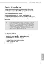
Z490 Phantom Gaming 4/ac 2.4 Expansion Slots (PCI Express Slots) There are 5 PCI Express slots on the motherboard. PCIe slots: PCIE1 (PCIe 3.0 x1 slot) is used for PCI Express x1 lane width cards. PCIE5 (PCIe 3.0 x1 slot) is used for PCI Express ... Single Graphics Card PCIE2 x16 PCIE4 N/A Two Graphics Cards in CrossFireXTM Mode x16 x4 For a better thermal environment, please connect a chassis fan to the motherboard's chassis fan connector (CHA_FAN1/WP, CHA_FAN2/WP, CHA_FAN3/WP or CHA_FAN4/WP) when using multiple graphics cards. Please read the documentation of the expansion card...
Z490 Phantom Gaming 4/ac 2.4 Expansion Slots (PCI Express Slots) There are 5 PCI Express slots on the motherboard. PCIe slots: PCIE1 (PCIe 3.0 x1 slot) is used for PCI Express x1 lane width cards. PCIE5 (PCIe 3.0 x1 slot) is used for PCI Express ... Single Graphics Card PCIE2 x16 PCIE4 N/A Two Graphics Cards in CrossFireXTM Mode x16 x4 For a better thermal environment, please connect a chassis fan to the motherboard's chassis fan connector (CHA_FAN1/WP, CHA_FAN2/WP, CHA_FAN3/WP or CHA_FAN4/WP) when using multiple graphics cards. Please read the documentation of the expansion card...
User Manual
Page 29
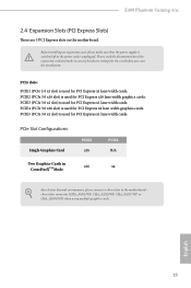
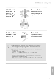
...front panel module to this header according to this header, make sure the wire assignments and the pin assignments are NOT jumpers. Z490 Phantom Gaming 4/ac 2.6 Onboard Headers and Connectors Onboard headers and connectors are matched correctly. Note the positive and negative pins before connecting the cables. ...activity LED on the chassis front panel. Press the reset button to restart the computer if the computer freezes and fails to the motherboard. A front panel module mainly consists of power button, reset button, power LED, hard drive activity LED, speaker and etc. ...
...front panel module to this header according to this header, make sure the wire assignments and the pin assignments are NOT jumpers. Z490 Phantom Gaming 4/ac 2.6 Onboard Headers and Connectors Onboard headers and connectors are matched correctly. Note the positive and negative pins before connecting the cables. ...activity LED on the chassis front panel. Press the reset button to restart the computer if the computer freezes and fails to the motherboard. A front panel module mainly consists of power button, reset button, power LED, hard drive activity LED, speaker and etc. ...

User Manual
Page 30
...: see p.7, No. 20) SATA3_2 SATA3_0 SATA3_3 SATA3_1 SATA3_4 SATA3_5 These six SATA3 connectors support SATA data cables for internal storage devices with up to this motherboard.
...: see p.7, No. 20) SATA3_2 SATA3_0 SATA3_3 SATA3_1 SATA3_4 SATA3_5 These six SATA3 connectors support SATA data cables for internal storage devices with up to this motherboard.
User Manual
Page 31
... IntA_PB_SSTXIntA_PB_SSTX+ GND IntA_PB_DIntA_PB_D+ Dummy 1 There are for the HD audio panel only. C. Please follow the instructions in the Realtek Control panel and adjust "Recording Volume". Z490 Phantom Gaming 4/ac USB 3.2 Gen1 Headers (19-pin USB3_3_4) (see p.7, No. 11) (19-pin USB3_5_6) (see p.7, No. 28) GND PRESENCE# MIC_RET OUT_RET 1 OUT2_L J_SENSE OUT2_R MIC2_R MIC2_L This... devices to install your system. 2. Each USB 3.2 Gen1 header can support two ports. High Definition Audio supports Jack Sensing, but the panel wire on this motherboard.
... IntA_PB_SSTXIntA_PB_SSTX+ GND IntA_PB_DIntA_PB_D+ Dummy 1 There are for the HD audio panel only. C. Please follow the instructions in the Realtek Control panel and adjust "Recording Volume". Z490 Phantom Gaming 4/ac USB 3.2 Gen1 Headers (19-pin USB3_3_4) (see p.7, No. 11) (19-pin USB3_5_6) (see p.7, No. 28) GND PRESENCE# MIC_RET OUT_RET 1 OUT2_L J_SENSE OUT2_R MIC2_R MIC2_L This... devices to install your system. 2. Each USB 3.2 Gen1 header can support two ports. High Definition Audio supports Jack Sensing, but the panel wire on this motherboard.

User Manual
Page 32
...GND 2 FAN_VOLTAGE 3 CHA_FAN_SPEED 4 FAN_SPEED_CONTROL CPU Fan Connector (4-pin CPU_FAN1) (see p.7, No. 10) 12 24 1 13 This motherboard provides a 24-pin ATX power connector. To use a 20-pin ATX power supply, please plug it to Pin 1-3. CPU/... (4-pin CPU_FAN2/WP) (see p.7, No. 17) 1 GND 2 FAN_VOLTAGE 3 CHA_FAN_SPEED 4 FAN_SPEED_CONTROL FAN_SPEED_CONTROL 4 CHA_FAN_SPEED 3 FAN_VOLTAGE 2 GND 1 This motherboard provides three 4-Pin water cooling chassis fan connectors. Chassis/Water Pump Fan Connectors (4-pin CHA_FAN1/WP) (see p.7, No. 12) (4-pin CHA_FAN2/WP...
...GND 2 FAN_VOLTAGE 3 CHA_FAN_SPEED 4 FAN_SPEED_CONTROL CPU Fan Connector (4-pin CPU_FAN1) (see p.7, No. 10) 12 24 1 13 This motherboard provides a 24-pin ATX power connector. To use a 20-pin ATX power supply, please plug it to Pin 1-3. CPU/... (4-pin CPU_FAN2/WP) (see p.7, No. 17) 1 GND 2 FAN_VOLTAGE 3 CHA_FAN_SPEED 4 FAN_SPEED_CONTROL FAN_SPEED_CONTROL 4 CHA_FAN_SPEED 3 FAN_VOLTAGE 2 GND 1 This motherboard provides three 4-Pin water cooling chassis fan connectors. Chassis/Water Pump Fan Connectors (4-pin CHA_FAN1/WP) (see p.7, No. 12) (4-pin CHA_FAN2/WP...

User Manual
Page 33
Z490 Phantom Gaming 4/ac ATX 12V Power Connector (8-pin ATX12V1) (see p.7, No. 1) ATX 12V Power Connector (4-pin ATX12V2) (see p.7, No. 2) Serial Port Header (9-pin COM1) (see p.7, No. 27) SPI TPM Header (13-pin SPI_TPM_J1) (see p.6, No. 18) Thunderbolt AIC Connector (5-pin TB1) (see p.7, No. 31) This motherboard provides 8 5 an 8-pin ATX 12V power connector. SPI_DQ3 +3.3V...
Z490 Phantom Gaming 4/ac ATX 12V Power Connector (8-pin ATX12V1) (see p.7, No. 1) ATX 12V Power Connector (4-pin ATX12V2) (see p.7, No. 2) Serial Port Header (9-pin COM1) (see p.7, No. 27) SPI TPM Header (13-pin SPI_TPM_J1) (see p.6, No. 18) Thunderbolt AIC Connector (5-pin TB1) (see p.7, No. 31) This motherboard provides 8 5 an 8-pin ATX 12V power connector. SPI_DQ3 +3.3V...


