Intel Rapid Storage Guide
Page 13
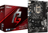
.... 6. Use the Floppy Configuration Utility to scroll through the list as all controllers may not be prompted Note with the Note necessary files. 4. Use the up and down arrow keys to create a floppy disk with a screen asking you need to Specify Additional Device. 3. Select 4: Exit and press Enter. 11. Setup will happen immediately after pressing F6. Press Enter. 5. Select the volume size and press Enter. 8. Install the RAID Driver Using the F6 Installation...
.... 6. Use the Floppy Configuration Utility to scroll through the list as all controllers may not be prompted Note with the Note necessary files. 4. Use the up and down arrow keys to create a floppy disk with a screen asking you need to Specify Additional Device. 3. Select 4: Exit and press Enter. 11. Setup will happen immediately after pressing F6. Press Enter. 5. Select the volume size and press Enter. 8. Install the RAID Driver Using the F6 Installation...

Intel Rapid Storage Guide
Page 16
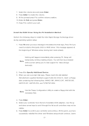
... can use the Floppy Configuration Utility to create a floppy disk with a screen asking you to load support for mass storage device(s). 2. Press F6 when you see a message in the status line that says, Press F6 if you see a prompt that says, Please insert the disk labeled Manufacturer-supplied hardware support disk into Drive A:, insert a floppy disk containing the following steps to install the Intel® Rapid Storage Technology driver using F6 when in AHCI/RAID mode...
... can use the Floppy Configuration Utility to create a floppy disk with a screen asking you to load support for mass storage device(s). 2. Press F6 when you see a message in the status line that says, Press F6 if you see a prompt that says, Please insert the disk labeled Manufacturer-supplied hardware support disk into Drive A:, insert a floppy disk containing the following steps to install the Intel® Rapid Storage Technology driver using F6 when in AHCI/RAID mode...

RAID Installation Guide
Page 7
... models A. STEP 4: Install Windows® 10 64-bit OS on how to set RAID configuration. Follow the onscreen instruction to enter BIOS setup utility. STEP 3: Set RAID configuration Please refer to install Windows® 10 64-bit OS on your SATA / SATA2 / SATA3 HDDs with just one simple click in UEFI setup. STEP 2: Use ASRock Easy RAID Installer Easy RAID Installer can copy the RAID driver from a support CD to confirm the selection C. Plug in the BIOS before setting your RAID configuration. Press [Enter] to your USB storage device with RAID...
... models A. STEP 4: Install Windows® 10 64-bit OS on how to set RAID configuration. Follow the onscreen instruction to enter BIOS setup utility. STEP 3: Set RAID configuration Please refer to install Windows® 10 64-bit OS on your SATA / SATA2 / SATA3 HDDs with just one simple click in UEFI setup. STEP 2: Use ASRock Easy RAID Installer Easy RAID Installer can copy the RAID driver from a support CD to confirm the selection C. Plug in the BIOS before setting your RAID configuration. Press [Enter] to your USB storage device with RAID...

RAID Installation Guide
Page 23
... the files into a USB flash disk or copy the files from ASRock's motherboard support CD. (Please copy the files under the following directory: 32 bit: ..\i386\Win7_Intel.. 64-bit: ..\AMD64\Win7-64_Intel.. Installing Windows® on a HDD larger than 2TB in RAID mode Windows® 10 does not support HDD's larger than 2TB. STEP 2: Install Windows® 10 64-bit OS Press to launch boot menu at system POST and choose the item "UEFI:" to use Windows®...
... the files into a USB flash disk or copy the files from ASRock's motherboard support CD. (Please copy the files under the following directory: 32 bit: ..\i386\Win7_Intel.. 64-bit: ..\AMD64\Win7-64_Intel.. Installing Windows® on a HDD larger than 2TB in RAID mode Windows® 10 does not support HDD's larger than 2TB. STEP 2: Install Windows® 10 64-bit OS Press to launch boot menu at system POST and choose the item "UEFI:" to use Windows®...

Quick Installation Guide
Page 4
...-pin DDR4 DIMM Slots (DDR4_A2, DDR4_B2) 7 ATX Power Connector (ATXPWR1) 8 USB 3.2 Gen1 Header (USB3_5_6) 9 SATA3 Connector (SATA3_1) 10 SATA3 Connector (SATA3_0) 11 SATA3 Connector (SATA3_2) 12 SATA3 Connector (SATA3_3) 13 Post Status Checker (PSC) 14 SPI TPM Header (SPI_TPM_J1) 15 System Panel Header (PANEL1) 16 SATA3 Connector (SATA3_4) 17 SATA3 Connector (SATA3_5) 18 Power LED and Speaker Header (SPK_PLED1) 19 Chassis/Water Pump Fan Connector (CHA_FAN3/WP) 20 Chassis/Water Pump Fan Connector (CHA_FAN1/WP) 21 Clear CMOS Jumper (CLRMOS1...
...-pin DDR4 DIMM Slots (DDR4_A2, DDR4_B2) 7 ATX Power Connector (ATXPWR1) 8 USB 3.2 Gen1 Header (USB3_5_6) 9 SATA3 Connector (SATA3_1) 10 SATA3 Connector (SATA3_0) 11 SATA3 Connector (SATA3_2) 12 SATA3 Connector (SATA3_3) 13 Post Status Checker (PSC) 14 SPI TPM Header (SPI_TPM_J1) 15 System Panel Header (PANEL1) 16 SATA3 Connector (SATA3_4) 17 SATA3 Connector (SATA3_5) 18 Power LED and Speaker Header (SPK_PLED1) 19 Chassis/Water Pump Fan Connector (CHA_FAN3/WP) 20 Chassis/Water Pump Fan Connector (CHA_FAN1/WP) 21 Clear CMOS Jumper (CLRMOS1...
Quick Installation Guide
Page 6
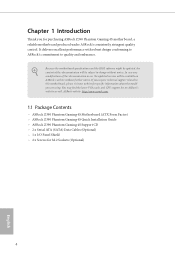
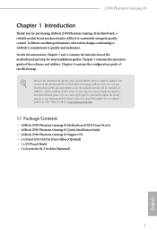
... Phantom Gaming 4S Motherboard (ATX Form Factor) • ASRock Z390 Phantom Gaming 4S Quick Installation Guide • ASRock Z390 Phantom Gaming 4S Support CD • 2 x Serial ATA (SATA) Data Cables (Optional) • 1 x I/O Panel Shield • 2 x Screws for specific information about the model you for purchasing ASRock Z390 Phantom Gaming 4S motherboard, a reliable motherboard produced under ASRock's consistently stringent quality control. In case any modifications of this documentation will be subject to quality and endurance. Chapter 1 Introduction Thank you are using...
... Phantom Gaming 4S Motherboard (ATX Form Factor) • ASRock Z390 Phantom Gaming 4S Quick Installation Guide • ASRock Z390 Phantom Gaming 4S Support CD • 2 x Serial ATA (SATA) Data Cables (Optional) • 1 x I/O Panel Shield • 2 x Screws for specific information about the model you for purchasing ASRock Z390 Phantom Gaming 4S motherboard, a reliable motherboard produced under ASRock's consistently stringent quality control. In case any modifications of this documentation will be subject to quality and endurance. Chapter 1 Introduction Thank you are using...

Quick Installation Guide
Page 7
... boot disks • 3 x PCI Express 3.0 x1 Slots (Flexible PCIe) • Supports AMD Quad CrossFireXTM and CrossFireXTM • 1 x M.2 Socket (Key E), supports type 2230 WiFi/BT module and Intel® CNVi (Integrated WiFi/BT) Graphics * Intel® UHD Graphics Built-in non- Z390 Phantom Gaming 4S 1.2 Specifications Platform • ATX Form Factor • Solid Capacitor design CPU • Supports 9th and 8th Gen Intel® CoreTM Processors (Socket 1151) • Digi Power design • 8 Power Phase design • Supports...
... boot disks • 3 x PCI Express 3.0 x1 Slots (Flexible PCIe) • Supports AMD Quad CrossFireXTM and CrossFireXTM • 1 x M.2 Socket (Key E), supports type 2230 WiFi/BT module and Intel® CNVi (Integrated WiFi/BT) Graphics * Intel® UHD Graphics Built-in non- Z390 Phantom Gaming 4S 1.2 Specifications Platform • ATX Form Factor • Solid Capacitor design CPU • Supports 9th and 8th Gen Intel® CoreTM Processors (Socket 1151) • Digi Power design • 8 Power Phase design • Supports...

Quick Installation Guide
Page 9
... Gaming 4S Storage • 6 x SATA3 6.0 Gb/s Connectors, support RAID (RAID 0, RAID 1, RAID 5, RAID 10, Intel Rapid Storage Technology 16), NCQ, AHCI and Hot Plug* * If M2_1 is occupied by a SATA-type M.2 device, SATA3_1 will be disabled. • 1 x Ultra M.2 Socket (M2_1), supports M Key type 2230/2242/2260/2280/22110 M.2 SATA3 6.0 Gb/s module and M.2 PCI Express module up to Gen3 x4 (32 Gb/s)** ** Supports Intel® OptaneTM Technology ** Supports NVMe SSD as boot disks ** Supports ASRock U.2 Kit Connector • 1 x COM Port Header • 1 x SPI TPM Header • 1 x Power LED...
... Gaming 4S Storage • 6 x SATA3 6.0 Gb/s Connectors, support RAID (RAID 0, RAID 1, RAID 5, RAID 10, Intel Rapid Storage Technology 16), NCQ, AHCI and Hot Plug* * If M2_1 is occupied by a SATA-type M.2 device, SATA3_1 will be disabled. • 1 x Ultra M.2 Socket (M2_1), supports M Key type 2230/2242/2260/2280/22110 M.2 SATA3 6.0 Gb/s module and M.2 PCI Express module up to Gen3 x4 (32 Gb/s)** ** Supports Intel® OptaneTM Technology ** Supports NVMe SSD as boot disks ** Supports ASRock U.2 Kit Connector • 1 x COM Port Header • 1 x SPI TPM Header • 1 x Power LED...
User Manual
Page 8
... Installation Guide • ASRock Z390 Phantom Gaming 4S Support CD • 2 x Serial ATA (SATA) Data Cables (Optional) • 1 x I/O Panel Shield • 2 x Screws for purchasing ASRock Z390 Phantom Gaming 4S motherboard, a reliable motherboard produced under ASRock's consistently stringent quality control. You may find the latest VGA cards and CPU support list on ASRock's website without notice. In case any modifications of this documentation, Chapter 1 and 2 contains the introduction of this motherboard, please visit our website for specific information about the model...
... Installation Guide • ASRock Z390 Phantom Gaming 4S Support CD • 2 x Serial ATA (SATA) Data Cables (Optional) • 1 x I/O Panel Shield • 2 x Screws for purchasing ASRock Z390 Phantom Gaming 4S motherboard, a reliable motherboard produced under ASRock's consistently stringent quality control. You may find the latest VGA cards and CPU support list on ASRock's website without notice. In case any modifications of this documentation, Chapter 1 and 2 contains the introduction of this motherboard, please visit our website for specific information about the model...

User Manual
Page 11
.../s Connectors, support RAID (RAID 0, RAID 1, RAID 5, RAID 10, Intel Rapid Storage Technology 16), NCQ, AHCI and Hot Plug* * If M2_1 is occupied by a SATA-type M.2 device, SATA3_1 will be disabled. • 1 x Ultra M.2 Socket (M2_1), supports M Key type 2230/2242/2260/2280/22110 M.2 SATA3 6.0 Gb/s module and M.2 PCI Express module up to Gen3 x4 (32 Gb/s)** ** Supports Intel® OptaneTM Technology ** Supports NVMe SSD as boot disks ** Supports ASRock U.2 Kit Connector • 1 x COM Port Header • 1 x SPI TPM Header • 1 x Power LED and Speaker Header • 2 x RGB LED Headers...
.../s Connectors, support RAID (RAID 0, RAID 1, RAID 5, RAID 10, Intel Rapid Storage Technology 16), NCQ, AHCI and Hot Plug* * If M2_1 is occupied by a SATA-type M.2 device, SATA3_1 will be disabled. • 1 x Ultra M.2 Socket (M2_1), supports M Key type 2230/2242/2260/2280/22110 M.2 SATA3 6.0 Gb/s module and M.2 PCI Express module up to Gen3 x4 (32 Gb/s)** ** Supports Intel® OptaneTM Technology ** Supports NVMe SSD as boot disks ** Supports ASRock U.2 Kit Connector • 1 x COM Port Header • 1 x SPI TPM Header • 1 x Power LED and Speaker Header • 2 x RGB LED Headers...

User Manual
Page 14
...-pin DDR4 DIMM Slots (DDR4_A2, DDR4_B2) 7 ATX Power Connector (ATXPWR1) 8 USB 3.2 Gen1 Header (USB3_5_6) 9 SATA3 Connector (SATA3_1) 10 SATA3 Connector (SATA3_0) 11 SATA3 Connector (SATA3_2) 12 SATA3 Connector (SATA3_3) 13 Post Status Checker (PSC) 14 SPI TPM Header (SPI_TPM_J1) 15 System Panel Header (PANEL1) 16 SATA3 Connector (SATA3_4) 17 SATA3 Connector (SATA3_5) 18 Power LED and Speaker Header (SPK_PLED1) 19 Chassis/Water Pump Fan Connector (CHA_FAN3/WP) 20 Chassis/Water Pump Fan Connector (CHA_FAN1/WP) 21 Clear CMOS Jumper (CLRMOS1...
...-pin DDR4 DIMM Slots (DDR4_A2, DDR4_B2) 7 ATX Power Connector (ATXPWR1) 8 USB 3.2 Gen1 Header (USB3_5_6) 9 SATA3 Connector (SATA3_1) 10 SATA3 Connector (SATA3_0) 11 SATA3 Connector (SATA3_2) 12 SATA3 Connector (SATA3_3) 13 Post Status Checker (PSC) 14 SPI TPM Header (SPI_TPM_J1) 15 System Panel Header (PANEL1) 16 SATA3 Connector (SATA3_4) 17 SATA3 Connector (SATA3_5) 18 Power LED and Speaker Header (SPK_PLED1) 19 Chassis/Water Pump Fan Connector (CHA_FAN3/WP) 20 Chassis/Water Pump Fan Connector (CHA_FAN1/WP) 21 Clear CMOS Jumper (CLRMOS1...

User Manual
Page 31
... three identical PCI Express x16 graphics cards. 1. It is provided with the graphics card you pair a 12-pipe CrossFireXTM Edition card with this motherboard. Please refer to enable CrossFireXTM. Download the drivers from the AMD's website: www.amd.com 3. If you purchase, not bundled with a 16-pipe card, both cards will operate as 12-pipe cards while in CrossFireXTM mode. 5. CrossFire Bridge Step 2 Connect two graphics cards by installing a CrossFire Bridge...
... three identical PCI Express x16 graphics cards. 1. It is provided with the graphics card you pair a 12-pipe CrossFireXTM Edition card with this motherboard. Please refer to enable CrossFireXTM. Download the drivers from the AMD's website: www.amd.com 3. If you purchase, not bundled with a 16-pipe card, both cards will operate as 12-pipe cards while in CrossFireXTM mode. 5. CrossFire Bridge Step 2 Connect two graphics cards by installing a CrossFire Bridge...

User Manual
Page 33
... optional download. English 26 Select the GPU number according to your computer. Step 2 Remove the AMD drivers if you have any previously installed Catalyst drivers prior to uninstall any VGA drivers installed in the Windows® system tray. We recommend using this utility to installation. Step 3 Install the required drivers and CATALYST Control Center then restart your graphics card and click Apply. Then select Enable AMD CrossFireX and click Apply. 2.8.2 Driver Installation and Setup...
... optional download. English 26 Select the GPU number according to your computer. Step 2 Remove the AMD drivers if you have any previously installed Catalyst drivers prior to uninstall any VGA drivers installed in the Windows® system tray. We recommend using this utility to installation. Step 3 Install the required drivers and CATALYST Control Center then restart your graphics card and click Apply. Then select Enable AMD CrossFireX and click Apply. 2.8.2 Driver Installation and Setup...

User Manual
Page 41
... motherboard contains necessary drivers and useful utilities that the motherboard supports. The CD automatically displays the Main Menu if "AUTORUN" is enabled in the Support CD to install it. 34 English Click on a specific item then follow the order from top to bottom to your system will be auto-detected and listed on the file "ASRSETUP.EXE" in your CD-ROM drive. If the Main Menu does not appear automatically, locate...
... motherboard contains necessary drivers and useful utilities that the motherboard supports. The CD automatically displays the Main Menu if "AUTORUN" is enabled in the Support CD to install it. 34 English Click on a specific item then follow the order from top to bottom to your system will be auto-detected and listed on the file "ASRSETUP.EXE" in your CD-ROM drive. If the Main Menu does not appear automatically, locate...
User Manual
Page 68
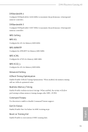
... 3 (1867 MHz) to maximize the performance of intergrated memory controller. When enabled, the memory timing will allow performing realtime memory timing changes after MRC_DONE. Exit On Failure Enable/Disable Exit On Failure for Memory MRS MR2. Reset on Training Fail Enable/Disable to enable or disable Command Tristate support. MRS tCWL Configure the tCWL for MRC training steps. Z390 Phantom Gaming 4S Dll Bandwidth 2 Configure Dll Bandwidth 2 (1600 MHz) to maximize the performance...
... 3 (1867 MHz) to maximize the performance of intergrated memory controller. When enabled, the memory timing will allow performing realtime memory timing changes after MRC_DONE. Exit On Failure Enable/Disable Exit On Failure for Memory MRS MR2. Reset on Training Fail Enable/Disable to enable or disable Command Tristate support. MRS tCWL Configure the tCWL for MRC training steps. Z390 Phantom Gaming 4S Dll Bandwidth 2 Configure Dll Bandwidth 2 (1600 MHz) to maximize the performance...

User Manual
Page 75
... Support This option enables/disables the control of ASPM on CPU side of memory that is allocated to enable onboard HD audio and automatically disable it when a sound card is installed. IGPU Multi-Monitor Select disable to keep the integrated graphics enabled at all CPU downstream devices. Set to Auto to the integrated graphics processor when the system boots up. PCIE5 Link Speed Select the link speed for PCIE3. Share Memory Configure the size of the DMI Link. PCIE ASPM Support This option enables/disables...
... Support This option enables/disables the control of ASPM on CPU side of memory that is allocated to enable onboard HD audio and automatically disable it when a sound card is installed. IGPU Multi-Monitor Select disable to keep the integrated graphics enabled at all CPU downstream devices. Set to Auto to the integrated graphics processor when the system boots up. PCIE5 Link Speed Select the link speed for PCIE3. Share Memory Configure the size of the DMI Link. PCIE ASPM Support This option enables/disables...

User Manual
Page 78
... Z390 Phantom Gaming 4S Discrete Thunderbolt(TM) Support Enable or disable the Discrete Thunderbolt(TM) Support. Titan Ridge Workaround for OSUP Enable or disable Titan Ridge Workaround for the Thunderbolt ports. ACPI Notify on TBT hot-plug When enbled, BIOS generates software SMI to assign resource to allow booting from Usb devices which are present behind Thunderbolt. Thunderbolt Usb Support Enabled to TBT devices. SW SMI on TBT Hot-plug When enbled, BIOS generates ACPI...
... Z390 Phantom Gaming 4S Discrete Thunderbolt(TM) Support Enable or disable the Discrete Thunderbolt(TM) Support. Titan Ridge Workaround for OSUP Enable or disable Titan Ridge Workaround for the Thunderbolt ports. ACPI Notify on TBT hot-plug When enbled, BIOS generates software SMI to assign resource to allow booting from Usb devices which are present behind Thunderbolt. Thunderbolt Usb Support Enabled to TBT devices. SW SMI on TBT Hot-plug When enbled, BIOS generates ACPI...
User Manual
Page 86
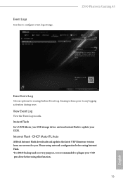
... Flash - DHCP (Auto IP), Auto ASRock Internet Flash downloads and updates the latest UEFI firmware version from our servers for erasing Smbios Event Log. View Event Log View the Event Log records. Please setup network configuration before using this to any logging activation during reset. Z390 Phantom Gaming 4S Erase Event Log Choose options for you. Erasing is recommended to plug in your USB storage device and run Instant Flash to update your USB pen drive before using Internet Flash...
... Flash - DHCP (Auto IP), Auto ASRock Internet Flash downloads and updates the latest UEFI firmware version from our servers for erasing Smbios Event Log. View Event Log View the Event Log records. Please setup network configuration before using this to any logging activation during reset. Z390 Phantom Gaming 4S Erase Event Log Choose options for you. Erasing is recommended to plug in your USB storage device and run Instant Flash to update your USB pen drive before using Internet Flash...

User Manual
Page 87
Internet Setting Enable or disable sound effects in the setup utility. UEFI Download Server Select a server to configure internet connection settings for Internet Flash. Network Configuration Use this to download the UEFI firmware. 80 English
Internet Setting Enable or disable sound effects in the setup utility. UEFI Download Server Select a server to configure internet connection settings for Internet Flash. Network Configuration Use this to download the UEFI firmware. 80 English

User Manual
Page 91
... password. Intel(R) Platform Trust Technology Enable/disable Intel PTT in the UEFI Setup Utility. Supervisor Password Set or change the settings in the UEFI Setup Utility. Secure Boot Use this section you may also clear the user password. Leave it blank and press enter to remove the password. You may set or change the supervisor/user password for the system. 4.9 Security Screen In this item to enable or disable support for Secure Boot. Disable this option to change the password for the user account. User Password Set or change the settings...
... password. Intel(R) Platform Trust Technology Enable/disable Intel PTT in the UEFI Setup Utility. Supervisor Password Set or change the settings in the UEFI Setup Utility. Secure Boot Use this section you may also clear the user password. Leave it blank and press enter to remove the password. You may set or change the supervisor/user password for the system. 4.9 Security Screen In this item to enable or disable support for Secure Boot. Disable this option to change the password for the user account. User Password Set or change the settings...


