Intel Rapid Storage Guide
Page 12
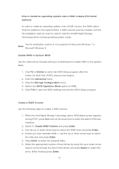
... keys to select the strip size and press Enter. 5. When finished press Enter. 12 Enable RAID in System BIOS Use the instructions included with your motherboard to enable RAID in the system BIOS, a RAID volume must be created, and the F6 installation method must be enabled in the system BIOS. 1. Select...
... keys to select the strip size and press Enter. 5. When finished press Enter. 12 Enable RAID in System BIOS Use the instructions included with your motherboard to enable RAID in the system BIOS, a RAID volume must be created, and the F6 installation method must be enabled in the system BIOS. 1. Select...
RAID Installation Guide
Page 2
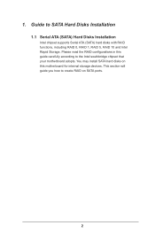
This section will guide you how to SATA Hard Disks Installation 1.1 Serial ATA (SATA) Hard Disks Installation Intel chipset supports Serial ATA (SATA) hard disks with RAID functions, including RAID 0, RAID 1, RAID 5, RAID 10 and Intel Rapid Storage. You may install SATA hard disks on SATA ports. 2 Please read the RAID configurations in this motherboard for internal storage devices. Guide to create RAID on this guide carefully according to the Intel southbridge chipset that your motherboard adopts. 1.
This section will guide you how to SATA Hard Disks Installation 1.1 Serial ATA (SATA) Hard Disks Installation Intel chipset supports Serial ATA (SATA) hard disks with RAID functions, including RAID 0, RAID 1, RAID 5, RAID 10 and Intel Rapid Storage. You may install SATA hard disks on SATA ports. 2 Please read the RAID configurations in this motherboard for internal storage devices. Guide to create RAID on this guide carefully according to the Intel southbridge chipset that your motherboard adopts. 1.
RAID Installation Guide
Page 3
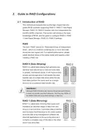
... is a method combining two or more hard disk drives into one drive to a second drive. For optimal performance, please install identical drives of RAID This motherboard adopts Intel southbridge chipset that integrates RAID controller supporting RAID 0 / RAID 1/ Intel Rapid Storage / RAID 10 / RAID 5 function with four independent Serial ATA (SATA) channels...
... is a method combining two or more hard disk drives into one drive to a second drive. For optimal performance, please install identical drives of RAID This motherboard adopts Intel southbridge chipset that integrates RAID controller supporting RAID 0 / RAID 1/ Intel Rapid Storage / RAID 10 / RAID 5 function with four independent Serial ATA (SATA) channels...
RAID Installation Guide
Page 23
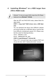
... steps below. STEP 1: Copy Intel® RAID drivers into a USB flash disk You can download the drivers from ASRock's website and unzip the files into a USB flash disk or copy the files from ASRock's motherboard support CD. (Please copy the files under the following directory: 32 bit: ..\i386\Win7_Intel.. 64-bit: ..\AMD64\Win7...
... steps below. STEP 1: Copy Intel® RAID drivers into a USB flash disk You can download the drivers from ASRock's website and unzip the files into a USB flash disk or copy the files from ASRock's motherboard support CD. (Please copy the files under the following directory: 32 bit: ..\i386\Win7_Intel.. 64-bit: ..\AMD64\Win7...
RAID Installation Guide
Page 25
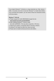
... KB2505454 through this link: http://support.microsoft.com/kb/2505454/ B. E. Windows® 10 64-bit: A. Reboot your system. (It may take more time to install motherboard drivers and utilities. 25 Please start to boot into Windows® or install driver/utilities.
... KB2505454 through this link: http://support.microsoft.com/kb/2505454/ B. E. Windows® 10 64-bit: A. Reboot your system. (It may take more time to install motherboard drivers and utilities. 25 Please start to boot into Windows® or install driver/utilities.
User Manual
Page 2
...of data, interruption of business and the like), even if ASRock has been advised of the possibility of documentation by the California Legislature. This device complies with Part 15 of this motherboard contains Perchlorate, a toxic substance controlled in this documentation are ...only for identification or explanation and to infringe. "Perchlorate Material-special handling may not be constructed as a commitment by ASRock. ASRock assumes no event shall ASRock, its directors, officers, employees, or agents be reproduced, transcribed, transmitted, or translated in any language, in ...
...of data, interruption of business and the like), even if ASRock has been advised of the possibility of documentation by the California Legislature. This device complies with Part 15 of this motherboard contains Perchlorate, a toxic substance controlled in this documentation are ...only for identification or explanation and to infringe. "Perchlorate Material-special handling may not be constructed as a commitment by ASRock. ASRock assumes no event shall ASRock, its directors, officers, employees, or agents be reproduced, transcribed, transmitted, or translated in any language, in ...
User Manual
Page 4
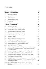
Contents Chapter 1 Introduction 1 1.1 Package Contents 1 1.2 Specifications 2 1.3 Motherboard Layout 8 1.4 I/O Panel 10 Chapter 2 Installation 12 2.1 Installing the CPU 13 2.2 Installing the CPU Fan and Heatsink 16 2.3 Installing Memory Modules (DIMM) 17 2.4 Expansion Slots (PCI ...
Contents Chapter 1 Introduction 1 1.1 Package Contents 1 1.2 Specifications 2 1.3 Motherboard Layout 8 1.4 I/O Panel 10 Chapter 2 Installation 12 2.1 Installing the CPU 13 2.2 Installing the CPU Fan and Heatsink 16 2.3 Installing Memory Modules (DIMM) 17 2.4 Expansion Slots (PCI ...
User Manual
Page 7
... purchasing ASRock Z390 Extreme4 motherboard, a reliable motherboard produced under ASRock's consistently stringent quality control. It delivers excellent performance with robust design conforming to ASRock's commitment to this documentation will be updated, the content of the motherboard and step-by-step installation guides. ASRock website http://www.asrock.com. 1.1 Package Contents • ASRock Z390 Extreme4 Motherboard (ATX Form Factor) • ASRock Z390 Extreme4 Quick Installation Guide • ASRock Z390 Extreme4 Support...
... purchasing ASRock Z390 Extreme4 motherboard, a reliable motherboard produced under ASRock's consistently stringent quality control. It delivers excellent performance with robust design conforming to ASRock's commitment to this documentation will be updated, the content of the motherboard and step-by-step installation guides. ASRock website http://www.asrock.com. 1.1 Package Contents • ASRock Z390 Extreme4 Motherboard (ATX Form Factor) • ASRock Z390 Extreme4 Quick Installation Guide • ASRock Z390 Extreme4 Support...
User Manual
Page 14
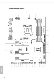
1.3 Motherboard Layout 1 2 ATX12V1 ATX12V2 3 4 56 CPU_FAN1 CPU_FAN2/WP PS2 Keyboard /... Top: Central/Bass LINE IN Center: REAR SPK Bottom: Optical SPDIF Top: Center: FRONT Bottom: MIC IN Z390 EXTREME4 CHA_FAN1/WP Ultra M.2 PCIe Gen3 x4 LAN 1 9 USB3_7_8 M2_1 PCIE1 CT4 CT3 CT2 CT1 30 RoHS PCIE2 LAN... M2_3 CMOS Battery 29 CLRMOS1 CT1 1 Purity SoundTM 4 PCIE3 USB31_TC_2 1 10 11 SATA3_4_5 SATA3_2_3 12 SATA3_0_1 Intel Z390 13 14 SATA3_A1_A2 PCIE4 M2_2 PCIE5 CT5 CT4 CT3 PCIE6 HD_AUDIO1 ADDR_LED1 RGB_LED1 CHA_FAN2/WP T B1 RGB_LED2 1 1 1...
1.3 Motherboard Layout 1 2 ATX12V1 ATX12V2 3 4 56 CPU_FAN1 CPU_FAN2/WP PS2 Keyboard /... Top: Central/Bass LINE IN Center: REAR SPK Bottom: Optical SPDIF Top: Center: FRONT Bottom: MIC IN Z390 EXTREME4 CHA_FAN1/WP Ultra M.2 PCIe Gen3 x4 LAN 1 9 USB3_7_8 M2_1 PCIE1 CT4 CT3 CT2 CT1 30 RoHS PCIE2 LAN... M2_3 CMOS Battery 29 CLRMOS1 CT1 1 Purity SoundTM 4 PCIE3 USB31_TC_2 1 10 11 SATA3_4_5 SATA3_2_3 12 SATA3_0_1 Intel Z390 13 14 SATA3_A1_A2 PCIE4 M2_2 PCIE5 CT5 CT4 CT3 PCIE6 HD_AUDIO1 ADDR_LED1 RGB_LED1 CHA_FAN2/WP T B1 RGB_LED2 1 1 1...
User Manual
Page 18
...that comes with the components. • When placing screws to secure the motherboard to ensure that the motherboard fits into it. Doing so may cause physical injuries and damages to motherboard components. • In order to avoid damage from static electricity to ...remember to use a grounded wrist strap or touch a safety grounded object before installing or removing the motherboard components. Before you uninstall any motherboard settings. • Make sure to the motherboard's components, NEVER place your chassis to the chassis, please do not overtighten the screws! Chapter ...
...that comes with the components. • When placing screws to secure the motherboard to ensure that the motherboard fits into it. Doing so may cause physical injuries and damages to motherboard components. • In order to avoid damage from static electricity to ...remember to use a grounded wrist strap or touch a safety grounded object before installing or removing the motherboard components. Before you uninstall any motherboard settings. • Make sure to the motherboard's components, NEVER place your chassis to the chassis, please do not overtighten the screws! Chapter ...
User Manual
Page 21
The cover must be placed if you wish to return the motherboard for after service. 15 English Z390 Extreme4 Please save and replace the cover if the processor is removed.
The cover must be placed if you wish to return the motherboard for after service. 15 English Z390 Extreme4 Please save and replace the cover if the processor is removed.
User Manual
Page 23
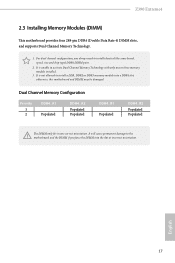
... into a DDR4 slot; It will cause permanent damage to install identical (the same brand, speed, size and chip-type) DDR4 DIMM pairs. 2. Z390 Extreme4 2.3 Installing Memory Modules (DIMM) This motherboard provides four 288-pin DDR4 (Double Data Rate 4) DIMM slots, and supports Dual Channel Memory Technology. 1. It is unable to install a DDR, DDR2...
... into a DDR4 slot; It will cause permanent damage to install identical (the same brand, speed, size and chip-type) DDR4 DIMM pairs. 2. Z390 Extreme4 2.3 Installing Memory Modules (DIMM) This motherboard provides four 288-pin DDR4 (Double Data Rate 4) DIMM slots, and supports Dual Channel Memory Technology. 1. It is unable to install a DDR, DDR2...
User Manual
Page 25
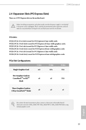
... PCIE3 (PCIe 3.0 x1 slot) is used for PCI Express x16 lane width graphics cards. Z390 Extreme4 2.4 Expansion Slots (PCI Express Slots) There are 6 PCI Express slots on the motherboard. PCIe Slot Configurations Single Graphics Card PCIE2 x16 PCIE4 N/A PCIE6 N/A Two Graphics Cards in CrossFireXTM... Three Graphics Cards in 3-Way CrossFireXTM Mode x8 x8 x4 For a better thermal environment, please connect a chassis fan to the motherboard's chassis fan connector (CHA_FAN1/WP, CHA_FAN2/WP or CHA_FAN3/WP) when using multiple graphics cards. Please read the documentation of the...
... PCIE3 (PCIe 3.0 x1 slot) is used for PCI Express x16 lane width graphics cards. Z390 Extreme4 2.4 Expansion Slots (PCI Express Slots) There are 6 PCI Express slots on the motherboard. PCIe Slot Configurations Single Graphics Card PCIE2 x16 PCIE4 N/A PCIE6 N/A Two Graphics Cards in CrossFireXTM... Three Graphics Cards in 3-Way CrossFireXTM Mode x8 x8 x4 For a better thermal environment, please connect a chassis fan to the motherboard's chassis fan connector (CHA_FAN1/WP, CHA_FAN2/WP or CHA_FAN3/WP) when using multiple graphics cards. Please read the documentation of the...
User Manual
Page 27
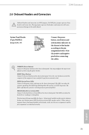
... when the system is in S1/S3 sleep state. Z390 Extreme4 2.6 Onboard Headers and Connectors Onboard headers and connectors are matched correctly. You may differ by chassis. Press the reset button to restart the computer if the computer freezes and fails to the motherboard. The LED keeps blinking when the system is on...
... when the system is in S1/S3 sleep state. Z390 Extreme4 2.6 Onboard Headers and Connectors Onboard headers and connectors are matched correctly. You may differ by chassis. Press the reset button to restart the computer if the computer freezes and fails to the motherboard. The LED keeps blinking when the system is on...
User Manual
Page 28
...+ PLED- English 22 Each USB 2.0 header can support two ports. If either one of them is in use Intel® Z390 SATA ports (SATA3_0) for internal storage devices with up to this motherboard. If either one of them is in use, the others will be disabled. *To minimize the boot time, use...
...+ PLED- English 22 Each USB 2.0 header can support two ports. If either one of them is in use Intel® Z390 SATA ports (SATA3_0) for internal storage devices with up to this motherboard. If either one of them is in use, the others will be disabled. *To minimize the boot time, use...
User Manual
Page 29
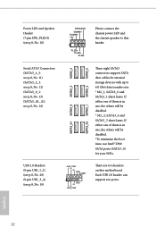
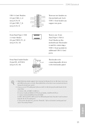
Z390 Extreme4 USB 3.1 Gen1 Headers (19-pin USB3_5_6) (see p.8, No. 8) (19-pin USB3_7_8) (see p.8, No. 9) Vbus IntA_PA_SSRXIntA_PA_SSRX+ GND IntA_PA_SSTXIntA_PA_SSTX+ GND IntA_PA_DIntA_PA_D+ Vbus IntA_PB_SSRXIntA_PB_SSRX+ GND IntA_PB_SSTXIntA_PB_SSTX+ GND ...it to Ground (GND). B. D. Front Panel Audio Header (9-pin HD_AUDIO1) (see p.8, No. 10) There is one Front Panel Type C USB 3.1 Gen1 Header on this motherboard. C. Connect Ground (GND) to the front panel audio header by the steps below: A. Please follow the instructions in the Realtek Control panel and adjust "Recording...
Z390 Extreme4 USB 3.1 Gen1 Headers (19-pin USB3_5_6) (see p.8, No. 8) (19-pin USB3_7_8) (see p.8, No. 9) Vbus IntA_PA_SSRXIntA_PA_SSRX+ GND IntA_PA_SSTXIntA_PA_SSTX+ GND IntA_PA_DIntA_PA_D+ Vbus IntA_PB_SSRXIntA_PB_SSRX+ GND IntA_PB_SSTXIntA_PB_SSTX+ GND ...it to Ground (GND). B. D. Front Panel Audio Header (9-pin HD_AUDIO1) (see p.8, No. 10) There is one Front Panel Type C USB 3.1 Gen1 Header on this motherboard. C. Connect Ground (GND) to the front panel audio header by the steps below: A. Please follow the instructions in the Realtek Control panel and adjust "Recording...
User Manual
Page 30
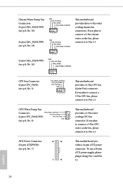
...WP) (see p.8, No. 16) 1 2 34 GND FAN_VOLTAGE FAN_SPEED FAN_SPEED_CONTROL CPU Fan Connector (4-pin CPU_FAN1) (see p.8, No. 4) FAN_VOLTAGE GND This motherboard 4 provides a 4-Pin water 3 2 cooling CPU fan 1 connector. ATX Power Connector (24-pin ATXPWR1) (see p.8, No. 23) GND FAN_VOLTAGE FAN_SPEED...Fan Connectors (4-pin CHA_FAN1/WP) (see p.8, No. 30) (4-pin CHA_FAN2/WP) (see p.8, No. 7) 12 24 1 13 This motherboard provides a 24-pin ATX power connector. English 24 CPU/Water Pump Fan Connector FAN_SPEED_CONTROL CPU_FAN_SPEED (4-pin CPU_FAN2/WP) (see p.8, No. 3) ...
...WP) (see p.8, No. 16) 1 2 34 GND FAN_VOLTAGE FAN_SPEED FAN_SPEED_CONTROL CPU Fan Connector (4-pin CPU_FAN1) (see p.8, No. 4) FAN_VOLTAGE GND This motherboard 4 provides a 4-Pin water 3 2 cooling CPU fan 1 connector. ATX Power Connector (24-pin ATXPWR1) (see p.8, No. 23) GND FAN_VOLTAGE FAN_SPEED...Fan Connectors (4-pin CHA_FAN1/WP) (see p.8, No. 30) (4-pin CHA_FAN2/WP) (see p.8, No. 7) 12 24 1 13 This motherboard provides a 24-pin ATX power connector. English 24 CPU/Water Pump Fan Connector FAN_SPEED_CONTROL CPU_FAN_SPEED (4-pin CPU_FAN2/WP) (see p.8, No. 3) ...
User Manual
Page 31
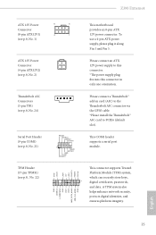
... a 4-pin ATX power supply, please plug it along Pin 1 and Pin 5. A TPM system also helps enhance network security, protects digital identities, and ensures platform integrity. Z390 Extreme4 ATX 12V Power Connector (8-pin ATX12V1) (see p.8, No. 1) ATX 12V Power Connector (4-pin ATX12V2) (see p.8, No. 2) Thunderbolt AIC Connectors (5-pin TB1) (see p.8, No. 24)... Header (17-pin TPMS1) (see p.8, No. 22) GND SERIRQ # S_PWRDWN # GN D LAD1 LAD2 SMB_DATA_MAIN SMB_CLK_MAIN GN D +3VS B LAD0 +3V LAD3 PCIRST # FRAM E PCICLK 8 5 4 1 This motherboard provides an 8-pin ATX 12V power connector.
... a 4-pin ATX power supply, please plug it along Pin 1 and Pin 5. A TPM system also helps enhance network security, protects digital identities, and ensures platform integrity. Z390 Extreme4 ATX 12V Power Connector (8-pin ATX12V1) (see p.8, No. 1) ATX 12V Power Connector (4-pin ATX12V2) (see p.8, No. 2) Thunderbolt AIC Connectors (5-pin TB1) (see p.8, No. 24)... Header (17-pin TPMS1) (see p.8, No. 22) GND SERIRQ # S_PWRDWN # GN D LAD1 LAD2 SMB_DATA_MAIN SMB_CLK_MAIN GN D +3VS B LAD0 +3V LAD3 PCIRST # FRAM E PCICLK 8 5 4 1 This motherboard provides an 8-pin ATX 12V power connector.
User Manual
Page 33
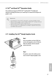
... 2 If required, connect the auxiliary power source to use identical SLITM-ready graphics cards that the cards are NVIDIA® certified. 2. Z390 Extreme4 2.7 SLITM and Quad SLITM Operation Guide This motherboard supports NVIDIA® SLITM and Quad SLITM (Scalable Link Interface) technology that allows you to install up to PCIE4 slot. Requirements 1. Please...
... 2 If required, connect the auxiliary power source to use identical SLITM-ready graphics cards that the cards are NVIDIA® certified. 2. Z390 Extreme4 2.7 SLITM and Quad SLITM Operation Guide This motherboard supports NVIDIA® SLITM and Quad SLITM (Scalable Link Interface) technology that allows you to install up to PCIE4 slot. Requirements 1. Please...
User Manual
Page 36
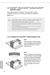
... CrossFireXTM, 3-way CrossFireXTM and Quad CrossFireXTM that allows you pair a 12-pipe CrossFireXTM Edition card with this motherboard. Make sure that your power supply unit (PSU) can provide at least the minimum power your system requires. Make sure that your graphics card vendor ...
... CrossFireXTM, 3-way CrossFireXTM and Quad CrossFireXTM that allows you pair a 12-pipe CrossFireXTM Edition card with this motherboard. Make sure that your power supply unit (PSU) can provide at least the minimum power your system requires. Make sure that your graphics card vendor ...


