

User Manual
Page 2
... or itness for loss of proits, loss of business, loss of data, interruption of business and the like), even if ASRock has been advised of the possibility of such damages arising from any indirect, special, incidental, or consequential damages (including damages for... infringe. CALIFORNIA, USA ONLY he Lithium battery adopted on this motherboard contains Perchlorate, a toxic substance controlled in this documentation may apply, see www.dtsc.ca.gov/hazardouswaste/ perchlorate" ASRock Website: http://www.asrock.com Copyright Notice: No part of this documentation are used only...
... or itness for loss of proits, loss of business, loss of data, interruption of business and the like), even if ASRock has been advised of the possibility of such damages arising from any indirect, special, incidental, or consequential damages (including damages for... infringe. CALIFORNIA, USA ONLY he Lithium battery adopted on this motherboard contains Perchlorate, a toxic substance controlled in this documentation may apply, see www.dtsc.ca.gov/hazardouswaste/ perchlorate" ASRock Website: http://www.asrock.com Copyright Notice: No part of this documentation are used only...
User Manual
Page 4
Contents Chapter 1 Introduction 1 1.1 Package Contents 1 1.2 Speciications 2 1.3 Motherboard Layout 6 1.4 I/O Panel 8 Chapter 2 Installation 10 2.1 Installing the CPU 11 2.2 Installing the CPU Fan and Heatsink 14 2.3 Installing Memory Modules (DIMM) 15 2.4 Expansion Slots (PCI Express ... Operation Guide 23 2.7.2 Driver Installation and Setup 25 2.8 M.2_SSD (NGFF) Module Installation Guide 26 Chapter 3 Software and Utilities Operation 29 3.1 Installing Drivers 29 3.2 A-Tuning 30 3.3 ASRock Live Update & APP Shop 34 3.3.1 UI Overview 34 3.3.2 Apps 35
Contents Chapter 1 Introduction 1 1.1 Package Contents 1 1.2 Speciications 2 1.3 Motherboard Layout 6 1.4 I/O Panel 8 Chapter 2 Installation 10 2.1 Installing the CPU 11 2.2 Installing the CPU Fan and Heatsink 14 2.3 Installing Memory Modules (DIMM) 15 2.4 Expansion Slots (PCI Express ... Operation Guide 23 2.7.2 Driver Installation and Setup 25 2.8 M.2_SSD (NGFF) Module Installation Guide 26 Chapter 3 Software and Utilities Operation 29 3.1 Installing Drivers 29 3.2 A-Tuning 30 3.3 ASRock Live Update & APP Shop 34 3.3.1 UI Overview 34 3.3.2 Apps 35
User Manual
Page 6
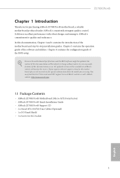
... updated, the content of the motherboard and step-by-step installation guides. ASRock website http://www.asrock.com. 1.1 Package Contents • ASRock Z170M Pro4S Motherboard (Micro ATX Form Factor) • ASRock Z170M Pro4S Quick Installation Guide • ASRock Z170M Pro4S Support CD • 2 x Serial ATA (SATA) Data Cables (Optional) • 1 x I/O Panel Shield • 1 x Screw for purchasing ASRock Z170M Pro4S motherboard, a reliable motherboard produced under ASRock's consistently stringent quality control...
... updated, the content of the motherboard and step-by-step installation guides. ASRock website http://www.asrock.com. 1.1 Package Contents • ASRock Z170M Pro4S Motherboard (Micro ATX Form Factor) • ASRock Z170M Pro4S Quick Installation Guide • ASRock Z170M Pro4S Support CD • 2 x Serial ATA (SATA) Data Cables (Optional) • 1 x I/O Panel Shield • 1 x Screw for purchasing ASRock Z170M Pro4S motherboard, a reliable motherboard produced under ASRock's consistently stringent quality control...

User Manual
Page 11
1.3 Motherboard Layout 1 2 34 ATX12V1 CPU_FAN1 PS2 Keyboard /Mouse USB 3.0 T: USB1 B: USB2 DVI1 ATXPWR1 DDR4_B2 (64 bit, 288-pin module) Front USB 3.0 DDR4_B1 (64 bit, 288-pin ...-pin module) DDR4_A1 (64 bit, 288-pin module) HDMI1 5 USB 3.0 T: USB7 B: USB8 USB 3.0 T: USB3 B: USB4 Top: RJ-45 6 SATA3_0 USB3_5_6 SATA3_1 21 CHA_FAN1 CMOS Battery 7 Z170M Pro4S Top: LINE IN Center: FRONT Bottom: MIC IN PCIE1 PCI Express 3.0 PCIE2 CT3 CT2 CT1 PCIE3 RoHS Super I/O M2_1 Intel Z170 SATA3_2 SATA3_3 8 CHA_FAN2 9 10...
1.3 Motherboard Layout 1 2 34 ATX12V1 CPU_FAN1 PS2 Keyboard /Mouse USB 3.0 T: USB1 B: USB2 DVI1 ATXPWR1 DDR4_B2 (64 bit, 288-pin module) Front USB 3.0 DDR4_B1 (64 bit, 288-pin ...-pin module) DDR4_A1 (64 bit, 288-pin module) HDMI1 5 USB 3.0 T: USB7 B: USB8 USB 3.0 T: USB3 B: USB4 Top: RJ-45 6 SATA3_0 USB3_5_6 SATA3_1 21 CHA_FAN1 CMOS Battery 7 Z170M Pro4S Top: LINE IN Center: FRONT Bottom: MIC IN PCIE1 PCI Express 3.0 PCIE2 CT3 CT2 CT1 PCIE3 RoHS Super I/O M2_1 Intel Z170 SATA3_2 SATA3_3 8 CHA_FAN2 9 10...

User Manual
Page 15
...the power cord before installing or removing the motherboard components. Before you install the motherboard, study the coniguration of the following precautions before you uninstall any motherboard settings. • Make sure to do so may damage the motherboard. 10 English Also remember to the chassis,... and do not overtighten the screws! Doing so may cause physical injuries and damages to motherboard components. • In order to avoid damage from static electricity to the motherboard's components, NEVER place your chassis to ensure that comes with the components. • ...
...the power cord before installing or removing the motherboard components. Before you install the motherboard, study the coniguration of the following precautions before you uninstall any motherboard settings. • Make sure to do so may damage the motherboard. 10 English Also remember to the chassis,... and do not overtighten the screws! Doing so may cause physical injuries and damages to motherboard components. • In order to avoid damage from static electricity to the motherboard's components, NEVER place your chassis to ensure that comes with the components. • ...

User Manual
Page 18
he cover must be placed if you wish to return the motherboard for ater service. 13 English Z170M Pro4S Please save and replace the cover if the processor is removed.
he cover must be placed if you wish to return the motherboard for ater service. 13 English Z170M Pro4S Please save and replace the cover if the processor is removed.

User Manual
Page 20
... Memory Technology with only one correct orientation. For dual channel coniguration, you force the DIMM into a DDR4 slot; otherwise, this motherboard and DIMM may be damaged. Z170M Pro4S 2.3 Installing Memory Modules (DIMM) his motherboard provides four 288-pin DDR4 (Double Data Rate 4) DIMM slots, and supports Dual Channel Memory Technology. 1. Dual Channel Memory Coniguration...
... Memory Technology with only one correct orientation. For dual channel coniguration, you force the DIMM into a DDR4 slot; otherwise, this motherboard and DIMM may be damaged. Z170M Pro4S 2.3 Installing Memory Modules (DIMM) his motherboard provides four 288-pin DDR4 (Double Data Rate 4) DIMM slots, and supports Dual Channel Memory Technology. 1. Dual Channel Memory Coniguration...
User Manual
Page 22
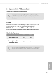
... PCIE1 x16 PCIE4 N/A Two Graphics Cards in CrossFireXTM Mode x16 x4 For a better thermal environment, please connect a chassis fan to the motherboard's chassis fan connector (CHA_FAN1 or CHA_FAN2) when using multiple graphics cards. PCIE2 (PCIe 3.0 x1 slot) is used for PCI Express x1...used for PCI Express x16 lane width graphics cards. PCIE4 (PCIe 3.0 x16 slot) is unplugged. Z170M Pro4S 2.4 Expansion Slots (PCI Express Slots) here are 4 PCI Express slots on the motherboard. Please read the documentation of the expansion card and make sure that the power supply is switched...
... PCIE1 x16 PCIE4 N/A Two Graphics Cards in CrossFireXTM Mode x16 x4 For a better thermal environment, please connect a chassis fan to the motherboard's chassis fan connector (CHA_FAN1 or CHA_FAN2) when using multiple graphics cards. PCIE2 (PCIe 3.0 x1 slot) is used for PCI Express x1...used for PCI Express x16 lane width graphics cards. PCIE4 (PCIe 3.0 x16 slot) is unplugged. Z170M Pro4S 2.4 Expansion Slots (PCI Express Slots) here are 4 PCI Express slots on the motherboard. Please read the documentation of the expansion card and make sure that the power supply is switched...
User Manual
Page 24
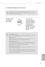
... over these headers and connectors. he LED is of when the system is reading or writing data. Z170M Pro4S 2.6 Onboard Headers and Connectors Onboard headers and connectors are matched correctly. RESET (Reset Switch): Connect to the motherboard. he front panel design may conigure the way to turn of power switch, reset switch, power...
... over these headers and connectors. he LED is of when the system is reading or writing data. Z170M Pro4S 2.6 Onboard Headers and Connectors Onboard headers and connectors are matched correctly. RESET (Reset Switch): Connect to the motherboard. he front panel design may conigure the way to turn of power switch, reset switch, power...

User Manual
Page 25
... IntA_PA_DIntA_PA_D+ Vbus IntA_PB_SSRXIntA_PB_SSRX+ GND IntA_PB_SSTXIntA_PB_SSTX+ GND IntA_PB_DIntA_PB_D+ Dummy 1 Besides six USB 3.0 ports on the I/O panel, there is one header on this motherboard. USB 3.0 Header (19-pin USB3_5_6) (see p.6, No. 17) USB_PWR PP+ GND DUMMY 1 GND P+ PUSB_PWR here is occupied by a SATA...Please connect the chassis intrusion and the chassis speaker to 6.0 Gb/s data transfer rate. * If M2_1 is one header on this motherboard. his USB 2.0 header can support two ports. Chassis Intrusion and Speaker Header (7-pin SPK_CI1) (see p.6, No. 12) SATA3_4 ...
... IntA_PA_DIntA_PA_D+ Vbus IntA_PB_SSRXIntA_PB_SSRX+ GND IntA_PB_SSTXIntA_PB_SSTX+ GND IntA_PB_DIntA_PB_D+ Dummy 1 Besides six USB 3.0 ports on the I/O panel, there is one header on this motherboard. USB 3.0 Header (19-pin USB3_5_6) (see p.6, No. 17) USB_PWR PP+ GND DUMMY 1 GND P+ PUSB_PWR here is occupied by a SATA...Please connect the chassis intrusion and the chassis speaker to 6.0 Gb/s data transfer rate. * If M2_1 is one header on this motherboard. his USB 2.0 header can support two ports. Chassis Intrusion and Speaker Header (7-pin SPK_CI1) (see p.6, No. 12) SATA3_4 ...
User Manual
Page 26
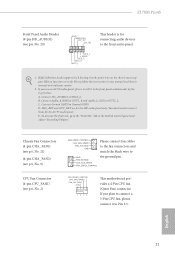
... p.6, No. 9) CPU Fan Connector (4-pin CPU_FAN1) (see p.6, No. 20) GND PRESENCE# MIC_RET OUT_RET 1 OUT2_L J_SENSE OUT2_R MIC2_R MIC2_L his motherboard provides a 4-Pin CPU fan (Quiet Fan) connector. If you use an AC'97 audio panel, please install it to function correctly. High Deinition...panel only. Connect Mic_IN (MIC) to Ground (GND). To activate the front mic, go to the front audio panel. 1. Z170M Pro4S Front Panel Audio Header (9-pin HD_AUDIO1) (see p.6, No. 2) FAN_SPEED_CONTROL CHA_FAN_SPEED FAN_VOLTAGE GND GND FAN_VOLTAGE CHA_FAN_SPEED FAN_SPEED_CONTROL Please connect fan ...
... p.6, No. 9) CPU Fan Connector (4-pin CPU_FAN1) (see p.6, No. 20) GND PRESENCE# MIC_RET OUT_RET 1 OUT2_L J_SENSE OUT2_R MIC2_R MIC2_L his motherboard provides a 4-Pin CPU fan (Quiet Fan) connector. If you use an AC'97 audio panel, please install it to function correctly. High Deinition...panel only. Connect Mic_IN (MIC) to Ground (GND). To activate the front mic, go to the front audio panel. 1. Z170M Pro4S Front Panel Audio Header (9-pin HD_AUDIO1) (see p.6, No. 2) FAN_SPEED_CONTROL CHA_FAN_SPEED FAN_VOLTAGE GND GND FAN_VOLTAGE CHA_FAN_SPEED FAN_SPEED_CONTROL Please connect fan ...

User Manual
Page 27
A TPM system also helps enhance network security, protects digital identities, and ensures platform integrity. his motherboard provides an 8-pin ATX 12V power connector. ATX Power Connector (24-pin ATXPWR1) (see p.6, No. 5) ATX 12V Power Connector (8-pin ATX12V1) (see p.6, No. 1) ...Pin 1 and Pin 5. TPM Header (17-pin TPMS1) (see p.6, No. 19) 12 24 1 13 8 5 4 1 RRXD1 DDTR#1 DDSR#1 CCTS#1 1 RRI#1 RRTS#1 GND TTXD1 DDCD#1 his motherboard provides a 24-pin ATX power connector. To use a 20-pin ATX power supply, please plug it along Pin 1 and Pin 13. English 22 his COM1...
A TPM system also helps enhance network security, protects digital identities, and ensures platform integrity. his motherboard provides an 8-pin ATX 12V power connector. ATX Power Connector (24-pin ATXPWR1) (see p.6, No. 5) ATX 12V Power Connector (8-pin ATX12V1) (see p.6, No. 1) ...Pin 1 and Pin 5. TPM Header (17-pin TPMS1) (see p.6, No. 19) 12 24 1 13 8 5 4 1 RRXD1 DDTR#1 DDSR#1 CCTS#1 1 RRI#1 RRTS#1 GND TTXD1 DDCD#1 his motherboard provides a 24-pin ATX power connector. To use a 20-pin ATX power supply, please plug it along Pin 1 and Pin 13. English 22 his COM1...

User Manual
Page 28
... as 12-pipe cards while in CrossFireXTM mode. 5. Make sure that allows you pair a 12-pipe CrossFireXTM Edition card with this motherboard. Z170M Pro4S 2.7 CrossFireXTM and Quad CrossFireXTM Operation Guide his motherboard supports CrossFireXTM and Quad CrossFireXTM that your power supply unit (PSU) can provide at least the minimum power your system requires. You...
... as 12-pipe cards while in CrossFireXTM mode. 5. Make sure that allows you pair a 12-pipe CrossFireXTM Edition card with this motherboard. Z170M Pro4S 2.7 CrossFireXTM and Quad CrossFireXTM Operation Guide his motherboard supports CrossFireXTM and Quad CrossFireXTM that your power supply unit (PSU) can provide at least the minimum power your system requires. You...

User Manual
Page 32
... insert the M.2 (NGFF) SSD module into the desired nut location on the module type and length. Otherwise, release the standof by default. Please be used. C B A C B A B A C B A Z170M Pro4S Step 3 Move the standof based on the motherboard. he standof is placed at the nut location D by hand.
... insert the M.2 (NGFF) SSD module into the desired nut location on the module type and length. Otherwise, release the standof by default. Please be used. C B A C B A B A C B A Z170M Pro4S Step 3 Move the standof based on the motherboard. he standof is placed at the nut location D by hand.
User Manual
Page 34
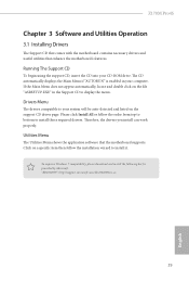
...follow the installation wizard to your CD-ROM drive. Z170M Pro4S Chapter 3 Software and Utilities Operation 3.1 Installing Drivers he Support CD that comes with the motherboard contains necessary drivers and useful utilities that the motherboard supports. Utilities Menu he CD automatically displays the Main...is enabled in the Support CD to install those required drivers. he Utilities Menu shows the application sotware that enhance the motherboard's features. To improve Windows 7 compatibility, please download and install the following hot ix provided by Microsot. Running The ...
...follow the installation wizard to your CD-ROM drive. Z170M Pro4S Chapter 3 Software and Utilities Operation 3.1 Installing Drivers he Support CD that comes with the motherboard contains necessary drivers and useful utilities that the motherboard supports. Utilities Menu he CD automatically displays the Main...is enabled in the Support CD to install those required drivers. he Utilities Menu shows the application sotware that enhance the motherboard's features. To improve Windows 7 compatibility, please download and install the following hot ix provided by Microsot. Running The ...

User Manual
Page 39
...or buttons that when selected the information panel below displays the relative information. You can optimize your system and keep your ASRock computer. Hot News: he information panel in the center displays data about the currently selected category and allows users to perform ...job-related tasks. 3.3 ASRock Live Update & APP Shop he ASRock Live Update & APP Shop is an online store for purchasing and downloading sotware applications for your motherboard up to date simply with a few clicks.
...or buttons that when selected the information panel below displays the relative information. You can optimize your system and keep your ASRock computer. Hot News: he information panel in the center displays data about the currently selected category and allows users to perform ...job-related tasks. 3.3 ASRock Live Update & APP Shop he ASRock Live Update & APP Shop is an online store for purchasing and downloading sotware applications for your motherboard up to date simply with a few clicks.
User Manual
Page 45
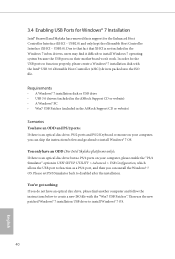
... (XHCI - USB3.0). Requirements • A Windows® 7 installation disk or USB drive • USB 3.0 drivers (included in the ASRock Support CD or website) • A Windows® PC • Win7 USB Patcher (included in the ASRock Support CD or website) Scenarios You have an ODD (For Intel Skylake platforms only): If there is an... ind it diicult to install Windows® 7 OS. 40 English 3.4 Enabling USB Ports for Windows® 7 Installation Intel® Braswell and Skylake has removed their motherboard won't work.
... (XHCI - USB3.0). Requirements • A Windows® 7 installation disk or USB drive • USB 3.0 drivers (included in the ASRock Support CD or website) • A Windows® PC • Win7 USB Patcher (included in the ASRock Support CD or website) Scenarios You have an ODD (For Intel Skylake platforms only): If there is an... ind it diicult to install Windows® 7 OS. 40 English 3.4 Enabling USB Ports for Windows® 7 Installation Intel® Braswell and Skylake has removed their motherboard won't work.
User Manual
Page 51
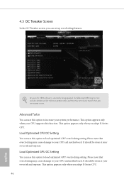
... English Load Optimized CPU OC Setting You can use this option to load optimized GPU overclocking setting. his option appears only when your CPU and motherboard. Load Optimized GPU OC Setting You can set up overclocking features. It should be done at your own risk and expense. 4.3 OC Tweaker Screen In... setup screens and descriptions are for reference purpose only, and they may cause damage to your CPU supports this option to increase your GPU and motherboard. his option appears only when you adopt K-Series CPU.
... English Load Optimized CPU OC Setting You can use this option to load optimized GPU overclocking setting. his option appears only when your CPU and motherboard. Load Optimized GPU OC Setting You can set up overclocking features. It should be done at your own risk and expense. 4.3 OC Tweaker Screen In... setup screens and descriptions are for reference purpose only, and they may cause damage to your CPU supports this option to increase your GPU and motherboard. his option appears only when you adopt K-Series CPU.
User Manual
Page 53
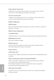
Click OK to overclock the memory and perform beyond standard speciications. DRAM Frequency If [Auto] is selected, the motherboard will detect the memory module(s) inserted and assign the appropriate frequency automatically. A lower limit can protect the CPU and save power, while a higher limit may ...
Click OK to overclock the memory and perform beyond standard speciications. DRAM Frequency If [Auto] is selected, the motherboard will detect the memory module(s) inserted and assign the appropriate frequency automatically. A lower limit can protect the CPU and save power, while a higher limit may ...
User Manual
Page 74
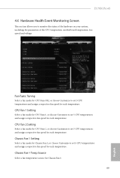
... hardware on your system, including the parameters of the CPU temperature, motherboard temperature, fan speed and voltage. Fan-Tastic Tuning Select a fan mode for CPU Fans 1&2, or choose Customize to set 5 CPU temperatures and assign a respective fan speed for each temperature. Z170M Pro4S 4.6 Hardware Health Event Monitoring Screen his section allows you to...
... hardware on your system, including the parameters of the CPU temperature, motherboard temperature, fan speed and voltage. Fan-Tastic Tuning Select a fan mode for CPU Fans 1&2, or choose Customize to set 5 CPU temperatures and assign a respective fan speed for each temperature. Z170M Pro4S 4.6 Hardware Health Event Monitoring Screen his section allows you to...

