

User Manual
Page 5
... 3 Software and Utilities Operation 41 3.1 Installing Drivers 41 3.2 Formula Drive 42 3.3 ASRock Live Update & APP Shop 46 3.3.1 UI Overview 46 3.3.2 Apps 47 3.3.3 BIOS & Drivers 50 3.3.4 Setting 51 3.4 Enabling USB Ports for ...Windows® 7 Installation 52 Chapter 4 UEFI SETUP UTILITY 55 4.1 Introduction 55 4.2 EZ Mode 56 4.3 Advanced Mode 57 4.3.1 UEFI Menu Bar 57 4.3.2 Navigation Keys 58 4.4 Main Screen 59 4.5 OC...
... 3 Software and Utilities Operation 41 3.1 Installing Drivers 41 3.2 Formula Drive 42 3.3 ASRock Live Update & APP Shop 46 3.3.1 UI Overview 46 3.3.2 Apps 47 3.3.3 BIOS & Drivers 50 3.3.4 Setting 51 3.4 Enabling USB Ports for ...Windows® 7 Installation 52 Chapter 4 UEFI SETUP UTILITY 55 4.1 Introduction 55 4.2 EZ Mode 56 4.3 Advanced Mode 57 4.3.1 UEFI Menu Bar 57 4.3.2 Navigation Keys 58 4.4 Main Screen 59 4.5 OC...

User Manual
Page 7
... • ASRock Z170M OC Formula Motherboard (Micro ATX Form Factor) • ASRock Z170M OC Formula Quick Installation Guide • ASRock Z170M OC Formula Support CD • 2 x Serial ATA (SATA) Data Cables (Optional) • 1 x I/O Panel Shield • 1 x ASRock Flexible SLI Bridge Connector Cable • 1 x Screw for purchasing ASRock Z170M OC Formula motherboard, a reliable motherboard produced under ASRock's consistently stringent quality control. Chapter 3 contains the operation guide of the BIOS setup...
... • ASRock Z170M OC Formula Motherboard (Micro ATX Form Factor) • ASRock Z170M OC Formula Quick Installation Guide • ASRock Z170M OC Formula Support CD • 2 x Serial ATA (SATA) Data Cables (Optional) • 1 x I/O Panel Shield • 1 x ASRock Flexible SLI Bridge Connector Cable • 1 x Screw for purchasing ASRock Z170M OC Formula motherboard, a reliable motherboard produced under ASRock's consistently stringent quality control. Chapter 3 contains the operation guide of the BIOS setup...

User Manual
Page 11
...• 1 x Direct Key Button BIOS • 2 x 128Mb AMI UEFI Legal BIOS with LED • V-ProbeTM: 1 x 7-set of maximum 1A (12W) fan power. • 1 x 24 pin ATX Power Connector • 1 x 8 pin 12V Power Connector (Hi-Density Power Connec- Z170M OC Formula Connector • 1 x COM Port... is supported. • 2 x USB 2.0 Headers (Support 4 USB 2.0 ports) (Supports ESD Protection (ASRock Full Spike Protection)) • 1 x USB 3.0 Header (Supports 2 USB 3.0 ports) (Supports ESD Protection (ASRock Full Spike Protection)) • 1 x Dr. Debug with LED • 1 x Power Switch with LED...
...• 1 x Direct Key Button BIOS • 2 x 128Mb AMI UEFI Legal BIOS with LED • V-ProbeTM: 1 x 7-set of maximum 1A (12W) fan power. • 1 x 24 pin ATX Power Connector • 1 x 8 pin 12V Power Connector (Hi-Density Power Connec- Z170M OC Formula Connector • 1 x COM Port... is supported. • 2 x USB 2.0 Headers (Support 4 USB 2.0 ports) (Supports ESD Protection (ASRock Full Spike Protection)) • 1 x USB 3.0 Header (Supports 2 USB 3.0 ports) (Supports ESD Protection (ASRock Full Spike Protection)) • 1 x Dr. Debug with LED • 1 x Power Switch with LED...

User Manual
Page 12
... may affect your system's stability, or even cause damage to page 52 for more detailed instructions. * For the updated Windows® 10 driver, please visit ASRock's website for possible damage caused by CPU temperature) • CPU/Chassis Fan multi-speed control • Voltage monitoring: +12V, +5V, +3.3V, CPU Vcore, GT_CPU, ... 10 64-bit / 8.1 64-bit / 7 32-bit / 7 64- bit * To install Windows® 7 OS, a modified installation disk with overclocking, including adjusting the setting in the BIOS, applying Untied Overclocking Technology, or using third-party overclocking tools.
... may affect your system's stability, or even cause damage to page 52 for more detailed instructions. * For the updated Windows® 10 driver, please visit ASRock's website for possible damage caused by CPU temperature) • CPU/Chassis Fan multi-speed control • Voltage monitoring: +12V, +5V, +3.3V, CPU Vcore, GT_CPU, ... 10 64-bit / 8.1 64-bit / 7 32-bit / 7 64- bit * To install Windows® 7 OS, a modified installation disk with overclocking, including adjusting the setting in the BIOS, applying Untied Overclocking Technology, or using third-party overclocking tools.

User Manual
Page 13
Z170M OC Formula 1.3 Motherboard Layout 1 2 3 4 USB 2.0 T: USB1 B: USB2 PS2 Keyboard /Mouse VOL_CON1 DISPLAY1 HDMI1 Clr CMOS ATX12V1 USB 3.1 T: USB31_TA_1 B: USB31_TC_1 Power 5 CPU_FAN2 Reset 6 + 7 - 8 MENU 9 ...M2_1 22 Purity CT5 SoundTM 3 CT4 CT3 CT2 CT1 Z170M OC Formula Intel SATA3_1 SATA3_3 23 SATA_EXP1 SATA_EXP0 PCIE2 Z170 24 25 Ultra M.2 26 PCIe Gen3 x4 27 SATA3_4 SATA3_5 HD_AUDIO1 1 1 PCIE3 T B1 T B2 1 SPK_PLED1 1 USB3_4 USB5_6 1 1 COM1 1 BIOS_A_LED1 CHA_FAN2 Dr. Debug BIOS BIOS BIOS_A1 BIOS_B1 A B BIOS_SEL1 PANEL1 PLED PWRBTN 1 ...
Z170M OC Formula 1.3 Motherboard Layout 1 2 3 4 USB 2.0 T: USB1 B: USB2 PS2 Keyboard /Mouse VOL_CON1 DISPLAY1 HDMI1 Clr CMOS ATX12V1 USB 3.1 T: USB31_TA_1 B: USB31_TC_1 Power 5 CPU_FAN2 Reset 6 + 7 - 8 MENU 9 ...M2_1 22 Purity CT5 SoundTM 3 CT4 CT3 CT2 CT1 Z170M OC Formula Intel SATA3_1 SATA3_3 23 SATA_EXP1 SATA_EXP0 PCIE2 Z170 24 25 Ultra M.2 26 PCIe Gen3 x4 27 SATA3_4 SATA3_5 HD_AUDIO1 1 1 PCIE3 T B1 T B2 1 SPK_PLED1 1 USB3_4 USB5_6 1 1 COM1 1 BIOS_A_LED1 CHA_FAN2 Dr. Debug BIOS BIOS BIOS_A1 BIOS_B1 A B BIOS_SEL1 PANEL1 PLED PWRBTN 1 ...

User Manual
Page 14
...288-pin DDR3 DIMM Slots (DDR3_A1, DDR3_B1) 3 CPU Fan Connector (CPU_FAN2) 4 V-ProbeTM (VOL_CON1) 5 Power Switch (PWR) 6 Reset Switch (RST) 7 Rapid OC Button (+) (PLUS) 8 Rapid OC Button (-) (MINUS) 9 Menu Button (MENU) 10 ATX Power Connector (ATXPWR1) 11 USB 3.0 Header (USB3_5_6) 12 Post Status Checker (PSC) 13 LN2 Mode Switch ...25 SATA Express Connector (SATA_EXP1) 26 SATA3 Connector (SATA3_5) 27 SATA3 Connector (SATA3_4) 28 System Panel Header (PANEL1) 29 BIOS Selection Switch (BIOS_SEL1) 30 Chassis Fan Connector (CHA_FAN2) 31 COM Port Header (COM1) 32 USB 2.0 Header (USB5_6) 8 English No.
...288-pin DDR3 DIMM Slots (DDR3_A1, DDR3_B1) 3 CPU Fan Connector (CPU_FAN2) 4 V-ProbeTM (VOL_CON1) 5 Power Switch (PWR) 6 Reset Switch (RST) 7 Rapid OC Button (+) (PLUS) 8 Rapid OC Button (-) (MINUS) 9 Menu Button (MENU) 10 ATX Power Connector (ATXPWR1) 11 USB 3.0 Header (USB3_5_6) 12 Post Status Checker (PSC) 13 LN2 Mode Switch ...25 SATA Express Connector (SATA_EXP1) 26 SATA3 Connector (SATA3_5) 27 SATA3 Connector (SATA3_4) 28 System Panel Header (PANEL1) 29 BIOS Selection Switch (BIOS_SEL1) 30 Chassis Fan Connector (CHA_FAN2) 31 COM Port Header (COM1) 32 USB 2.0 Header (USB5_6) 8 English No.

User Manual
Page 26
... CLRCMOS1 for 15 seconds, use a jumper cap to clear the CMOS when you just finish updating the BIOS, you must boot up the system first, and then shut it down before you update the BIOS. However, please do not clear the CMOS right after you do the clear-CMOS action. After waiting...
... CLRCMOS1 for 15 seconds, use a jumper cap to clear the CMOS when you just finish updating the BIOS, you must boot up the system first, and then shut it down before you update the BIOS. However, please do not clear the CMOS right after you do the clear-CMOS action. After waiting...
User Manual
Page 33
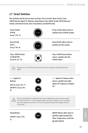
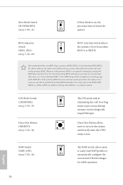
...the power supply. + / - Power Switch (PWR) (see p.7, No. 5) Power Power Switch allows users to quickly and easily adjust OC frequency in Rapid OC. Reset Switch (RST) (see p.7, No. 9) MENU MENU Button allow users to quickly turn on the system configuration, such as memory... Date/ Time, Temperature, and Voltage information. 27 English Z170M OC Formula 2.7 Smart Switches The motherboard has eleven smart switches: Power Switch, Reset Switch, Clear CMOS Switch, Rapid OC Buttons, Menu Button, Slow Mode Switch, BIOS Selection Switch, LN2 Mode Switch, Direct Key Button and XMP...
...the power supply. + / - Power Switch (PWR) (see p.7, No. 5) Power Power Switch allows users to quickly and easily adjust OC frequency in Rapid OC. Reset Switch (RST) (see p.7, No. 9) MENU MENU Button allow users to quickly turn on the system configuration, such as memory... Date/ Time, Temperature, and Voltage information. 27 English Z170M OC Formula 2.7 Smart Switches The motherboard has eleven smart switches: Power Switch, Reset Switch, Clear CMOS Switch, Rapid OC Buttons, Menu Button, Slow Mode Switch, BIOS Selection Switch, LN2 Mode Switch, Direct Key Button and XMP...
User Manual
Page 34
... the UEFI Setup Utility to duplicate a working copy of the BIOS files to the primary BIOS to identify which enhances the safety and stability of your system. This motherboard has two BIOS chips, a primary BIOS (BIOS_A) and a backup BIOS (BIOS_ B), which BIOS is on the primary BIOS. LN2 Mode Switch (LN2MODE1) (see p.7, No. 13) Direct Key Button...
... the UEFI Setup Utility to duplicate a working copy of the BIOS files to the primary BIOS to identify which enhances the safety and stability of your system. This motherboard has two BIOS chips, a primary BIOS (BIOS_A) and a backup BIOS (BIOS_ B), which BIOS is on the primary BIOS. LN2 Mode Switch (LN2MODE1) (see p.7, No. 13) Direct Key Button...

User Manual
Page 56
Click to select one or more details. Step 1 Please check the item information before update. Step 3 Click Update to update. 3.3.3 BIOS & Drivers Installing BIOS or Drivers When the "BIOS & Drivers" tab is selected, you want to start the update process. 50 English Please update them all soon. Click on Step 2 to see more items you will see a list of recommended or critical updates for the BIOS or drivers.
Click to select one or more details. Step 1 Please check the item information before update. Step 3 Click Update to update. 3.3.3 BIOS & Drivers Installing BIOS or Drivers When the "BIOS & Drivers" tab is selected, you want to start the update process. 50 English Please update them all soon. Click on Step 2 to see more items you will see a list of recommended or critical updates for the BIOS or drivers.

User Manual
Page 62
You can check the most crucial information of the system's current status. Function 1 Help 2 Load UEFI Defaults 3 Save Changes and Exit 4 Discard Changes 5 Change Language 6 Switch to "Advanced Mode" for more options. EZ mode is a dashboard which contains multiple readings of your system, such as CPU speed, DRAM frequency, SATA information, fan speed, etc. 4.2 EZ Mode The EZ Mode screen appears when you enter the BIOS setup program by default. No. Press or click the "Advanced Mode" button at the upper right corner of the screen to switch to Advanced Mode 56 English
You can check the most crucial information of the system's current status. Function 1 Help 2 Load UEFI Defaults 3 Save Changes and Exit 4 Discard Changes 5 Change Language 6 Switch to "Advanced Mode" for more options. EZ mode is a dashboard which contains multiple readings of your system, such as CPU speed, DRAM frequency, SATA information, fan speed, etc. 4.2 EZ Mode The EZ Mode screen appears when you enter the BIOS setup program by default. No. Press or click the "Advanced Mode" button at the upper right corner of the screen to switch to Advanced Mode 56 English

User Manual
Page 63
...the BIOS settings. To access the EZ Mode, press or click the "EZ Mode" button at the upper right corner of the screen. 4.3.1 UEFI Menu Bar The top of the screen has a menu bar with the following sections for the detailed configurations. Z170M OC Formula ...4.3 Advanced Mode The Advanced Mode provides more options to the following selections: Main For setting system time/date information OC Tweaker For overclocking configurations Advanced For advanced system configurations Tool Useful tools...
...the BIOS settings. To access the EZ Mode, press or click the "EZ Mode" button at the upper right corner of the screen. 4.3.1 UEFI Menu Bar The top of the screen has a menu bar with the following sections for the detailed configurations. Z170M OC Formula ...4.3 Advanced Mode The Advanced Mode provides more options to the following selections: Main For setting system time/date information OC Tweaker For overclocking configurations Advanced For advanced system configurations Tool Useful tools...

User Manual
Page 65
Z170M OC Formula 4.4 Main Screen When you enter the UEFI SETUP UTILITY, the Main screen will appear and display the system overview. Favorite Display your collection of BIOS items. Press F5 to add/remove your favorite items. 59 English
Z170M OC Formula 4.4 Main Screen When you enter the UEFI SETUP UTILITY, the Main screen will appear and display the system overview. Favorite Display your collection of BIOS items. Press F5 to add/remove your favorite items. 59 English

User Manual
Page 68
... a higher limit may improve performance. 62 English Stable Delay Configure the delay time after a period of time. OC Tweaking Enable this option for stable signal. Boot Performance Mode Select the performance state that the BIOS will be lowered after BCLK setting for better 3DMark performance. Long Duration Power Limit Configure Package Power...
... a higher limit may improve performance. 62 English Stable Delay Configure the delay time after a period of time. OC Tweaking Enable this option for stable signal. Boot Performance Mode Select the performance state that the BIOS will be lowered after BCLK setting for better 3DMark performance. Long Duration Power Limit Configure Package Power...

User Manual
Page 95
... this function. Please setup network configuration before using Internet Flash. *For BIOS backup and recovery purpose, it is recommended to download the UEFI firmware. 89 English Z170M OC Formula Intel MEI Recovery Configure Intel ME (Management Engine) recovery. DHCP (Auto IP), Auto ASRock Internet Flash downloads and updates the latest UEFI firmware version from our...
... this function. Please setup network configuration before using Internet Flash. *For BIOS backup and recovery purpose, it is recommended to download the UEFI firmware. 89 English Z170M OC Formula Intel MEI Recovery Configure Intel ME (Management Engine) recovery. DHCP (Auto IP), Auto ASRock Internet Flash downloads and updates the latest UEFI firmware version from our...


