
User Manual
Page 2
... business, loss of data, interruption of business and the like), even if ASRock has been advised of the possibility of such damages arising from any means, except duplication of this motherboard contains Perchlorate, a toxic substance controlled in the documentation or product. CALIFORNIA, ...USA ONLY The Lithium battery adopted on this documentation, ASRock does not provide warranty of any kind, either expressed or ...
... business, loss of data, interruption of business and the like), even if ASRock has been advised of the possibility of such damages arising from any means, except duplication of this motherboard contains Perchlorate, a toxic substance controlled in the documentation or product. CALIFORNIA, ...USA ONLY The Lithium battery adopted on this documentation, ASRock does not provide warranty of any kind, either expressed or ...
User Manual
Page 4
Contents Chapter 1 Introduction 1 1.1 Package Contents 1 1.2 Specifications 2 1.3 Motherboard Layout 6 1.4 I/O Panel 8 1.5 WiFi-802.11ac Module and ASRock WiFi 2.4/5 GHz Antenna 10 Chapter 2 Installation 15 2.1 Installing the CPU 16 2.2 Installing the CPU Fan and ... Jumpers Setup 23 2.6 Onboard Headers and Connectors 24 Chapter 3 Software and Utilities Operation 28 3.1 Installing Drivers 28 3.2 A-Tuning 29 3.3 ASRock Live Update & APP Shop 33 3.3.1 UI Overview 33 3.3.2 Apps 34 3.3.3 BIOS & Drivers 37 3.3.4 Setting 38 3.4 Enabling USB Ports for Windows®...
Contents Chapter 1 Introduction 1 1.1 Package Contents 1 1.2 Specifications 2 1.3 Motherboard Layout 6 1.4 I/O Panel 8 1.5 WiFi-802.11ac Module and ASRock WiFi 2.4/5 GHz Antenna 10 Chapter 2 Installation 15 2.1 Installing the CPU 16 2.2 Installing the CPU Fan and ... Jumpers Setup 23 2.6 Onboard Headers and Connectors 24 Chapter 3 Software and Utilities Operation 28 3.1 Installing Drivers 28 3.2 A-Tuning 29 3.3 ASRock Live Update & APP Shop 33 3.3.1 UI Overview 33 3.3.2 Apps 34 3.3.3 BIOS & Drivers 37 3.3.4 Setting 38 3.4 Enabling USB Ports for Windows®...
User Manual
Page 6
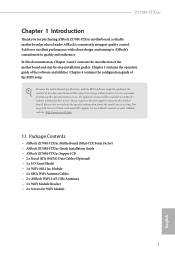
ASRock website http://www.asrock.com. 1.1 Package Contents • ASRock Z170M-ITX/ac Motherboard (Mini-ITX Form Factor) • ASRock Z170M-ITX/ac Quick Installation Guide • ASRock Z170M-ITX/ac Support CD • 2 x Serial ATA (SATA) Data Cables (Optional) • 1 x I/O Panel Shield • 1 x WiFi-802.11ac Module • 2 x SMA WiFi Antenna Cables • 2 x ASRock WiFi 2.4/5 GHz Antennas • 1 x WiFi Module Bracket • 2 x Screws for specific information about...
ASRock website http://www.asrock.com. 1.1 Package Contents • ASRock Z170M-ITX/ac Motherboard (Mini-ITX Form Factor) • ASRock Z170M-ITX/ac Quick Installation Guide • ASRock Z170M-ITX/ac Support CD • 2 x Serial ATA (SATA) Data Cables (Optional) • 1 x I/O Panel Shield • 1 x WiFi-802.11ac Module • 2 x SMA WiFi Antenna Cables • 2 x ASRock WiFi 2.4/5 GHz Antennas • 1 x WiFi Module Bracket • 2 x Screws for specific information about...
User Manual
Page 11
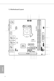
1.3 Motherboard Layout 1 2 3 PS2 Keyboard /Mouse Front USB 3.0 DDR4_A1 (64 bit, 288-pin module) DDR4_B1 (64 bit, 288-pin module) USB 2.0 T: USB1 B: USB2 17 DVI1 CHA_FAN1 CPU_FAN1 ... Top: RJ-45 LAN USB 3.0 T: USB3 B: USB4 Top: RJ-45 LAN USB 3.0 T: USB5 B: USB6 HD_AUDIO1 AUDIO CODEC 1 RoHS PCI Express 3.0 Intel Z170 MINI_PCIE1 128Mb BIOS Z170M-ITX/ac PCIE1 16 15 14 13 12 11 SATA3_3 SATA3_2 SATA3_1 SATA3_0 SPEAKER1 1 5 USB3_7_8 6 1 7 TPMS1 8 PANEL1 PLED PWRBTN HDLED RESET CLRMOS1 9 1 1 1 1 10 CI1 Top: LINE IN...
1.3 Motherboard Layout 1 2 3 PS2 Keyboard /Mouse Front USB 3.0 DDR4_A1 (64 bit, 288-pin module) DDR4_B1 (64 bit, 288-pin module) USB 2.0 T: USB1 B: USB2 17 DVI1 CHA_FAN1 CPU_FAN1 ... Top: RJ-45 LAN USB 3.0 T: USB3 B: USB4 Top: RJ-45 LAN USB 3.0 T: USB5 B: USB6 HD_AUDIO1 AUDIO CODEC 1 RoHS PCI Express 3.0 Intel Z170 MINI_PCIE1 128Mb BIOS Z170M-ITX/ac PCIE1 16 15 14 13 12 11 SATA3_3 SATA3_2 SATA3_1 SATA3_0 SPEAKER1 1 5 USB3_7_8 6 1 7 TPMS1 8 PANEL1 PLED PWRBTN HDLED RESET CLRMOS1 9 1 1 1 1 10 CI1 Top: LINE IN...
User Manual
Page 15
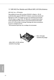
...) adapter to the environment. ASRock WiFi 2.4/5 GHz Antennas (included in the package) WiFi + BT Module (included in the package) English 10 BT 4.0 also includes Low Energy Technology and ensures extraordinary low power consumption for WiFi 802.11 a/b/g/n/ac connectivity standards and Bluetooth v4.0.... 1.5 WiFi-802.11ac Module and ASRock WiFi 2.4/5 GHz Antenna WiFi-802.11ac + BT Module This motherboard comes with an exclusive WiFi 802.11 a/b/g/n/ac + BT v4.0 module that adds a whole...
...) adapter to the environment. ASRock WiFi 2.4/5 GHz Antennas (included in the package) WiFi + BT Module (included in the package) English 10 BT 4.0 also includes Low Energy Technology and ensures extraordinary low power consumption for WiFi 802.11 a/b/g/n/ac connectivity standards and Bluetooth v4.0.... 1.5 WiFi-802.11ac Module and ASRock WiFi 2.4/5 GHz Antenna WiFi-802.11ac + BT Module This motherboard comes with an exclusive WiFi 802.11 a/b/g/n/ac + BT v4.0 module that adds a whole...
User Manual
Page 20
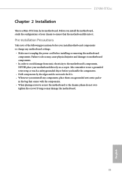
... a safety grounded object before installing or removing the motherboard components. Z170M-ITX/ac Chapter 2 Installation This is a Mini-ITX form factor motherboard. Pre-installation Precautions Take note of your chassis to the motherboard's components, NEVER place your motherboard directly on a grounded anti-static pad or in the bag that the motherboard fits into it. Failure to do not touch...
... a safety grounded object before installing or removing the motherboard components. Z170M-ITX/ac Chapter 2 Installation This is a Mini-ITX form factor motherboard. Pre-installation Precautions Take note of your chassis to the motherboard's components, NEVER place your motherboard directly on a grounded anti-static pad or in the bag that the motherboard fits into it. Failure to do not touch...
User Manual
Page 23
The cover must be placed if you wish to return the motherboard for after service. 18 English Please save and replace the cover if the processor is removed.
The cover must be placed if you wish to return the motherboard for after service. 18 English Please save and replace the cover if the processor is removed.
User Manual
Page 25
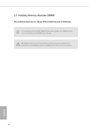
The DIMM only fits in one correct orientation. otherwise, this motherboard and DIMM may be damaged. It is not allowed to the motherboard and the DIMM if you force the DIMM into a DDR4 slot; It will cause permanent damage to install a DDR, DDR2 or DDR3 memory module into the slot at incorrect orientation. 20 English 2.3 Installing Memory Modules (DIMM) This motherboard provides two 288-pin DDR4 (Double Data Rate 4) DIMM slots.
The DIMM only fits in one correct orientation. otherwise, this motherboard and DIMM may be damaged. It is not allowed to the motherboard and the DIMM if you force the DIMM into a DDR4 slot; It will cause permanent damage to install a DDR, DDR2 or DDR3 memory module into the slot at incorrect orientation. 20 English 2.3 Installing Memory Modules (DIMM) This motherboard provides two 288-pin DDR4 (Double Data Rate 4) DIMM slots.

User Manual
Page 27
... for PCI Express x16 lane width graphics cards. PCIe slot: PCIE1 (PCIe 3.0 x16 slot) is 1 PCI Express slot and 1 mini-PCI Express slot on the motherboard. 2.4 Expansion Slots (PCI Express Slots) There is used for WiFi module. * This Mini-PCI Express Slot supports WiFi and mSATA devices. 22 English
... for PCI Express x16 lane width graphics cards. PCIe slot: PCIE1 (PCIe 3.0 x16 slot) is 1 PCI Express slot and 1 mini-PCI Express slot on the motherboard. 2.4 Expansion Slots (PCI Express Slots) There is used for WiFi module. * This Mini-PCI Express Slot supports WiFi and mSATA devices. 22 English
User Manual
Page 29
... to this header, make sure the wire assignments and the pin assignments are NOT jumpers. The front panel design may configure the way to the motherboard. When connecting your system using the power switch. Note the positive and negative pins before connecting the cables. You may differ by chassis. Do NOT...
... to this header, make sure the wire assignments and the pin assignments are NOT jumpers. The front panel design may configure the way to the motherboard. When connecting your system using the power switch. Note the positive and negative pins before connecting the cables. You may differ by chassis. Do NOT...
User Manual
Page 30
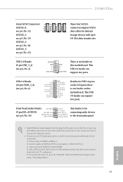
... Audio_R (RIN) to OUT2_R and Audio_L (LIN) to the front panel audio header by the steps below: A. C. If you use an AC'97 audio panel, please install it to OUT2_L. Connect Ground (GND) to the "FrontMic" Tab in our manual and chassis manual to 6.0...4) USB 3.0 Header (19-pin USB3_7_8) (see p.6, No. 6) DUMMY GND P+ P- High Definition Audio supports Jack Sensing, but the panel wire on this motherboard. You don't need to function correctly. Z170M-ITX/ac Serial ATA3 Connectors (SATA3_0: see p.6, No. 12) (SATA3_1: see p.6, No. 13) (SATA3_2: see p.6, No. 14) (SATA3_3: see p.6, No....
... Audio_R (RIN) to OUT2_R and Audio_L (LIN) to the front panel audio header by the steps below: A. C. If you use an AC'97 audio panel, please install it to OUT2_L. Connect Ground (GND) to the "FrontMic" Tab in our manual and chassis manual to 6.0...4) USB 3.0 Header (19-pin USB3_7_8) (see p.6, No. 6) DUMMY GND P+ P- High Definition Audio supports Jack Sensing, but the panel wire on this motherboard. You don't need to function correctly. Z170M-ITX/ac Serial ATA3 Connectors (SATA3_0: see p.6, No. 12) (SATA3_1: see p.6, No. 13) (SATA3_2: see p.6, No. 14) (SATA3_3: see p.6, No....
User Manual
Page 31
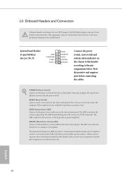
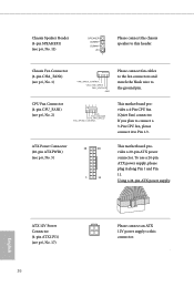
Chassis Fan Connector (4-pin CHA_FAN1) (see p.6, No. 2) 4 3 21 GND FAN_VOLTAGE CPU_FAN_SPEED FAN_SPEED_CONTROL This motherboard provides a 4-Pin CPU fan (Quiet Fan) connector. If you plan to connect a 3-Pin CPU fan, please connect it along Pin 1 and Pin 11. Using a 24-.... 11) SPEAKER DUMMY DUMMY +5V 1 Please connect the chassis speaker to this connector. ATX Power Connector (20-pin ATXPWR1) (see p.6, No. 5) 10 20 1 11 This motherboard provides a 20-pin ATX power connector.
Chassis Fan Connector (4-pin CHA_FAN1) (see p.6, No. 2) 4 3 21 GND FAN_VOLTAGE CPU_FAN_SPEED FAN_SPEED_CONTROL This motherboard provides a 4-Pin CPU fan (Quiet Fan) connector. If you plan to connect a 3-Pin CPU fan, please connect it along Pin 1 and Pin 11. Using a 24-.... 11) SPEAKER DUMMY DUMMY +5V 1 Please connect the chassis speaker to this connector. ATX Power Connector (20-pin ATXPWR1) (see p.6, No. 5) 10 20 1 11 This motherboard provides a 20-pin ATX power connector.

User Manual
Page 32
PCIRST# FRAME PCICLK This connector supports Trusted Platform Module (TPM) system, which can securely store keys, digital certificates, passwords, and data. English 27 This feature requires a chassis with chassis intrusion detection design. A TPM system also helps enhance network security, protects digital identities, and ensures platform integrity. Z170M-ITX/ac Chassis Intrusion Header (2-pin CI1) (see p.6, No. 10) TPM Header (17-pin TPMS1) (see p.6, No. 7) 1 GND Signal This motherboard supports CASE OPEN detection feature that detects if the chassis cove has been removed.
PCIRST# FRAME PCICLK This connector supports Trusted Platform Module (TPM) system, which can securely store keys, digital certificates, passwords, and data. English 27 This feature requires a chassis with chassis intrusion detection design. A TPM system also helps enhance network security, protects digital identities, and ensures platform integrity. Z170M-ITX/ac Chassis Intrusion Header (2-pin CI1) (see p.6, No. 10) TPM Header (17-pin TPMS1) (see p.6, No. 7) 1 GND Signal This motherboard supports CASE OPEN detection feature that detects if the chassis cove has been removed.
User Manual
Page 33
... "ASRSETUP.EXE" in your CD-ROM drive. Chapter 3 Software and Utilities Operation 3.1 Installing Drivers The Support CD that comes with the motherboard contains necessary drivers and useful utilities that the motherboard supports. Drivers Menu The drivers compatible to display the menu. Click on the support CD driver page. Therefore, the drivers you... CD To begin using the support CD, insert the CD into your computer. Utilities Menu The Utilities Menu shows the application software that enhance the motherboard's features.
... "ASRSETUP.EXE" in your CD-ROM drive. Chapter 3 Software and Utilities Operation 3.1 Installing Drivers The Support CD that comes with the motherboard contains necessary drivers and useful utilities that the motherboard supports. Drivers Menu The drivers compatible to display the menu. Click on the support CD driver page. Therefore, the drivers you... CD To begin using the support CD, insert the CD into your computer. Utilities Menu The Utilities Menu shows the application software that enhance the motherboard's features.
User Manual
Page 38
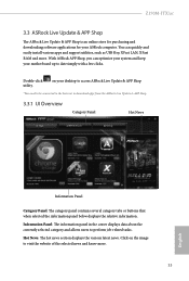
Z170M-ITX/ac 3.3 ASRock Live Update & APP Shop The ASRock Live Update & APP Shop is an online store for purchasing and downloading software applications for your motherboard up to date simply with a few clicks. With ASRock APP Shop, you can quickly and easily install various apps and support utilities, such...Panel: The information panel in the center displays data about the currently selected category and allows users to download apps from the ASRock Live Update & APP Shop. 3.3.1 UI Overview Category Panel Hot News Information Panel Category Panel: The category panel contains several ...
Z170M-ITX/ac 3.3 ASRock Live Update & APP Shop The ASRock Live Update & APP Shop is an online store for purchasing and downloading software applications for your motherboard up to date simply with a few clicks. With ASRock APP Shop, you can quickly and easily install various apps and support utilities, such...Panel: The information panel in the center displays data about the currently selected category and allows users to download apps from the ASRock Live Update & APP Shop. 3.3.1 UI Overview Category Panel Hot News Information Panel Category Panel: The category panel contains several ...
User Manual
Page 44
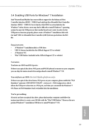
... that XHCI is an optical disc drive, PS/2 ports and PS/2 Keyboard or mouse on your computer, please enable the "PS/2 Simulator" option in the ASRock Support CD or website) Scenarios You have an ODD (For Intel Skylake platforms only): If there is an optical disc drive but no PS/2 ports..., which allows the USB port to create a new ISO file with the Intel® USB 3.0 eXtensible Host Controller (xHCI) drivers packed into the ISO file. Z170M-ITX/ac 3.4 Enabling USB Ports for Windows® 7 Installation Intel® Braswell and Skylake has removed their motherboard won't work.
... that XHCI is an optical disc drive, PS/2 ports and PS/2 Keyboard or mouse on your computer, please enable the "PS/2 Simulator" option in the ASRock Support CD or website) Scenarios You have an ODD (For Intel Skylake platforms only): If there is an optical disc drive but no PS/2 ports..., which allows the USB port to create a new ISO file with the Intel® USB 3.0 eXtensible Host Controller (xHCI) drivers packed into the ISO file. Z170M-ITX/ac 3.4 Enabling USB Ports for Windows® 7 Installation Intel® Braswell and Skylake has removed their motherboard won't work.
User Manual
Page 50
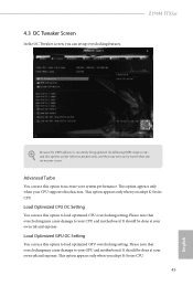
... system performance. Load Optimized GPU OC Setting You can use this option to increase your CPU supports this option to your CPU and motherboard. Please note that overclocking may cause damage to load optimized CPU overclocking setting. 4.3 OC Tweaker Screen In the OC Tweaker screen, ...You can set up overclocking features. Please note that overclocking may not exactly match what you see on your own risk and expense. Z170M-ITX/ac Because the UEFI software is constantly being updated, the following UEFI setup screens and descriptions are for reference purpose only, and they ...
... system performance. Load Optimized GPU OC Setting You can use this option to increase your CPU supports this option to your CPU and motherboard. Please note that overclocking may cause damage to load optimized CPU overclocking setting. 4.3 OC Tweaker Screen In the OC Tweaker screen, ...You can set up overclocking features. Please note that overclocking may not exactly match what you see on your own risk and expense. Z170M-ITX/ac Because the UEFI software is constantly being updated, the following UEFI setup screens and descriptions are for reference purpose only, and they ...
User Manual
Page 53
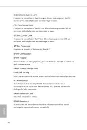
.... Increasing the BCLK will detect the memory module(s) inserted and assign the appropriate frequency automatically. 48 English BCLK Frequency The CPU speed is selected, the motherboard will increase the internal CPU clock speed but also affect the clock speed of other components. A lower limit can protect the CPU and save power...
.... Increasing the BCLK will detect the memory module(s) inserted and assign the appropriate frequency automatically. 48 English BCLK Frequency The CPU speed is selected, the motherboard will increase the internal CPU clock speed but also affect the clock speed of other components. A lower limit can protect the CPU and save power...
User Manual
Page 75
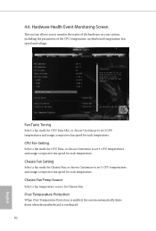
... fan temperature source for Chassis Fan. Over Temperature Protection When Over Temperature Protection is enabled, the system automatically shuts down when the motherboard is overheated. 70 English Chassis Fan Setting Select a fan mode for Chassis Fan, or choose Customize to set 5 CPU temperatures ...CPU Fans 1&2, or choose Customize to monitor the status of the hardware on your system, including the parameters of the CPU temperature, motherboard temperature, fan speed and voltage. 4.6 Hardware Health Event Monitoring Screen This section allows you to set 5 CPU temperatures and assign a...
... fan temperature source for Chassis Fan. Over Temperature Protection When Over Temperature Protection is enabled, the system automatically shuts down when the motherboard is overheated. 70 English Chassis Fan Setting Select a fan mode for Chassis Fan, or choose Customize to set 5 CPU temperatures ...CPU Fans 1&2, or choose Customize to monitor the status of the hardware on your system, including the parameters of the CPU temperature, motherboard temperature, fan speed and voltage. 4.6 Hardware Health Event Monitoring Screen This section allows you to set 5 CPU temperatures and assign a...

