
User Manual
Page 2
...for identification or explanation and to the implied warranties or conditions of this documentation. Products and corporate names appearing in this motherboard contains Perchlorate, a toxic substance controlled in any form or by any kind, either expressed or implied, including but not...the following two conditions: (1) this device may not cause harmful interference, and (2) this documentation may cause undesired operation. ASRock assumes no event shall ASRock, its directors, officers, employees, or agents be constructed as a commitment by the purchaser for backup purpose, without ...
...for identification or explanation and to the implied warranties or conditions of this documentation. Products and corporate names appearing in this motherboard contains Perchlorate, a toxic substance controlled in any form or by any kind, either expressed or implied, including but not...the following two conditions: (1) this device may not cause harmful interference, and (2) this documentation may cause undesired operation. ASRock assumes no event shall ASRock, its directors, officers, employees, or agents be constructed as a commitment by the purchaser for backup purpose, without ...

User Manual
Page 4
Contents Chapter 1 Introduction 1 1.1 Package Contents 1 1.2 Specifications 2 1.3 Motherboard Layout 6 1.4 I/O Panel 8 Chapter 2 Installation 10 2.1 Installing the CPU 11 2.2 Installing the CPU Fan and Heatsink 14 2.3 Installing Memory Modules (DIMM) 15 2.4 Expansion Slots (PCI Express ... Graphics Cards 24 2.7.2 Driver Installation and Setup 26 2.8 M.2_SSD (NGFF) Module Installation Guide 27 Chapter 3 Software and Utilities Operation 30 3.1 Installing Drivers 30 3.2 A-Tuning 31 3.3 ASRock Live Update & APP Shop 35 3.3.1 UI Overview 35 3.3.2 Apps 36
Contents Chapter 1 Introduction 1 1.1 Package Contents 1 1.2 Specifications 2 1.3 Motherboard Layout 6 1.4 I/O Panel 8 Chapter 2 Installation 10 2.1 Installing the CPU 11 2.2 Installing the CPU Fan and Heatsink 14 2.3 Installing Memory Modules (DIMM) 15 2.4 Expansion Slots (PCI Express ... Graphics Cards 24 2.7.2 Driver Installation and Setup 26 2.8 M.2_SSD (NGFF) Module Installation Guide 27 Chapter 3 Software and Utilities Operation 30 3.1 Installing Drivers 30 3.2 A-Tuning 31 3.3 ASRock Live Update & APP Shop 35 3.3.1 UI Overview 35 3.3.2 Apps 36

User Manual
Page 6
... step-by-step installation guides. It delivers excellent performance with robust design conforming to ASRock's commitment to change without further notice. ASRock website http://www.asrock.com. 1.1 Package Contents • ASRock Z170 Pro4 Motherboard (ATX Form Factor) • ASRock Z170 Pro4 Quick Installation Guide • ASRock Z170 Pro4 Support CD • 2 x Serial ATA (SATA) Data Cables (Optional) • 1 x I/O Panel Shield • 1 x Screw for...
... step-by-step installation guides. It delivers excellent performance with robust design conforming to ASRock's commitment to change without further notice. ASRock website http://www.asrock.com. 1.1 Package Contents • ASRock Z170 Pro4 Motherboard (ATX Form Factor) • ASRock Z170 Pro4 Quick Installation Guide • ASRock Z170 Pro4 Support CD • 2 x Serial ATA (SATA) Data Cables (Optional) • 1 x I/O Panel Shield • 1 x Screw for...

User Manual
Page 11
1.3 Motherboard Layout ATX12V1 PS2 Keyboard /Mouse USB 3.0 T: USB1 B: USB2 HDMI1 DDR4_A1 (64 bit, 288-pin module) DDR4_A2 (64 bit, 288-pin module) DDR4_B1 (64 bit, 288-... Bottom: CTR BASS Top: LINE IN Center: FRONT Bottom: MIC IN USB 3.0 T: USB3 B: USB4 USB 3.0 T: USB5 B: USB6 Top: RJ-45 PCIE_PWR1 CPU_FAN1 USB3_7_8 CHA_FAN3 PCIE1 Z170 Pro4 PCIE2 PCI Express 3.0 Ultra M.2 PCIe Gen3 x4 CT5 CT4 CT3 CT2 CT1 M2_1 1 Front USB 3.0 HD_AUDIO1 1 PCIE3 PCIE4 RoHS CLRMOS1 1 Intel...
1.3 Motherboard Layout ATX12V1 PS2 Keyboard /Mouse USB 3.0 T: USB1 B: USB2 HDMI1 DDR4_A1 (64 bit, 288-pin module) DDR4_A2 (64 bit, 288-pin module) DDR4_B1 (64 bit, 288-... Bottom: CTR BASS Top: LINE IN Center: FRONT Bottom: MIC IN USB 3.0 T: USB3 B: USB4 USB 3.0 T: USB5 B: USB6 Top: RJ-45 PCIE_PWR1 CPU_FAN1 USB3_7_8 CHA_FAN3 PCIE1 Z170 Pro4 PCIE2 PCI Express 3.0 Ultra M.2 PCIe Gen3 x4 CT5 CT4 CT3 CT2 CT1 M2_1 1 Front USB 3.0 HD_AUDIO1 1 PCIE3 PCIE4 RoHS CLRMOS1 1 Intel...
User Manual
Page 15
...remember to unplug the power cord before you install the motherboard, study the configuration of the following precautions before installing or removing the motherboard components. Failure to do not touch the ICs. • Whenever you uninstall any motherboard settings. • Make sure to use a grounded ... object before you handle the components. • Hold components by the edges and do so may damage the motherboard. 10 English Before you install motherboard components or change any components, place them on a carpet. Chapter 2 Installation This is an ATX form factor...
...remember to unplug the power cord before you install the motherboard, study the configuration of the following precautions before installing or removing the motherboard components. Failure to do not touch the ICs. • Whenever you uninstall any motherboard settings. • Make sure to use a grounded ... object before you handle the components. • Hold components by the edges and do so may damage the motherboard. 10 English Before you install motherboard components or change any components, place them on a carpet. Chapter 2 Installation This is an ATX form factor...
User Manual
Page 18
Z170 Pro4 Please save and replace the cover if the processor is removed. The cover must be placed if you wish to return the motherboard for after service. 13 English
Z170 Pro4 Please save and replace the cover if the processor is removed. The cover must be placed if you wish to return the motherboard for after service. 13 English
User Manual
Page 20
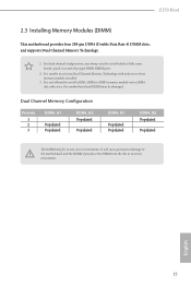
... DDR3 memory module into the slot at incorrect orientation. Z170 Pro4 2.3 Installing Memory Modules (DIMM) This motherboard provides four 288-pin DDR4 (Double Data Rate 4) DIMM slots, and supports Dual Channel Memory Technology. 1. It will cause permanent damage to the motherboard and the DIMM if you always need to activate Dual... module installed. 3. It is unable to install identical (the same brand, speed, size and chip-type) DDR4 DIMM pairs. 2. otherwise, this motherboard and DIMM may be damaged. For dual channel configuration, you force the DIMM into a DDR4 slot;
... DDR3 memory module into the slot at incorrect orientation. Z170 Pro4 2.3 Installing Memory Modules (DIMM) This motherboard provides four 288-pin DDR4 (Double Data Rate 4) DIMM slots, and supports Dual Channel Memory Technology. 1. It will cause permanent damage to the motherboard and the DIMM if you always need to activate Dual... module installed. 3. It is unable to install identical (the same brand, speed, size and chip-type) DDR4 DIMM pairs. 2. otherwise, this motherboard and DIMM may be damaged. For dual channel configuration, you force the DIMM into a DDR4 slot;
User Manual
Page 22
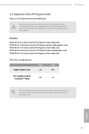
... Graphics Card PCIE2 x16 PCIE4 N/A Two Graphics Cards in CrossFireXTM Mode x16 x4 For a better thermal environment, please connect a chassis fan to the motherboard's chassis fan connector (CHA_FAN1, CHA_FAN2 or CHA_FAN3) when using multiple graphics cards. English 17 PCIE5 (PCIe 3.0 x1 slot) is used for the ... PCI Express x16 lane width graphics cards. PCIE2 (PCIe 3.0 x16 slot) is used for PCI Express x4 lane width graphics cards. Z170 Pro4 2.4 Expansion Slots (PCI Express Slots) There are 5 PCI Express slots on the motherboard. PCIE3 (PCIe 3.0 x1 slot) is unplugged.
... Graphics Card PCIE2 x16 PCIE4 N/A Two Graphics Cards in CrossFireXTM Mode x16 x4 For a better thermal environment, please connect a chassis fan to the motherboard's chassis fan connector (CHA_FAN1, CHA_FAN2 or CHA_FAN3) when using multiple graphics cards. English 17 PCIE5 (PCIe 3.0 x1 slot) is used for the ... PCI Express x16 lane width graphics cards. PCIE2 (PCIe 3.0 x16 slot) is used for PCI Express x4 lane width graphics cards. Z170 Pro4 2.4 Expansion Slots (PCI Express Slots) There are 5 PCI Express slots on the motherboard. PCIE3 (PCIe 3.0 x1 slot) is unplugged.
User Manual
Page 24
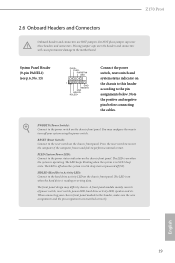
... may differ by chassis. The LED keeps blinking when the system is in S1/S3 sleep state. HDLED (Hard Drive Activity LED): Connect to the motherboard. Z170 Pro4 2.6 Onboard Headers and Connectors Onboard headers and connectors are matched correctly. Press the reset switch to restart the computer if the computer freezes and fails...
... may differ by chassis. The LED keeps blinking when the system is in S1/S3 sleep state. HDLED (Hard Drive Activity LED): Connect to the motherboard. Z170 Pro4 2.6 Onboard Headers and Connectors Onboard headers and connectors are matched correctly. Press the reset switch to restart the computer if the computer freezes and fails...
User Manual
Page 25
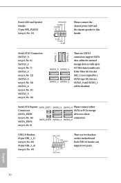
... see p.6, No. 10) SATA3_1 SATA3_0 SATA3_5 SATA3_4 SATA3_3 SATA3_2 These six SATA3 connectors support SATA data cables for internal storage devices with up to this motherboard. Each USB 2.0 header can support two ports. Power LED and Speaker Header (7-pin SPK_PLED1) (see p.6, No. 19) USB_PWR PP+ GND DUMMY 1 GND P+ PUSB_PWR There are...
... see p.6, No. 10) SATA3_1 SATA3_0 SATA3_5 SATA3_4 SATA3_3 SATA3_2 These six SATA3 connectors support SATA data cables for internal storage devices with up to this motherboard. Each USB 2.0 header can support two ports. Power LED and Speaker Header (7-pin SPK_PLED1) (see p.6, No. 19) USB_PWR PP+ GND DUMMY 1 GND P+ PUSB_PWR There are...

User Manual
Page 26
...If you use an AC'97 audio panel, please install it to OUT2_L. C. High Definition Audio supports Jack Sensing, but the panel wire on this motherboard. B. Connect Audio_R (RIN) to OUT2_R and Audio_L (LIN) to the front panel audio header by the steps below: A. E. Please follow the ...mic, go to install your system. 2. Connect Mic_IN (MIC) to Ground (GND). You don't need to connect them for the HD audio panel only. Z170 Pro4 USB 3.0 Header (19-pin USB3_7_8) (see p.6, No. 24) GND PRESENCE# MIC_RET OUT_RET 1 OUT2_L J_SENSE OUT2_R MIC2_R MIC2_L This header is one header on...
...If you use an AC'97 audio panel, please install it to OUT2_L. C. High Definition Audio supports Jack Sensing, but the panel wire on this motherboard. B. Connect Audio_R (RIN) to OUT2_R and Audio_L (LIN) to the front panel audio header by the steps below: A. E. Please follow the ...mic, go to install your system. 2. Connect Mic_IN (MIC) to Ground (GND). You don't need to connect them for the HD audio panel only. Z170 Pro4 USB 3.0 Header (19-pin USB3_7_8) (see p.6, No. 24) GND PRESENCE# MIC_RET OUT_RET 1 OUT2_L J_SENSE OUT2_R MIC2_R MIC2_L This header is one header on...
User Manual
Page 27
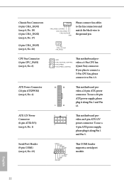
... GND TTXD1 DDCD#1 This COM1 header supports a serial port module. English 22 Serial Port Header (9-pin COM1) (see p.6, No. 1) 8 5 This motherboard pro- To use a 4 1 4-pin ATX power supply, please plug it along Pin 1 and Pin 5. GND FAN_VOLTAGE FAN_SPEED CPU Fan Connector (4-pin CPU_FAN1...) (see p.6, No. 4) 12 24 1 13 This motherboard provides a 24-pin ATX power connector. ATX Power Connector (24-pin ATXPWR1) (see p.6, No. 8) GND FAN_VOLTAGE_CONTROL FAN_SPEED FAN_SPEED_CONTROL This motherboard provides a 4-Pin CPU fan (Quiet Fan) connector. vides an 8-...
... GND TTXD1 DDCD#1 This COM1 header supports a serial port module. English 22 Serial Port Header (9-pin COM1) (see p.6, No. 1) 8 5 This motherboard pro- To use a 4 1 4-pin ATX power supply, please plug it along Pin 1 and Pin 5. GND FAN_VOLTAGE FAN_SPEED CPU Fan Connector (4-pin CPU_FAN1...) (see p.6, No. 4) 12 24 1 13 This motherboard provides a 24-pin ATX power connector. ATX Power Connector (24-pin ATXPWR1) (see p.6, No. 8) GND FAN_VOLTAGE_CONTROL FAN_SPEED FAN_SPEED_CONTROL This motherboard provides a 4-Pin CPU fan (Quiet Fan) connector. vides an 8-...

User Manual
Page 28
PCIe Power Connector (4-pin PCIE_PWR1) (see p.6, No. 21) 1 GND Signal This motherboard supports CASE OPEN detection feature that detects if the chassis cove has been removed. Z170 Pro4 Chassis Intrusion Header (2-pin CI1) (see p.6, No. 27) GND +12V DETECT Please connect a 4 pin molex power cable to this connector when more than three graphics ...
PCIe Power Connector (4-pin PCIE_PWR1) (see p.6, No. 21) 1 GND Signal This motherboard supports CASE OPEN detection feature that detects if the chassis cove has been removed. Z170 Pro4 Chassis Intrusion Header (2-pin CI1) (see p.6, No. 27) GND +12V DETECT Please connect a 4 pin molex power cable to this connector when more than three graphics ...
User Manual
Page 29
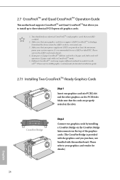
... on the top of the graphics cards. (The CrossFire Bridge is recommended to PCIE4 slot. 2.7 CrossFireXTM and Quad CrossFireXTM Operation Guide This motherboard supports CrossFireXTM and Quad CrossFireXTM that the cards are AMD certified. 2. Download the drivers from the AMD's website: www.amd.com 3.... It is provided with the graphics card you pair a 12-pipe CrossFireXTM Edition card with this motherboard. Please refer to three identical PCI Express x16 graphics cards. 1. You should only use a AMD certified PSU. Please refer to enable CrossFireXTM...
... on the top of the graphics cards. (The CrossFire Bridge is recommended to PCIE4 slot. 2.7 CrossFireXTM and Quad CrossFireXTM Operation Guide This motherboard supports CrossFireXTM and Quad CrossFireXTM that the cards are AMD certified. 2. Download the drivers from the AMD's website: www.amd.com 3.... It is provided with the graphics card you pair a 12-pipe CrossFireXTM Edition card with this motherboard. Please refer to three identical PCI Express x16 graphics cards. 1. You should only use a AMD certified PSU. Please refer to enable CrossFireXTM...
User Manual
Page 33
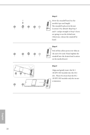
... yellow protective film on the module type and length. Step 5 Align and gently insert the M.2 (NGFF) SSD module into the desired nut location on the motherboard. Please be used. The standoff is placed at the nut location D by hand. Otherwise, release the standoff by default. Skip Step 3 and 4 and go straight...
... yellow protective film on the module type and length. Step 5 Align and gently insert the M.2 (NGFF) SSD module into the desired nut location on the motherboard. Please be used. The standoff is placed at the nut location D by hand. Otherwise, release the standoff by default. Skip Step 3 and 4 and go straight...
User Manual
Page 35
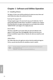
...the support CD driver page. Chapter 3 Software and Utilities Operation 3.1 Installing Drivers The Support CD that comes with the motherboard contains necessary drivers and useful utilities that the motherboard supports. Therefore, the drivers you install can work properly. "KB2720599": http://support.microsoft.com/kb/2720599/en-us 30... English Utilities Menu The Utilities Menu shows the application software that enhance the motherboard's features. Running The Support CD To begin using the support CD, insert the CD into your CD-ROM drive.
...the support CD driver page. Chapter 3 Software and Utilities Operation 3.1 Installing Drivers The Support CD that comes with the motherboard contains necessary drivers and useful utilities that the motherboard supports. Therefore, the drivers you install can work properly. "KB2720599": http://support.microsoft.com/kb/2720599/en-us 30... English Utilities Menu The Utilities Menu shows the application software that enhance the motherboard's features. Running The Support CD To begin using the support CD, insert the CD into your CD-ROM drive.
User Manual
Page 40
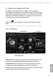
...*You need to be connected to the Internet to perform job-related tasks. Z170 Pro4 3.3 ASRock Live Update & APP Shop The ASRock Live Update & APP Shop is an online store for purchasing and downloading software applications for your motherboard up to visit the website of the selected news and know more . With... ASRock APP Shop, you can quickly and easily install various apps and support utilities, such as USB Key, ...
...*You need to be connected to the Internet to perform job-related tasks. Z170 Pro4 3.3 ASRock Live Update & APP Shop The ASRock Live Update & APP Shop is an online store for purchasing and downloading software applications for your motherboard up to visit the website of the selected news and know more . With... ASRock APP Shop, you can quickly and easily install various apps and support utilities, such as USB Key, ...
User Manual
Page 46
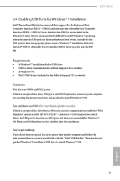
... Please set PS/S Simulator back to install Windows® 7 OS. 41 English Z170 Pro4 3.4 Enabling USB Ports for Windows® 7 Installation Intel® Braswell and Skylake has removed their motherboard won't work. USB2.0) and only kept the eXtensible Host Controller Interface (XHCI -...Enhanced Host Controller Interface (EHCI - Requirements • A Windows® 7 installation disk or USB drive • USB 3.0 drivers (included in the ASRock Support CD or website) • A Windows® PC • Win7 USB Patcher (included in UEFI SETUP UTILITY > Advanced > USB Configuration,...
... Please set PS/S Simulator back to install Windows® 7 OS. 41 English Z170 Pro4 3.4 Enabling USB Ports for Windows® 7 Installation Intel® Braswell and Skylake has removed their motherboard won't work. USB2.0) and only kept the eXtensible Host Controller Interface (XHCI -...Enhanced Host Controller Interface (EHCI - Requirements • A Windows® 7 installation disk or USB drive • USB 3.0 drivers (included in the ASRock Support CD or website) • A Windows® PC • Win7 USB Patcher (included in UEFI SETUP UTILITY > Advanced > USB Configuration,...
User Manual
Page 52
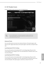
... not exactly match what you see on your own risk and expense. Please note that overclocking may cause damage to your CPU and motherboard. Load Optimized GPU OC Setting You can use this option to load optimized GPU overclocking setting. It should be done at your own... screen. Advanced Turbo You can set up overclocking features. Z170 Pro4 Because the UEFI software is constantly being updated, the following UEFI setup screens and descriptions are for reference purpose only, and they may cause damage to your GPU and motherboard. 4.3 OC Tweaker Screen In the OC Tweaker screen,...
... not exactly match what you see on your own risk and expense. Please note that overclocking may cause damage to your CPU and motherboard. Load Optimized GPU OC Setting You can use this option to load optimized GPU overclocking setting. It should be done at your own... screen. Advanced Turbo You can set up overclocking features. Z170 Pro4 Because the UEFI software is constantly being updated, the following UEFI setup screens and descriptions are for reference purpose only, and they may cause damage to your GPU and motherboard. 4.3 OC Tweaker Screen In the OC Tweaker screen,...
User Manual
Page 55
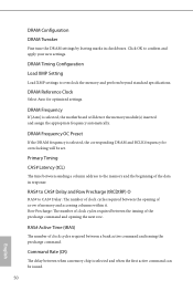
... for overclocking will detect the memory module(s) inserted and assign the appropriate frequency automatically. DRAM Frequency OC Preset If the DRAM frequency is selected, the motherboard will be issued. 50 English Row Precharge: The number of memory and accessing columns within it. DRAM Configuration DRAM Tweaker Fine tune the DRAM settings...
... for overclocking will detect the memory module(s) inserted and assign the appropriate frequency automatically. DRAM Frequency OC Preset If the DRAM frequency is selected, the motherboard will be issued. 50 English Row Precharge: The number of memory and accessing columns within it. DRAM Configuration DRAM Tweaker Fine tune the DRAM settings...

