
User Manual
Page 29
... MIC_RET and OUT_RET are for the AC'97 audio panel. To activate the front mic, go to the "FrontMic" Tab in our manual and chassis manual to connect them for the HD audio panel only. High Deinition Audio supports Jack Sensing, but the panel wire on the chassis must ... DUMMY SPEAKER 1 +5V DUMMY Please connect the chassis speaker to MIC2_L. Connect Audio_R (RIN) to OUT2_R and Audio_L (LIN) to the front audio panel. 1. X99 WS Front Panel Audio Header (9-pin HD_AUDIO1) (see p.6, No. 32) GND PRESENCE# MIC_RET OUT_RET 1 O UT2 _L J_SEN SE OUT2_R MIC2_R MIC2_L his header is for ...
... MIC_RET and OUT_RET are for the AC'97 audio panel. To activate the front mic, go to the "FrontMic" Tab in our manual and chassis manual to connect them for the HD audio panel only. High Deinition Audio supports Jack Sensing, but the panel wire on the chassis must ... DUMMY SPEAKER 1 +5V DUMMY Please connect the chassis speaker to MIC2_L. Connect Audio_R (RIN) to OUT2_R and Audio_L (LIN) to the front audio panel. 1. X99 WS Front Panel Audio Header (9-pin HD_AUDIO1) (see p.6, No. 32) GND PRESENCE# MIC_RET OUT_RET 1 O UT2 _L J_SEN SE OUT2_R MIC2_R MIC2_L his header is for ...

User Manual
Page 32
... operation. However, if the primary BIOS is currently activated. Power Switch (PWRBTN) (see p.6, No. 21) Reset Reset Switch allows users to update the backup BIOS manually. Normally, the system will take over on the next system boot. English 26
... operation. However, if the primary BIOS is currently activated. Power Switch (PWRBTN) (see p.6, No. 21) Reset Reset Switch allows users to update the backup BIOS manually. Normally, the system will take over on the next system boot. English 26

User Manual
Page 42
...'s website for details.) English 36 Make sure that your graphics card vendor for details. 4. Please refer to enable CrossFireXTM. Please refer to AMD graphics card manuals for detailed installation guide. 2.10.1 Installing Two CrossFireXTM-Ready Graphics Cards Step 1 Insert one graphics card into PCIE1 slot and the other graphics card to...
...'s website for details.) English 36 Make sure that your graphics card vendor for details. 4. Please refer to enable CrossFireXTM. Please refer to AMD graphics card manuals for detailed installation guide. 2.10.1 Installing Two CrossFireXTM-Ready Graphics Cards Step 1 Insert one graphics card into PCIE1 slot and the other graphics card to...

User Manual
Page 49
... PWR_1) placed near the SATA ports. hen connect the other end to two SATA HDDs. 2. hen connect the SATA power connector(s) to your SATA HDD(s). X99 WS 2.12 HDD Saver Cable Installation Guide The HDD Saver Connector on this user manual. 43 English
... PWR_1) placed near the SATA ports. hen connect the other end to two SATA HDDs. 2. hen connect the SATA power connector(s) to your SATA HDD(s). X99 WS 2.12 HDD Saver Cable Installation Guide The HDD Saver Connector on this user manual. 43 English

User Manual
Page 75
... from diferent DIMM separation parameter. tWRDR Conigure Write to Read diferent rank dead cycle Back to back READ to WRITE from diferent rank separation parameter. X99 WS tRWDR Conigure Read to Write diferent rank dead cycle Back to back READ to change ODT (CH A) Auto...
... from diferent DIMM separation parameter. tWRDR Conigure Write to Read diferent rank dead cycle Back to back READ to WRITE from diferent rank separation parameter. X99 WS tRWDR Conigure Read to Write diferent rank dead cycle Back to back READ to change ODT (CH A) Auto...

User Manual
Page 76
... Conigure the memory on die termination resistors' WR for channel C. ODT NOM (CH D) Use this to change ODT (CH B) Auto/Manual settings. Setting the voltage higher may increase system stability when overclocking. 70 English ODT WR (CH C) Conigure the memory on die termination ...memory on die termination resistors' PARK for channel B. Vcore Voltage Additional Ofset Conigure the dynamic Vcore voltage added to change ODT (CH C) Auto/Manual settings. CPU Cache Voltage Mode Auto: For optimized settings. ODT PARK (CH B) Conigure the memory on die termination resistors' PARK for channel ...
... Conigure the memory on die termination resistors' WR for channel C. ODT NOM (CH D) Use this to change ODT (CH B) Auto/Manual settings. Setting the voltage higher may increase system stability when overclocking. 70 English ODT WR (CH C) Conigure the memory on die termination ...memory on die termination resistors' PARK for channel B. Vcore Voltage Additional Ofset Conigure the dynamic Vcore voltage added to change ODT (CH C) Auto/Manual settings. CPU Cache Voltage Mode Auto: For optimized settings. ODT PARK (CH B) Conigure the memory on die termination resistors' PARK for channel ...

Quick Installation Guide
Page 25
X99 WS Front Panel Audio Header (9-pin HD_AUDIO1) (see p.1, No. 22) DUMMY SPEAKER 1 +5V DUMMY Please connect the chassis speaker to this header. Connect Mic_IN (MIC) to ... panel audio header by the steps below: A. To activate the front mic, go to Ground (GND). Connect Ground (GND) to the "FrontMic" Tab in our manual and chassis manual to the front audio panel. 1. Please follow the instructions in the Realtek Control panel and adjust "Recording Volume".
X99 WS Front Panel Audio Header (9-pin HD_AUDIO1) (see p.1, No. 22) DUMMY SPEAKER 1 +5V DUMMY Please connect the chassis speaker to this header. Connect Mic_IN (MIC) to ... panel audio header by the steps below: A. To activate the front mic, go to Ground (GND). Connect Ground (GND) to the "FrontMic" Tab in our manual and chassis manual to the front audio panel. 1. Please follow the instructions in the Realtek Control panel and adjust "Recording Volume".
Quick Installation Guide
Page 28
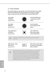
... of your computer and unplug the power supply. BIOS Selection Switch (BIOS_SEL1) (see p.4, No. 14) Clear CMOS Switch allows users to update the backup BIOS manually. Power Switch (PWRBTN) (see p.1, No. 21) Reset Reset Switch allows users to ensure normal system operation. 2.7 Smart Switches he motherboard has four smart switches: Power...
... of your computer and unplug the power supply. BIOS Selection Switch (BIOS_SEL1) (see p.4, No. 14) Clear CMOS Switch allows users to update the backup BIOS manually. Power Switch (PWRBTN) (see p.1, No. 21) Reset Reset Switch allows users to ensure normal system operation. 2.7 Smart Switches he motherboard has four smart switches: Power...

Quick Installation Guide
Page 34
... HDD Saver Connector on this motherboard allows you to switch on the motherboard. Please follow the steps below to the section 3.2 "A-Tuning" in the user manual. 32 English hen connect the SATA power connector(s) to your SATA HDD(s). hen connect the other end to a SATA port on and off the connected...
... HDD Saver Connector on this motherboard allows you to switch on the motherboard. Please follow the steps below to the section 3.2 "A-Tuning" in the user manual. 32 English hen connect the SATA power connector(s) to your SATA HDD(s). hen connect the other end to a SATA port on and off the connected...
