RAID Installation Guide
Page 2
1. You may install SATA hard disks on SATA ports. 2 This section will guide you how to SATA Hard Disks Installation 1.1 Serial ATA (SATA) Hard Disks Installation Intel chipset supports Serial ATA (SATA) hard disks with RAID functions, including RAID 0, RAID 1, RAID 5, RAID 10 and Intel Rapid Storage. Please read the RAID conigurations in this motherboard for internal storage devices. Guide to create RAID on this guide carefully according to the Intel southbridge chipset that your motherboard adopts.
1. You may install SATA hard disks on SATA ports. 2 This section will guide you how to SATA Hard Disks Installation 1.1 Serial ATA (SATA) Hard Disks Installation Intel chipset supports Serial ATA (SATA) hard disks with RAID functions, including RAID 0, RAID 1, RAID 5, RAID 10 and Intel Rapid Storage. Please read the RAID conigurations in this motherboard for internal storage devices. Guide to create RAID on this guide carefully according to the Intel southbridge chipset that your motherboard adopts.
RAID Installation Guide
Page 3
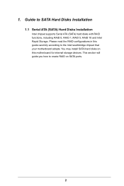
... one drive fails. 3 It provides data protection and increases fault tolerance to the entire system since it will introduce the basic knowledge of RAID This motherboard adopts Intel southbridge chipset that optimizes two identical hard disk drives to RAID Conigurations 2.1 Introduction of RAID, and the guide to the surviving drive as...
... one drive fails. 3 It provides data protection and increases fault tolerance to the entire system since it will introduce the basic knowledge of RAID This motherboard adopts Intel southbridge chipset that optimizes two identical hard disk drives to RAID Conigurations 2.1 Introduction of RAID, and the guide to the surviving drive as...
RAID Installation Guide
Page 18
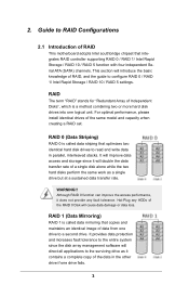
STEP 1: Copy Intel® RAID drivers into a USB lash disk You can download the drivers from ASRock's website and unzip the iles into a USB lash disk or copy the iles from ASRock's motherboard support CD. (Please copy the iles under the following directory: 32 bit: ..\i386\Win7_Intel.. 64-bit: ..\AMD64\Win7-64_Intel.. 4. STEP 2: Install...
STEP 1: Copy Intel® RAID drivers into a USB lash disk You can download the drivers from ASRock's website and unzip the iles into a USB lash disk or copy the iles from ASRock's motherboard support CD. (Please copy the iles under the following directory: 32 bit: ..\i386\Win7_Intel.. 64-bit: ..\AMD64\Win7-64_Intel.. 4. STEP 2: Install...
RAID Installation Guide
Page 20
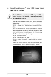
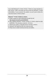
... / 8 64-bit / 8.1 64-bit, install the hotix kb2505454. (This may take about 5 minutes to reboot.) D. Reboot your system. (It may take more time to install motherboard drivers and utilities. 20 Windows® 7 64-bit / 8 64-bit / 8.1 64-bit: A. If you encounter this problem, you install Windows® 8.1 64-bit / 8 64-bit...
... / 8 64-bit / 8.1 64-bit, install the hotix kb2505454. (This may take about 5 minutes to reboot.) D. Reboot your system. (It may take more time to install motherboard drivers and utilities. 20 Windows® 7 64-bit / 8 64-bit / 8.1 64-bit: A. If you encounter this problem, you install Windows® 8.1 64-bit / 8 64-bit...

User Manual
Page 2
... not provide warranty of any errors or omissions that may appear in this motherboard contains Perchlorate, a toxic substance controlled in advance. With respect to the contents of this documentation. ASRock assumes no event shall ASRock, its directors, oicers, employees, or agents be liable for any indirect, special, incidental, or consequential damages (including damages...
... not provide warranty of any errors or omissions that may appear in this motherboard contains Perchlorate, a toxic substance controlled in advance. With respect to the contents of this documentation. ASRock assumes no event shall ASRock, its directors, oicers, employees, or agents be liable for any indirect, special, incidental, or consequential damages (including damages...

User Manual
Page 4
Contents Chapter 1 Introduction 1 1.1 Package Contents 1 1.2 Speciications 2 1.3 Motherboard Layout 6 1.4 I/O Panel 9 Chapter 2 Installation 11 2.1 Installing the CPU 12 2.2 Installing the CPU Fan and Heatsink 15 2.3 Installation of Memory Modules (DIMM) 16 2.4 Expansion Slots (PCI ...
Contents Chapter 1 Introduction 1 1.1 Package Contents 1 1.2 Speciications 2 1.3 Motherboard Layout 6 1.4 I/O Panel 9 Chapter 2 Installation 11 2.1 Installing the CPU 12 2.2 Installing the CPU Fan and Heatsink 15 2.3 Installation of Memory Modules (DIMM) 16 2.4 Expansion Slots (PCI ...

User Manual
Page 7
... http://www.asrock.com. 1.1 Package Contents • ASRock X99 WS Motherboard (EATX Form Factor) • ASRock X99 WS Quick Installation Guide • ASRock X99 WS Support CD • 1 x I/O Panel Shield • 2 x ASRock SLI_Bridge Cards • 1 x ASRock SLI_Bridge_3S Card • 1 x ASRock 3-Way SLI Bridge Card • 4 x Serial ATA (SATA) Data Cables (Optional) • 1 x HDD Saver Cable • 1 x Screw for purchasing ASRock X99 WS motherboard, a reliable motherboard produced under ASRock's consistently stringent...
... http://www.asrock.com. 1.1 Package Contents • ASRock X99 WS Motherboard (EATX Form Factor) • ASRock X99 WS Quick Installation Guide • ASRock X99 WS Support CD • 1 x I/O Panel Shield • 2 x ASRock SLI_Bridge Cards • 1 x ASRock SLI_Bridge_3S Card • 1 x ASRock 3-Way SLI Bridge Card • 4 x Serial ATA (SATA) Data Cables (Optional) • 1 x HDD Saver Cable • 1 x Screw for purchasing ASRock X99 WS motherboard, a reliable motherboard produced under ASRock's consistently stringent...

User Manual
Page 12
1.3 Motherboard Layout USB 2.0 T: USB1 B: USB2 PS2 Keyboard /Mouse CLRC BTN1 USB 2.0 T: USB3 B: USB4 ATX12V1 2011-3 Socket CPU_FAN1 CPU_FAN2 ATXPWR1 DDR4_D2 (64 bit, 284-pin module)...Gen3 x4 CT5 CT4 CT3 CT2 CT1 M2_1 CMOS Battery SATA_PWR_1 1 S_SATA3_2_3 S_SATA3_0_1 PCIE2 Purity SoundTM 2 HD_AUDIO1 1 PCIE_PWR2 1 TBT1 COM1 1 PCIE3 X99 WS PCIE4 PCIE5 RoHS PCIE6 COM2 1 USB5_6 1 USB7_8 1 SATA3_4_5 Intel X99 SATA3_2_3 SATA3_0_1 Super I/O TPMS1 1 CHA_FAN1 CHA_FAN2 CLRMOS1 1 Reset BIOS_A_LED BIOS_B_LED 128Mb BIOS BIOS_A SPEAKER1 1 PLED1 1 A B BIOS_SEL1 128Mb BIOS ...
1.3 Motherboard Layout USB 2.0 T: USB1 B: USB2 PS2 Keyboard /Mouse CLRC BTN1 USB 2.0 T: USB3 B: USB4 ATX12V1 2011-3 Socket CPU_FAN1 CPU_FAN2 ATXPWR1 DDR4_D2 (64 bit, 284-pin module)...Gen3 x4 CT5 CT4 CT3 CT2 CT1 M2_1 CMOS Battery SATA_PWR_1 1 S_SATA3_2_3 S_SATA3_0_1 PCIE2 Purity SoundTM 2 HD_AUDIO1 1 PCIE_PWR2 1 TBT1 COM1 1 PCIE3 X99 WS PCIE4 PCIE5 RoHS PCIE6 COM2 1 USB5_6 1 USB7_8 1 SATA3_4_5 Intel X99 SATA3_2_3 SATA3_0_1 Super I/O TPMS1 1 CHA_FAN1 CHA_FAN2 CLRMOS1 1 Reset BIOS_A_LED BIOS_B_LED 128Mb BIOS BIOS_A SPEAKER1 1 PLED1 1 A B BIOS_SEL1 128Mb BIOS ...

User Manual
Page 17
... cause physical injuries and damages to motherboard components. • In order to avoid damage from static electricity to the motherboard's components, NEVER place your chassis to the chassis, please do so may damage the motherboard. 11 English X99 WS Chapter 2 Installation his is an EATX form factor motherboard. Before you install motherboard components or change any components...
... cause physical injuries and damages to motherboard components. • In order to avoid damage from static electricity to the motherboard's components, NEVER place your chassis to the chassis, please do so may damage the motherboard. 11 English X99 WS Chapter 2 Installation his is an EATX form factor motherboard. Before you install motherboard components or change any components...

User Manual
Page 20
6 7 A B 8 A B English Please save and replace the cover if the processor is removed. he cover must be placed if you wish to return the motherboard for ater service. 14
6 7 A B 8 A B English Please save and replace the cover if the processor is removed. he cover must be placed if you wish to return the motherboard for ater service. 14

User Manual
Page 22
...priority. he DIMM only its in the DDR4 DIMM slots, then Dual Channel Memory Technology is activated. It will cause permanent damage to the motherboard and the DIMM if you want to use more than four memory modules, please install the other memory modules from let to right (from DDR4_A2...Technology is not allowed to DDR4_C2.) • If only two memory modules are installed in one correct orientation. 2.3 Installation of Memory Modules (DIMM) his motherboard provides eight 284-pin DDR4 (Double Data Rate 4) DIMM slots, and supports Quad Channel Memory Technology. 1. otherwise, this...
...priority. he DIMM only its in the DDR4 DIMM slots, then Dual Channel Memory Technology is activated. It will cause permanent damage to the motherboard and the DIMM if you want to use more than four memory modules, please install the other memory modules from let to right (from DDR4_A2...Technology is not allowed to DDR4_C2.) • If only two memory modules are installed in one correct orientation. 2.3 Installation of Memory Modules (DIMM) his motherboard provides eight 284-pin DDR4 (Double Data Rate 4) DIMM slots, and supports Quad Channel Memory Technology. 1. otherwise, this...

User Manual
Page 24
... (PCIe 2.0 x16 slot) is used for the card before you start the installation. 2.4 Expansion Slots (PCI Express Slots) here are 6 PCI Express slots on the motherboard. PCIE2 (PCIe 3.0 x16 slot) is unplugged. Please read the documentation of the expansion card and make sure that the power supply is switched of or...
... (PCIe 2.0 x16 slot) is used for the card before you start the installation. 2.4 Expansion Slots (PCI Express Slots) here are 6 PCI Express slots on the motherboard. PCIE2 (PCIe 3.0 x16 slot) is unplugged. Please read the documentation of the expansion card and make sure that the power supply is switched of or...

User Manual
Page 25
For a better thermal environment, please connect a chassis fan to the motherboard's chassis fan connector (CHA_FAN1, CHA_FAN2 or CHA_FAN3) when using multiple graphics cards. English 19 X99 WS PCIe Slot Conigurations (For CPU with 28 PCIe lanes) PCIE1 PCIE2 PCIE3 PCIE4 PCIE5 PCIE6 Single Graphics Card x16 N/A N/A N/A N/A N/A Two Graphics Cards in CrossFireXTM or ...
For a better thermal environment, please connect a chassis fan to the motherboard's chassis fan connector (CHA_FAN1, CHA_FAN2 or CHA_FAN3) when using multiple graphics cards. English 19 X99 WS PCIe Slot Conigurations (For CPU with 28 PCIe lanes) PCIE1 PCIE2 PCIE3 PCIE4 PCIE5 PCIE6 Single Graphics Card x16 N/A N/A N/A N/A N/A Two Graphics Cards in CrossFireXTM or ...

User Manual
Page 27
... mainly consists of your chassis front panel module to turn of power switch, reset switch, power LED, hard drive activity LED, speaker and etc. X99 WS 2.6 Onboard Headers and Connectors Onboard headers and connectors are matched correctly. System Panel Header (9-pin PANEL1) (see p.6, No. 18) PLED+ PLEDPWRBTN#...to perform a normal restart. English 21 Do NOT place jumper caps over the headers and connectors will cause permanent damage to the motherboard. he LED is on the chassis front panel. Press the reset switch to restart the computer if the computer freezes and fails ...
... mainly consists of your chassis front panel module to turn of power switch, reset switch, power LED, hard drive activity LED, speaker and etc. X99 WS 2.6 Onboard Headers and Connectors Onboard headers and connectors are matched correctly. System Panel Header (9-pin PANEL1) (see p.6, No. 18) PLED+ PLEDPWRBTN#...to perform a normal restart. English 21 Do NOT place jumper caps over the headers and connectors will cause permanent damage to the motherboard. he LED is on the chassis front panel. Press the reset switch to restart the computer if the computer freezes and fails ...

User Manual
Page 28
... the I /O has been connected, the internal S_SATA3_3 will not function. * RAID is supported on the rear I /O panel, there is one header on this motherboard. Power LED Header (3-pin PLED1) (see p.6, No. 19) Serial ATA3 Connectors (S_SATA3_0_1: see p.6, No. 12) (S_SATA3_2_3: see p.6, No. 13) (SATA3_0_1...9) 22 USB_PWR PP+ GND DUMMY 1 GND P+ PUSB_PWR Besides four USB 2.0 ports on the I/O panel, there are two headers on this motherboard. hese ten SATA3 connectors support SATA data cables for internal storage devices with up to indicate the system's power status. If the Ultra M.2 ...
... the I /O has been connected, the internal S_SATA3_3 will not function. * RAID is supported on the rear I /O panel, there is one header on this motherboard. Power LED Header (3-pin PLED1) (see p.6, No. 19) Serial ATA3 Connectors (S_SATA3_0_1: see p.6, No. 12) (S_SATA3_2_3: see p.6, No. 13) (SATA3_0_1...9) 22 USB_PWR PP+ GND DUMMY 1 GND P+ PUSB_PWR Besides four USB 2.0 ports on the I/O panel, there are two headers on this motherboard. hese ten SATA3 connectors support SATA data cables for internal storage devices with up to indicate the system's power status. If the Ultra M.2 ...

User Manual
Page 30
...1 and Pin 5. PCIe Power Connectors (4-pin PCIE_PWR1) (see p.6, No. 34) (4-pin PCIE_PWR2) (see p.6, No. 8) 12 24 1 13 his motherboard provides a 24-pin ATX power connector. To use a 4-pin ATX power supply, please plug it along Pin 1 and Pin 13. English CPU Fan ...Connectors (4-pin CPU_FAN1) (see p.6, No. 6) (3-pin CPU_FAN2) (see p.6, No. 7) 4 3 21 CPU_FAN_SPEED FAN_SPEED_CONTROL GND FAN_VOLTAGE FAN_SPEED his motherboard provides an 8-pin ATX 12V power connector. If you plan to manage the power state of HDD. ATX Power Connector (24-pin ATXPWR1) (see p.6, ...
...1 and Pin 5. PCIe Power Connectors (4-pin PCIE_PWR1) (see p.6, No. 34) (4-pin PCIE_PWR2) (see p.6, No. 8) 12 24 1 13 his motherboard provides a 24-pin ATX power connector. To use a 4-pin ATX power supply, please plug it along Pin 1 and Pin 13. English CPU Fan ...Connectors (4-pin CPU_FAN1) (see p.6, No. 6) (3-pin CPU_FAN2) (see p.6, No. 7) 4 3 21 CPU_FAN_SPEED FAN_SPEED_CONTROL GND FAN_VOLTAGE FAN_SPEED his motherboard provides an 8-pin ATX 12V power connector. If you plan to manage the power state of HDD. ATX Power Connector (24-pin ATXPWR1) (see p.6, ...

User Manual
Page 32
... smart switches: Power Switch, Reset Switch, Clear CMOS Switch and one BIOS Selection Switch, allowing users to quickly turn on the next system boot. his motherboard has two BIOS chips, a primary BIOS (BIOS_A) and a backup BIOS (BIOS_B), which BIOS is corrupted or damaged, just lip the BIOS Selection Switch to "B", then...
... smart switches: Power Switch, Reset Switch, Clear CMOS Switch and one BIOS Selection Switch, allowing users to quickly turn on the next system boot. his motherboard has two BIOS chips, a primary BIOS (BIOS_A) and a backup BIOS (BIOS_B), which BIOS is corrupted or damaged, just lip the BIOS Selection Switch to "B", then...

User Manual
Page 35
... minimum power your graphics card driver supports NVIDIA® SLITM technology. Make sure that are properly seated on the slots. X99 WS 2.9 SLITM , 3-Way SLITM , 4-Way SLITM and Quad SLITM Operation Guide his motherboard supports NVIDIA® SLITM , 3-way SLITM, 4-way SLITM and Quad SLITM (Scalable Link Interface) technology that allows you to...
... minimum power your graphics card driver supports NVIDIA® SLITM technology. Make sure that are properly seated on the slots. X99 WS 2.9 SLITM , 3-Way SLITM , 4-Way SLITM and Quad SLITM Operation Guide his motherboard supports NVIDIA® SLITM , 3-way SLITM, 4-way SLITM and Quad SLITM (Scalable Link Interface) technology that allows you to...

User Manual
Page 42
.... (he CrossFire Bridge is recommended to the AMD's website for details.) English 36 2.10 CrossFireXTM, 3-Way CrossFireXTM, 4-Way CrossFireXTM and Quad CrossFireXTM Operation Guide his motherboard supports CrossFireXTM, 3-way CrossFireXTM, 4-way CrossFireXTM and Quad CrossFireXTM that allows you purchase, not bundled with this...
.... (he CrossFire Bridge is recommended to the AMD's website for details.) English 36 2.10 CrossFireXTM, 3-Way CrossFireXTM, 4-Way CrossFireXTM and Quad CrossFireXTM Operation Guide his motherboard supports CrossFireXTM, 3-way CrossFireXTM, 4-way CrossFireXTM and Quad CrossFireXTM that allows you purchase, not bundled with this...

User Manual
Page 43
English 37 X99 WS Step 3 Connect a VGA cable or a DVI cable to the monitor connector or the DVI connector of the graphics card that is provided with the graphics card you purchase, not bundled with this motherboard. Please refer to your graphics card vendor for details.) Step 3 Connect a VGA cable or a DVI cable to...
English 37 X99 WS Step 3 Connect a VGA cable or a DVI cable to the monitor connector or the DVI connector of the graphics card that is provided with the graphics card you purchase, not bundled with this motherboard. Please refer to your graphics card vendor for details.) Step 3 Connect a VGA cable or a DVI cable to...


