
User Manual
Page 29
... for the HD audio panel only. E. To activate the front mic, go to the "FrontMic" Tab in our manual and chassis manual to MIC2_L. CHA_ FAN fan speed can be controlled through UEFI or A-Tuning. X99 WS Front Panel Audio Header (9-pin HD_AUDIO1) (see p.6, No. 32) GND PRESENCE# MIC_RET OUT_RET 1 O UT2 _L J_SEN SE...
... for the HD audio panel only. E. To activate the front mic, go to the "FrontMic" Tab in our manual and chassis manual to MIC2_L. CHA_ FAN fan speed can be controlled through UEFI or A-Tuning. X99 WS Front Panel Audio Header (9-pin HD_AUDIO1) (see p.6, No. 32) GND PRESENCE# MIC_RET OUT_RET 1 O UT2 _L J_SEN SE...

User Manual
Page 32
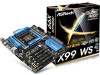
... he motherboard has four smart switches: Power Switch, Reset Switch, Clear CMOS Switch and one BIOS Selection Switch, allowing users to update the backup BIOS manually. Reset Switch (RSTBTN) (see p.6, No. 20) Power Power Switch allows users to "B", then the backup BIOS will work on /of the system...
... he motherboard has four smart switches: Power Switch, Reset Switch, Clear CMOS Switch and one BIOS Selection Switch, allowing users to update the backup BIOS manually. Reset Switch (RSTBTN) (see p.6, No. 20) Power Power Switch allows users to "B", then the backup BIOS will work on /of the system...

User Manual
Page 42
... is recommended to your graphics card vendor for details. 4. Diferent CrossFireXTM cards may require diferent methods to PCIE4 slot. Please refer to AMD graphics card manuals for detailed installation guide. 2.10.1 Installing Two CrossFireXTM-Ready Graphics Cards Step 1 Insert one graphics card into PCIE1 slot and the other graphics card to...
... is recommended to your graphics card vendor for details. 4. Diferent CrossFireXTM cards may require diferent methods to PCIE4 slot. Please refer to AMD graphics card manuals for detailed installation guide. 2.10.1 Installing Two CrossFireXTM-Ready Graphics Cards Step 1 Insert one graphics card into PCIE1 slot and the other graphics card to...

User Manual
Page 49
... HDDs via sotware when needed. Please follow the steps below to your SATA HDD(s). * he diagram shown here is for reference only. 1. X99 WS 2.12 HDD Saver Cable Installation Guide The HDD Saver Connector on this user manual. 43 English his design secures more privacy, saves more energy, and extends the HDDs' lifespans.
... HDDs via sotware when needed. Please follow the steps below to your SATA HDD(s). * he diagram shown here is for reference only. 1. X99 WS 2.12 HDD Saver Cable Installation Guide The HDD Saver Connector on this user manual. 43 English his design secures more privacy, saves more energy, and extends the HDDs' lifespans.

User Manual
Page 75
...Conigure Write to Read diferent DIMM dead cycle Back to back READ to WRITE from diferent DIMM separation parameter. he default is [Auto]. X99 WS tRWDR Conigure Read to Write diferent rank dead cycle Back to back READ to WRITE from diferent DIMM separation parameter. tRRDR Conigure Read to...termination resistors' WR for channel A. tWRDR Conigure Write to Read diferent rank dead cycle Back to back READ to change ODT (CH A) Auto/Manual settings. ODT NOM (CH A) Use this to WRITE from diferent rank separation parameter. tWWDR Conigure Write to Write diferent rank dead cycle Back to...
...Conigure Write to Read diferent DIMM dead cycle Back to back READ to WRITE from diferent DIMM separation parameter. he default is [Auto]. X99 WS tRWDR Conigure Read to Write diferent rank dead cycle Back to back READ to WRITE from diferent DIMM separation parameter. tRRDR Conigure Read to...termination resistors' WR for channel A. tWRDR Conigure Write to Read diferent rank dead cycle Back to back READ to change ODT (CH A) Auto/Manual settings. ODT NOM (CH A) Use this to WRITE from diferent rank separation parameter. tWWDR Conigure Write to Write diferent rank dead cycle Back to...

User Manual
Page 76
...Setting the voltage higher may increase system stability when overclocking. 70 English ODT NOM (CH D) Use this to change ODT (CH B) Auto/Manual settings. Vcore Voltage Additional Ofset Conigure the dynamic Vcore voltage added to the CPU Cache when the system is ixed. CPU Cache Voltage Mode ...die termination resistors' PARK for channel C. ODT NOM (CH B) Use this to change ODT (CH D) Auto/Manual settings. ODT NOM (CH C) Use this to change ODT (CH C) Auto/Manual settings. CPU Cache Voltage Ofset Conigure the voltage for channel C. FIVR Coniguration CPU Vcore Voltage Mode Auto: For ...
...Setting the voltage higher may increase system stability when overclocking. 70 English ODT NOM (CH D) Use this to change ODT (CH B) Auto/Manual settings. Vcore Voltage Additional Ofset Conigure the dynamic Vcore voltage added to the CPU Cache when the system is ixed. CPU Cache Voltage Mode ...die termination resistors' PARK for channel C. ODT NOM (CH B) Use this to change ODT (CH D) Auto/Manual settings. ODT NOM (CH C) Use this to change ODT (CH C) Auto/Manual settings. CPU Cache Voltage Ofset Conigure the voltage for channel C. FIVR Coniguration CPU Vcore Voltage Mode Auto: For ...

Quick Installation Guide
Page 25
... (GND). CHA_ FAN fan speed can be controlled through UEFI or A-Tuning. Connect Ground (GND) to the "FrontMic" Tab in our manual and chassis manual to install your system. 2. D. GND FAN_VOLTAGE FAN_SPEED GND +12V FAN_SPEED 23 English C. You don't need to function correctly. High Deinition Audio...the AC'97 audio panel. MIC_RET and OUT_RET are for the HD audio panel only. Connect Mic_IN (MIC) to the front audio panel. 1. X99 WS Front Panel Audio Header (9-pin HD_AUDIO1) (see p.1, No. 32) GND PRESENCE# MIC_RET OUT_RET 1 OUT2_L J_SENSE OUT2_R MIC2_R MIC2_L his header is...
... (GND). CHA_ FAN fan speed can be controlled through UEFI or A-Tuning. Connect Ground (GND) to the "FrontMic" Tab in our manual and chassis manual to install your system. 2. D. GND FAN_VOLTAGE FAN_SPEED GND +12V FAN_SPEED 23 English C. You don't need to function correctly. High Deinition Audio...the AC'97 audio panel. MIC_RET and OUT_RET are for the HD audio panel only. Connect Mic_IN (MIC) to the front audio panel. 1. X99 WS Front Panel Audio Header (9-pin HD_AUDIO1) (see p.1, No. 32) GND PRESENCE# MIC_RET OUT_RET 1 OUT2_L J_SENSE OUT2_R MIC2_R MIC2_L his header is...
Quick Installation Guide
Page 28
... chips, a primary BIOS (BIOS_A) and a backup BIOS (BIOS_B), which BIOS is corrupted or damaged, just lip the BIOS Selection Switch to update the backup BIOS manually. BIOS Selection Switch (BIOS_SEL1) (see p.1, No. 20) Power Power Switch allows users to ensure normal system operation. However, if the primary BIOS is currently activated...
... chips, a primary BIOS (BIOS_A) and a backup BIOS (BIOS_B), which BIOS is corrupted or damaged, just lip the BIOS Selection Switch to update the backup BIOS manually. BIOS Selection Switch (BIOS_SEL1) (see p.1, No. 20) Power Power Switch allows users to ensure normal system operation. However, if the primary BIOS is currently activated...

Quick Installation Guide
Page 34
... needed. Connect one end of the SATA data cable to two SATA HDDs. 2. Please follow the steps below to the section 3.2 "A-Tuning" in the user manual. 32 English
... needed. Connect one end of the SATA data cable to two SATA HDDs. 2. Please follow the steps below to the section 3.2 "A-Tuning" in the user manual. 32 English
