RAID Installation Guide
Page 1
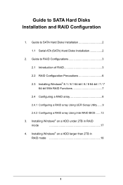
...; 8.1 / 8.1 64-bit / 8 / 8 64-bit / 7 / 7 64-bit With RAID Functions 7 2.4 Coniguring a RAID array 8 2.4.1 Coniguring a RAID array Using UEFI Setup Utility ...... 9 2.4.2 Coniguring a RAID array Using Intel RAID BIOS ...... 13 3. Guide to SATA Hard Disks Installation 2 1.1 Serial ATA (SATA) Hard Disks Installation 2 2. Guide to SATA Hard Disks Installation and RAID Coniguration 1.
...; 8.1 / 8.1 64-bit / 8 / 8 64-bit / 7 / 7 64-bit With RAID Functions 7 2.4 Coniguring a RAID array 8 2.4.1 Coniguring a RAID array Using UEFI Setup Utility ...... 9 2.4.2 Coniguring a RAID array Using Intel RAID BIOS ...... 13 3. Guide to SATA Hard Disks Installation 2 1.1 Serial ATA (SATA) Hard Disks Installation 2 2. Guide to SATA Hard Disks Installation and RAID Coniguration 1.
RAID Installation Guide
Page 7
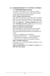
STEP 1: Setting the BIOS RAID Items After installing the hard disk drives, please set the necessary RAID items in UEFI setup. STEP 2: Use ASRock Easy RAID Installer Easy RAID Installer can copy the RAID driver from a support CD to your USB storage device with RAID functions, ...; 8.1 / 8.1 64-bit /8 / 8 64-bit / 7 / 7 64-bit OS on your SATA / SATA2 / SATA3 HDDs with just one simple click in the BIOS before you exit BIOS setup. Go to Advanced Storage Coniguration and set RAID coniguration. A. Follow the onscreen instruction to set the option SATA Mode Selection to conirm the...
STEP 1: Setting the BIOS RAID Items After installing the hard disk drives, please set the necessary RAID items in UEFI setup. STEP 2: Use ASRock Easy RAID Installer Easy RAID Installer can copy the RAID driver from a support CD to your USB storage device with RAID functions, ...; 8.1 / 8.1 64-bit /8 / 8 64-bit / 7 / 7 64-bit OS on your SATA / SATA2 / SATA3 HDDs with just one simple click in the BIOS before you exit BIOS setup. Go to Advanced Storage Coniguration and set RAID coniguration. A. Follow the onscreen instruction to set the option SATA Mode Selection to conirm the...
RAID Installation Guide
Page 8
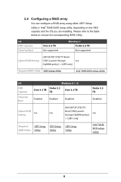
2.4 Coniguring a RAID array You can conigure a RAID array using either UEFI Setup Utility or Intel® RAID BIOS setup utility, depending on the HDD capacity and the OS you are installing. OS HDD Capacity Ultra Fast Boot Over 2.2 TB Not supported ... supported Option ROM Setting UEFI SETUP UTILITY\Boot\ CSM [Launch Storage n/a OpROM policy] = [UEFI only] Required RAID Utility UEFI Setup Utility Intel® RAID BIOS setup utility OS HDD Capacity Ultra Fast Boot Windows 8.1 / 8 Under 2.2 Over 2.2 TB Over 2.2 TB TB Enabled Enabled Disabled Under 2.2 TB Disabled UEFI SETUP...
2.4 Coniguring a RAID array You can conigure a RAID array using either UEFI Setup Utility or Intel® RAID BIOS setup utility, depending on the HDD capacity and the OS you are installing. OS HDD Capacity Ultra Fast Boot Over 2.2 TB Not supported ... supported Option ROM Setting UEFI SETUP UTILITY\Boot\ CSM [Launch Storage n/a OpROM policy] = [UEFI only] Required RAID Utility UEFI Setup Utility Intel® RAID BIOS setup utility OS HDD Capacity Ultra Fast Boot Windows 8.1 / 8 Under 2.2 Over 2.2 TB Over 2.2 TB TB Enabled Enabled Disabled Under 2.2 TB Disabled UEFI SETUP...
RAID Installation Guide
Page 13
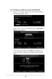
Create RAID Volume window appears. Volume0 13 Then, the Intel RAID Utility - 2.4.2 Coniguring a RAID array Using Intel RAID BIOS Reboot your RAID volume then press . Press . In the Create Volume Menu, under Name item, please key-in a unique name with 1-16 letters for your computer. Wait until you see the RAID software prompting you to press .
Create RAID Volume window appears. Volume0 13 Then, the Intel RAID Utility - 2.4.2 Coniguring a RAID array Using Intel RAID BIOS Reboot your RAID volume then press . Press . In the Create Volume Menu, under Name item, please key-in a unique name with 1-16 letters for your computer. Wait until you see the RAID software prompting you to press .
RAID Installation Guide
Page 16
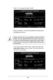
Please note that you want to create an extra RAID partition, please use the RAID utility under BIOS RAID environment. If you set up. Press to delete a RAID volume, please select the option Delete RAID Volume, press , and then follow the instructions on the screen. 16 If you install OS. After the completion, you will see the detailed information about the RAID that you are only allowed to create one RAID partition at a time under Windows environment to conigure RAID functions after you want to complete the setup of RAID.
Please note that you want to create an extra RAID partition, please use the RAID utility under BIOS RAID environment. If you set up. Press to delete a RAID volume, please select the option Delete RAID Volume, press , and then follow the instructions on the screen. 16 If you install OS. After the completion, you will see the detailed information about the RAID that you are only allowed to create one RAID partition at a time under Windows environment to conigure RAID functions after you want to complete the setup of RAID.
RAID Installation Guide
Page 17
3. Installing Windows® on a HDD under 2TB in RAID mode After the UEFI and RAID BIOS setup you may start installing Windows® 8.1 / 8.1 64-bit / 8 / 8 64-bit / 7 / 7 64-bit OS as usual. 17
3. Installing Windows® on a HDD under 2TB in RAID mode After the UEFI and RAID BIOS setup you may start installing Windows® 8.1 / 8.1 64-bit / 8 / 8 64-bit / 7 / 7 64-bit OS as usual. 17
RAID Installation Guide
Page 18
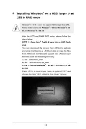
STEP 1: Copy Intel® RAID drivers into a USB lash disk You can download the drivers from ASRock's website and unzip the iles into a USB lash disk or copy the iles from ASRock's motherboard support CD. (Please copy the iles under the following directory: 32 bit: ..\i386\Win7_Intel.. 64-bit: .....\AMD64\Win7-64_Intel.. Please make sure to boot. 18 4. After the UEFI and RAID BIOS setup, please follow the steps below. Installing ...
STEP 1: Copy Intel® RAID drivers into a USB lash disk You can download the drivers from ASRock's website and unzip the iles into a USB lash disk or copy the iles from ASRock's motherboard support CD. (Please copy the iles under the following directory: 32 bit: ..\i386\Win7_Intel.. 64-bit: .....\AMD64\Win7-64_Intel.. Please make sure to boot. 18 4. After the UEFI and RAID BIOS setup, please follow the steps below. Installing ...

User Manual
Page 5
... Guide 43 2.13 Dual LAN and Teaming Operation Guide 44 Chapter 3 Software and Utilities Operation 45 3.1 Installing Drivers 45 3.2 A-Tuning 46 3.3 ASRock APP Shop 52 3.3.1 UI Overview 52 3.3.2 Apps 53 3.3.3 BIOS & Drivers 56 3.3.4 Setting 57 3.4 Start8 58 Chapter 4 UEFI SETUP UTILITY 61 4.1 Introduction 61 4.1.1 UEFI Menu Bar 61 4.1.2 Navigation Keys 62 4.2 Main...
... Guide 43 2.13 Dual LAN and Teaming Operation Guide 44 Chapter 3 Software and Utilities Operation 45 3.1 Installing Drivers 45 3.2 A-Tuning 46 3.3 ASRock APP Shop 52 3.3.1 UI Overview 52 3.3.2 Apps 53 3.3.3 BIOS & Drivers 56 3.3.4 Setting 57 3.4 Start8 58 Chapter 4 UEFI SETUP UTILITY 61 4.1 Introduction 61 4.1.1 UEFI Menu Bar 61 4.1.2 Navigation Keys 62 4.2 Main...

User Manual
Page 7
... BIOS setup. Chapter 3 contains the operation guide of this motherboard, please visit our website for speciic information about the model you are using. ASRock website http://www.asrock.com. 1.1 Package Contents • ASRock X99 WS Motherboard (EATX Form Factor) • ASRock X99 WS Quick Installation Guide • ASRock X99 WS Support CD • 1 x I/O Panel Shield • 2 x ASRock SLI_Bridge Cards • 1 x ASRock SLI_Bridge_3S Card • 1 x ASRock...
... BIOS setup. Chapter 3 contains the operation guide of this motherboard, please visit our website for speciic information about the model you are using. ASRock website http://www.asrock.com. 1.1 Package Contents • ASRock X99 WS Motherboard (EATX Form Factor) • ASRock X99 WS Quick Installation Guide • ASRock X99 WS Support CD • 1 x I/O Panel Shield • 2 x ASRock SLI_Bridge Cards • 1 x ASRock SLI_Bridge_3S Card • 1 x ASRock...

User Manual
Page 10
... Spike Protection)) • 1 x USB 3.0 Header (Supports 2 USB 3.0 ports) (Supports ESD Protection (ASRock Full Spike Protection)) • 1 x Dr. Debug with LED • 1 x Power Switch with LED • 1 x Reset Switch with Ultra M.2 Socket) * RAID is shared with LED • 1 x BIOS Selection Switch English 4 • 1 x Clear CMOS Switch • HD Audio Jacks: Rear Speaker / Central...
... Spike Protection)) • 1 x USB 3.0 Header (Supports 2 USB 3.0 ports) (Supports ESD Protection (ASRock Full Spike Protection)) • 1 x Dr. Debug with LED • 1 x Power Switch with LED • 1 x Reset Switch with Ultra M.2 Socket) * RAID is shared with LED • 1 x BIOS Selection Switch English 4 • 1 x Clear CMOS Switch • HD Audio Jacks: Rear Speaker / Central...

User Manual
Page 11
... to utilize the memory that there is required) * For detailed product information, please visit our website: http://www.asrock.com Please realize that Windows® cannot use. 5 We are not responsible for system usage under Windows® 32...Chassis/Power Fan Tachometer • CPU/Chassis Quiet Fan (Auto adjust chassis fan speed by overclocking. X99 WS BIOS Feature Hardware Monitor OS Certiications • 2 x 128Mb AMI UEFI Legal BIOS with overclocking, including adjusting the setting in the BIOS, applying Untied Overclocking Technology, or using third-party overclocking tools.
... to utilize the memory that there is required) * For detailed product information, please visit our website: http://www.asrock.com Please realize that Windows® cannot use. 5 We are not responsible for system usage under Windows® 32...Chassis/Power Fan Tachometer • CPU/Chassis Quiet Fan (Auto adjust chassis fan speed by overclocking. X99 WS BIOS Feature Hardware Monitor OS Certiications • 2 x 128Mb AMI UEFI Legal BIOS with overclocking, including adjusting the setting in the BIOS, applying Untied Overclocking Technology, or using third-party overclocking tools.

User Manual
Page 12
... CT1 M2_1 CMOS Battery SATA_PWR_1 1 S_SATA3_2_3 S_SATA3_0_1 PCIE2 Purity SoundTM 2 HD_AUDIO1 1 PCIE_PWR2 1 TBT1 COM1 1 PCIE3 X99 WS PCIE4 PCIE5 RoHS PCIE6 COM2 1 USB5_6 1 USB7_8 1 SATA3_4_5 Intel X99 SATA3_2_3 SATA3_0_1 Super I/O TPMS1 1 CHA_FAN1 CHA_FAN2 CLRMOS1 1 Reset BIOS_A_LED BIOS_B_LED 128Mb BIOS BIOS_A SPEAKER1 1 PLED1 1 A B BIOS_SEL1 128Mb BIOS BIOS_B Power PANEL1 PLED PWRBTN 1 HDLED RESET Dr. Debug English 6
... CT1 M2_1 CMOS Battery SATA_PWR_1 1 S_SATA3_2_3 S_SATA3_0_1 PCIE2 Purity SoundTM 2 HD_AUDIO1 1 PCIE_PWR2 1 TBT1 COM1 1 PCIE3 X99 WS PCIE4 PCIE5 RoHS PCIE6 COM2 1 USB5_6 1 USB7_8 1 SATA3_4_5 Intel X99 SATA3_2_3 SATA3_0_1 Super I/O TPMS1 1 CHA_FAN1 CHA_FAN2 CLRMOS1 1 Reset BIOS_A_LED BIOS_B_LED 128Mb BIOS BIOS_A SPEAKER1 1 PLED1 1 A B BIOS_SEL1 128Mb BIOS BIOS_B Power PANEL1 PLED PWRBTN 1 HDLED RESET Dr. Debug English 6

User Manual
Page 13
... HDD Saver Connector (SATA_PWR_1) 12 SATA3 Connectors (S_SATA3_0_1) 13 SATA3 Connectors (S_SATA3_2_3) 14 SATA3 Connectors (SATA3_4_5) 15 SATA3 Connectors (SATA3_2_3) 16 SATA3 Connectors (SATA3_0_1) 17 BIOS Selection Switch (BIOS_SEL1) 18 System Panel Header (PANEL1) 19 Power LED Header (PLED1) 20 Power Switch (PWRBTN1) 21 Reset Switch (RSTBTN1) 22 Chassis Speaker Header... COM Port Header (COM2) 30 COM Port Header (COM1) 31 PCIe Power Connector (PCIE_PWR2) 32 Front Panel Audio Header (HD_AUDIO1) 33 hunderbolt AIC Connector (TBT1) X99 WS 7 English No.
... HDD Saver Connector (SATA_PWR_1) 12 SATA3 Connectors (S_SATA3_0_1) 13 SATA3 Connectors (S_SATA3_2_3) 14 SATA3 Connectors (SATA3_4_5) 15 SATA3 Connectors (SATA3_2_3) 16 SATA3 Connectors (SATA3_0_1) 17 BIOS Selection Switch (BIOS_SEL1) 18 System Panel Header (PANEL1) 19 Power LED Header (PLED1) 20 Power Switch (PWRBTN1) 21 Reset Switch (RSTBTN1) 22 Chassis Speaker Header... COM Port Header (COM2) 30 COM Port Header (COM1) 31 PCIe Power Connector (PCIE_PWR2) 32 Front Panel Audio Header (HD_AUDIO1) 33 hunderbolt AIC Connector (TBT1) X99 WS 7 English No.
User Manual
Page 26
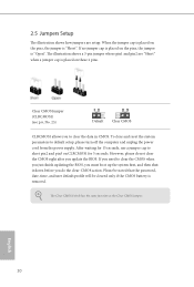
Clear CMOS Jumper (CLRCMOS1) (see p.6, No. 25) Default Clear CMOS CLRCMOS1 allows you update the BIOS. However, please do the clear-CMOS action. English 20 If no jumper cap is placed on CLRCMOS1 for 15 seconds, use a jumper cap to clear ... a 3-pin jumper whose pin1 and pin2 are setup. To clear and reset the system parameters to clear the CMOS when you just inish updating the BIOS, you must boot up the system irst, and then shut it down before you do not clear the CMOS right ater you to short pin2...
Clear CMOS Jumper (CLRCMOS1) (see p.6, No. 25) Default Clear CMOS CLRCMOS1 allows you update the BIOS. However, please do the clear-CMOS action. English 20 If no jumper cap is placed on CLRCMOS1 for 15 seconds, use a jumper cap to clear ... a 3-pin jumper whose pin1 and pin2 are setup. To clear and reset the system parameters to clear the CMOS when you just inish updating the BIOS, you must boot up the system irst, and then shut it down before you do not clear the CMOS right ater you to short pin2...

User Manual
Page 32
... CMOS Switch allows users to quickly clear the CMOS values. Normally, the system will take over on the primary BIOS. English 26 Users may refer to the BIOS LEDs (BIOS_A_LED or BIOS_ B_LED) to identify which enhances the safety and stability of your computer and unplug the power... supply. Clear CMOS Switch (CLRCBTN) (see p.6, No. 21) Reset Reset Switch allows users to quickly reset the system. BIOS Selection Switch (BIOS_SEL1) (see p.6, No. 20) Power Power Switch allows users to quickly turn on /of the system. his function is workable ...
... CMOS Switch allows users to quickly clear the CMOS values. Normally, the system will take over on the primary BIOS. English 26 Users may refer to the BIOS LEDs (BIOS_A_LED or BIOS_ B_LED) to identify which enhances the safety and stability of your computer and unplug the power... supply. Clear CMOS Switch (CLRCBTN) (see p.6, No. 21) Reset Reset Switch allows users to quickly reset the system. BIOS Selection Switch (BIOS_SEL1) (see p.6, No. 20) Power Power Switch allows users to quickly turn on /of the system. his function is workable ...

User Manual
Page 56
Please leave your contact information along with your computer. Tech Service Contact Tech Service if you have problems with details of BIOS or drivers. Live Update Check for newer versions of the problem. 50 English
Please leave your contact information along with your computer. Tech Service Contact Tech Service if you have problems with details of BIOS or drivers. Live Update Check for newer versions of the problem. 50 English
User Manual
Page 62
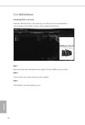
3.3.3 BIOS & Drivers Installing BIOS or Drivers When the "BIOS & Drivers" tab is selected, you want to update. Click to select one or more details. Click on Step 2 to start the update process. 56 English Step 1 Please check the item information before update. Please update them all soon. Step 3 Click Update to see more items you will see a list of recommended or critical updates for the BIOS or drivers.
3.3.3 BIOS & Drivers Installing BIOS or Drivers When the "BIOS & Drivers" tab is selected, you want to update. Click to select one or more details. Click on Step 2 to start the update process. 56 English Step 1 Please check the item information before update. Please update them all soon. Step 3 Click Update to see more items you will see a list of recommended or critical updates for the BIOS or drivers.

User Manual
Page 86
... the USB ports. Legacy USB Support Enable or disable Legacy OS Support for USB 3.0 devices. If you encounter USB compatibility issues it is disabled in BIOS). Set [Auto] to support USB devices under the UEFI setup and Windows/Linux operating systems only. Legacy USB 3.0 Support Enable or disable Legacy OS Support... the USB 3.0 driver ater entering the OS (USB 3.0 is recommended to disable the USB 3.0 ports. If you encounter USB compatibility issues it is enabled in BIOS).
... the USB ports. Legacy USB Support Enable or disable Legacy OS Support for USB 3.0 devices. If you encounter USB compatibility issues it is disabled in BIOS). Set [Auto] to support USB devices under the UEFI setup and Windows/Linux operating systems only. Legacy USB 3.0 Support Enable or disable Legacy OS Support... the USB 3.0 driver ater entering the OS (USB 3.0 is recommended to disable the USB 3.0 ports. If you encounter USB compatibility issues it is enabled in BIOS).

User Manual
Page 90
... disk drive to install the drivers from the support CD to plug in RAID mode. Please setup network coniguration before using Internet Flash. *For BIOS backup and recovery purpose, it is recommended to your PC. Ater copying the drivers please change the SATA mode to the secondary lash ROM....ROM images are having trouble with your USB storage device. You can start installing the operating system in your OS. UEFI Tech Service Contact ASRock Tech Service if you to copy the RAID driver from our support CD, Easy Driver Installer is recommended to proceed the re-detection for ...
... disk drive to install the drivers from the support CD to plug in RAID mode. Please setup network coniguration before using Internet Flash. *For BIOS backup and recovery purpose, it is recommended to your PC. Ater copying the drivers please change the SATA mode to the secondary lash ROM....ROM images are having trouble with your USB storage device. You can start installing the operating system in your OS. UEFI Tech Service Contact ASRock Tech Service if you to copy the RAID driver from our support CD, Easy Driver Installer is recommended to proceed the re-detection for ...

Quick Installation Guide
Page 3
Motherboard Layout X99 WS USB 2.0 T: USB1 B: USB2 PS2 Keyboard /Mouse CLRC BTN1 USB 2.0 T: USB3 B: USB4 ATX12V1 2011-3 Socket CPU_FAN1 CPU_FAN2 ATXPWR1 DDR4_D2 (64 bit, 284-... 1 S_SATA3_2_3 S_SATA3_0_1 PCIE2 Purity SoundTM 2 HD_AUDIO1 1 PCIE_PWR2 1 TBT1 COM1 1 PCIE3 X99 WS PCIE4 PCIE5 RoHS PCIE6 COM2 1 USB5_6 1 USB7_8 1 SATA3_4_5 Intel X99 SATA3_2_3 SATA3_0_1 Super I/O TPMS1 1 CHA_FAN1 CHA_FAN2 CLRMOS1 1 Reset BIOS_A_LED BIOS_B_LED 128Mb BIOS BIOS_A SPEAKER1 1 PLED1 1 A B BIOS_SEL1 128Mb BIOS BIOS_B Power PANEL1 PLED PWRBTN 1 HDLED RESET Dr. Debug English 1
Motherboard Layout X99 WS USB 2.0 T: USB1 B: USB2 PS2 Keyboard /Mouse CLRC BTN1 USB 2.0 T: USB3 B: USB4 ATX12V1 2011-3 Socket CPU_FAN1 CPU_FAN2 ATXPWR1 DDR4_D2 (64 bit, 284-... 1 S_SATA3_2_3 S_SATA3_0_1 PCIE2 Purity SoundTM 2 HD_AUDIO1 1 PCIE_PWR2 1 TBT1 COM1 1 PCIE3 X99 WS PCIE4 PCIE5 RoHS PCIE6 COM2 1 USB5_6 1 USB7_8 1 SATA3_4_5 Intel X99 SATA3_2_3 SATA3_0_1 Super I/O TPMS1 1 CHA_FAN1 CHA_FAN2 CLRMOS1 1 Reset BIOS_A_LED BIOS_B_LED 128Mb BIOS BIOS_A SPEAKER1 1 PLED1 1 A B BIOS_SEL1 128Mb BIOS BIOS_B Power PANEL1 PLED PWRBTN 1 HDLED RESET Dr. Debug English 1


