RAID Installation Guide
Page 1
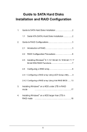
...RAID mode 17 4. Guide to SATA Hard Disks Installation and RAID Coniguration 1. Installing Windows® on a HDD under 2TB in RAID mode 18 1 Guide to SATA Hard Disks Installation 2 1.1 Serial ATA (SATA) Hard Disks Installation 2 2. Guide to RAID Conigurations 3 2.1 Introduction of RAID 3 2.2 RAID Coniguration Precautions 6 2.3 Installing Windows® 8.1 / 8.1 64-bit / 8 / 8 64-bit / 7 / 7 64-bit With RAID Functions 7 2.4 Coniguring a RAID array 8 2.4.1 Coniguring a RAID array Using UEFI Setup Utility ...... 9 2.4.2 Coniguring a RAID array Using Intel RAID BIOS...
...RAID mode 17 4. Guide to SATA Hard Disks Installation and RAID Coniguration 1. Installing Windows® on a HDD under 2TB in RAID mode 18 1 Guide to SATA Hard Disks Installation 2 1.1 Serial ATA (SATA) Hard Disks Installation 2 2. Guide to RAID Conigurations 3 2.1 Introduction of RAID 3 2.2 RAID Coniguration Precautions 6 2.3 Installing Windows® 8.1 / 8.1 64-bit / 8 / 8 64-bit / 7 / 7 64-bit With RAID Functions 7 2.4 Coniguring a RAID array 8 2.4.1 Coniguring a RAID array Using UEFI Setup Utility ...... 9 2.4.2 Coniguring a RAID array Using Intel RAID BIOS...
RAID Installation Guide
Page 3
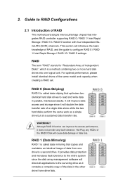
... HDDs of the same model and capacity when creating a RAID set. RAID The term "RAID" stands for "Redundant Array of RAID This motherboard adopts Intel southbridge chipset that integrates RAID controller supporting RAID 0 / RAID 1/ Intel Rapid Storage / RAID 10 / RAID 5 function with four independent Serial ATA (SATA) channels. RAID 0 (Data Striping) RAID 0 is called data striping that copies and maintains an identical image of data from one drive to RAID Conigurations 2.1 Introduction of Independent Disks...
... HDDs of the same model and capacity when creating a RAID set. RAID The term "RAID" stands for "Redundant Array of RAID This motherboard adopts Intel southbridge chipset that integrates RAID controller supporting RAID 0 / RAID 1/ Intel Rapid Storage / RAID 10 / RAID 5 function with four independent Serial ATA (SATA) channels. RAID 0 (Data Striping) RAID 0 is called data striping that copies and maintains an identical image of data from one drive to RAID Conigurations 2.1 Introduction of Independent Disks...
RAID Installation Guide
Page 7
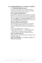
... 2: Use ASRock Easy RAID Installer Easy RAID Installer can copy the RAID driver from a support CD to your USB lash drive into a USB port. Plug in your USB storage device with RAID functions, please follow the procedures below. STEP 3: Set RAID coniguration Please refer to p.8 -17 of this feature is not available for instructions on your RAID coniguration. Boot your SATA / SATA2 / SATA3 HDDs with just one simple click in the BIOS before you want to install Windows...
... 2: Use ASRock Easy RAID Installer Easy RAID Installer can copy the RAID driver from a support CD to your USB lash drive into a USB port. Plug in your USB storage device with RAID functions, please follow the procedures below. STEP 3: Set RAID coniguration Please refer to p.8 -17 of this feature is not available for instructions on your RAID coniguration. Boot your SATA / SATA2 / SATA3 HDDs with just one simple click in the BIOS before you want to install Windows...
RAID Installation Guide
Page 8
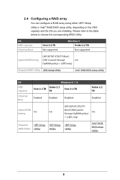
...RAID array using either UEFI Setup Utility or Intel® RAID BIOS setup utility, depending on the HDD capacity and the OS you are installing. OS HDD Capacity Ultra Fast Boot Over 2.2 TB Not supported Windows 7 Under 2.2 TB Not supported Option ROM Setting UEFI SETUP UTILITY\Boot\ CSM [Launch Storage n/a OpROM policy] = [UEFI only] Required RAID Utility UEFI Setup Utility Intel® RAID BIOS setup utility OS HDD Capacity Ultra Fast Boot Windows 8.1 / 8 Under 2.2 Over 2.2 TB Over 2.2 TB TB Enabled Enabled Disabled Under 2.2 TB Disabled UEFI SETUP UTILITY\ Option ROM...
...RAID array using either UEFI Setup Utility or Intel® RAID BIOS setup utility, depending on the HDD capacity and the OS you are installing. OS HDD Capacity Ultra Fast Boot Over 2.2 TB Not supported Windows 7 Under 2.2 TB Not supported Option ROM Setting UEFI SETUP UTILITY\Boot\ CSM [Launch Storage n/a OpROM policy] = [UEFI only] Required RAID Utility UEFI Setup Utility Intel® RAID BIOS setup utility OS HDD Capacity Ultra Fast Boot Windows 8.1 / 8 Under 2.2 Over 2.2 TB Over 2.2 TB TB Enabled Enabled Disabled Under 2.2 TB Disabled UEFI SETUP UTILITY\ Option ROM...
RAID Installation Guide
Page 18
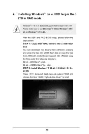
... launch boot menu at system POST and choose the item "UEFI:" to use Windows® 7 64-bit, Windows® 8 64bit, or Windows® 8.1 64-bit. Please make sure to boot. 18 After the UEFI and RAID BIOS setup, please follow the steps below. Installing Windows® on a HDD larger than 2TB in RAID mode Windows® 7 / 8 / 8.1 does not support HDD's larger than 2TB. STEP 1: Copy Intel® RAID drivers into a USB lash disk You can download the drivers from ASRock...
... launch boot menu at system POST and choose the item "UEFI:" to use Windows® 7 64-bit, Windows® 8 64bit, or Windows® 8.1 64-bit. Please make sure to boot. 18 After the UEFI and RAID BIOS setup, please follow the steps below. Installing Windows® on a HDD larger than 2TB in RAID mode Windows® 7 / 8 / 8.1 does not support HDD's larger than 2TB. STEP 1: Copy Intel® RAID drivers into a USB lash disk You can download the drivers from ASRock...
RAID Installation Guide
Page 19
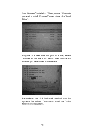
page, please click "Load Driver". Please keep the USB flash disk installed until the system's first reboot. select "Browse" to install the OS by following the instructions. 19 Plug the USB flash disk into your USB port; Continue to find the RAID driver. Start Windows® Installation. Then choose the directory you want to install Windows?" When you see "Where do you have copied in the irst step.
page, please click "Load Driver". Please keep the USB flash disk installed until the system's first reboot. select "Browse" to install the OS by following the instructions. 19 Plug the USB flash disk into your USB port; Continue to find the RAID driver. Start Windows® Installation. Then choose the directory you want to install Windows?" When you see "Where do you have copied in the irst step.
RAID Installation Guide
Page 20
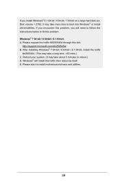
... ix this problem. Windows® will need to follow the instructions below to boot into Windows® or install driver/utilities. Please request the hotix KB2505454 through this problem, you install Windows® 8.1 64-bit / 8 64-bit / 7 64-bit on a large hard disk (ex. Please start to reboot.) D. Windows® 7 64-bit / 8 64-bit / 8.1 64-bit: A. E. Disk volume > 2TB), it may take about 5 minutes to install motherboard drivers and utilities. 20 If you will install this hotix...
... ix this problem. Windows® will need to follow the instructions below to boot into Windows® or install driver/utilities. Please request the hotix KB2505454 through this problem, you install Windows® 8.1 64-bit / 8 64-bit / 7 64-bit on a large hard disk (ex. Please start to reboot.) D. Windows® 7 64-bit / 8 64-bit / 8.1 64-bit: A. E. Disk volume > 2TB), it may take about 5 minutes to install motherboard drivers and utilities. 20 If you will install this hotix...
Intel Rapid Storage Guide
Page 1
... protection against a hard drive failure when t he power consum pt ion of enhanced perform ance and lower power consum ption. When the failed drive is rem oved and a replacem ent hard drive is installed, data fault tolerance is im proved t hrough Nat ive Com m and Queuing ( NCQ) . When using one drive, the user can also im prove t he chipset and Serial ATA ( SATA) hard drive. 1 t olerant RAI...
... protection against a hard drive failure when t he power consum pt ion of enhanced perform ance and lower power consum ption. When the failed drive is rem oved and a replacem ent hard drive is installed, data fault tolerance is im proved t hrough Nat ive Com m and Queuing ( NCQ) . When using one drive, the user can also im prove t he chipset and Serial ATA ( SATA) hard drive. 1 t olerant RAI...
Intel Rapid Storage Guide
Page 16
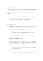
... St orage Technology driver using F6 w hen in RAI D m ode or AHCI m ode, t he F6 inst allat ion m et hod. 1. Set up will N ot e t em porarily cont inue loading drivers. You can use a USB floppy drive or create a slipstream version of Windows setup ( during OS installation using t he F6 inst allat ion m et hod m ust be prom pt ed wit h a screen asking you to load the driver during text...
... St orage Technology driver using F6 w hen in RAI D m ode or AHCI m ode, t he F6 inst allat ion m et hod. 1. Set up will N ot e t em porarily cont inue loading drivers. You can use a USB floppy drive or create a slipstream version of Windows setup ( during OS installation using t he F6 inst allat ion m et hod m ust be prom pt ed wit h a screen asking you to load the driver during text...

Quick Installation Guide
Page 4
...) 15 SATA3 Connectors (SATA3_0_3) 16 SATA3 Connectors (SATA3_1_4) 17 SATA3 Connectors (SATA3_2_5) 18 Power LED Header (PLED1) 19 Chassis Speaker Header (SPEAKER1) 20 System Panel Header (PANEL1) 21 Power Switch (PWRBTN1) 22 HDD Saver Connector (SATA_PWR_1) 23 Reset Switch (RSTBTN1) 24 Chassis Fan Connector (CHA_FAN2) 25 Chassis Fan Connector (CHA_FAN1) 26 USB 2.0 Header (USB3_4) 27 USB 2.0 Header (USB5_6) 28 BIOS Selection Switch (BIOS_SEL1) 29 Clear CMOS Jumper (CLRCMOS1) 30 COM Port Header (COM1) 31 hunderbolt AIC Connector (TBT1) 32 TPM Header (TPMS1) 33 Front Panel Audio Header (HD_AUDIO1...
...) 15 SATA3 Connectors (SATA3_0_3) 16 SATA3 Connectors (SATA3_1_4) 17 SATA3 Connectors (SATA3_2_5) 18 Power LED Header (PLED1) 19 Chassis Speaker Header (SPEAKER1) 20 System Panel Header (PANEL1) 21 Power Switch (PWRBTN1) 22 HDD Saver Connector (SATA_PWR_1) 23 Reset Switch (RSTBTN1) 24 Chassis Fan Connector (CHA_FAN2) 25 Chassis Fan Connector (CHA_FAN1) 26 USB 2.0 Header (USB3_4) 27 USB 2.0 Header (USB5_6) 28 BIOS Selection Switch (BIOS_SEL1) 29 Clear CMOS Jumper (CLRCMOS1) 30 COM Port Header (COM1) 31 hunderbolt AIC Connector (TBT1) 32 TPM Header (TPMS1) 33 Front Panel Audio Header (HD_AUDIO1...
Quick Installation Guide
Page 8
... Installation Guide • ASRock X99 Extreme6 Support CD • 1 x I/O Panel Shield • 1 x ASRock SLI_Bridge_2S Card • 1 x ASRock 3-Way SLI-2S1S Bridge Card • 4 x Serial ATA (SATA) Data Cables (Optional) • 1 x HDD Saver Cable • 1 x Screw for Ultra M.2 Socket • 1 x Screw for mini-PCIe Slot 6 English Because the motherboard speciications and the BIOS sotware might be updated, the content of this documentation will be subject to quality and endurance. You may ind the latest VGA cards and CPU support list...
... Installation Guide • ASRock X99 Extreme6 Support CD • 1 x I/O Panel Shield • 1 x ASRock SLI_Bridge_2S Card • 1 x ASRock 3-Way SLI-2S1S Bridge Card • 4 x Serial ATA (SATA) Data Cables (Optional) • 1 x HDD Saver Cable • 1 x Screw for Ultra M.2 Socket • 1 x Screw for mini-PCIe Slot 6 English Because the motherboard speciications and the BIOS sotware might be updated, the content of this documentation will be subject to quality and endurance. You may ind the latest VGA cards and CPU support list...
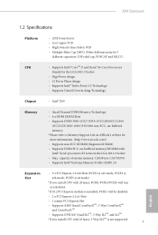
Quick Installation Guide
Page 9
.../x8/x4. * If M.2 PCI Express module is installed, PCIE5 will be disabled. • 2 x PCI Express 2.0 x1 Slots • 1 x mini-PCI Express Slot • Supports AMD Quad CrossFireXTM, 3-Way CrossFireXTM and CrossFireXTM • Supports NVIDIA® Quad SLITM, 3-Way SLITM and SLITM * If you install CPU with Intel® Xeon® processors E5 series in the LGA 2011-3 Socket • Max. PCIE3 @ Slot x16 mode; X99 Extreme6 1.2 Speciications Platform • ATX Form Factor • 2oz...
.../x8/x4. * If M.2 PCI Express module is installed, PCIE5 will be disabled. • 2 x PCI Express 2.0 x1 Slots • 1 x mini-PCI Express Slot • Supports AMD Quad CrossFireXTM, 3-Way CrossFireXTM and CrossFireXTM • Supports NVIDIA® Quad SLITM, 3-Way SLITM and SLITM * If you install CPU with Intel® Xeon® processors E5 series in the LGA 2011-3 Socket • Max. PCIE3 @ Slot x16 mode; X99 Extreme6 1.2 Speciications Platform • ATX Form Factor • 2oz...
Quick Installation Guide
Page 11
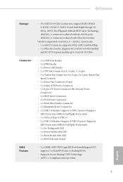
... PCI Express module up to Gen3 x4 (32 Gb/s) Connector • 1 x COM Port Header • 1 x TPM Header • 1 x Power LED Header • 2 x CPU Fan Connectors (1 x 4-pin, 1 x 3-pin) • 3 x Chassis Fan Connectors (1 x 4-pin, 2 x 3-pin) (Smart Fan Speed Control) • 1 x Power Fan Connector (3-pin) • 1 x 24 pin ATX Power Connector • 1 x 8 pin 12V Power Connector (Hi-Density Power Connector) • 1 x HDD Saver Connector • 1 x PCIe Power Connector • 1 x Front Panel Audio Connector • 1 x hunderbolt AIC Connector • 2 x USB 2.0 Headers (support...
... PCI Express module up to Gen3 x4 (32 Gb/s) Connector • 1 x COM Port Header • 1 x TPM Header • 1 x Power LED Header • 2 x CPU Fan Connectors (1 x 4-pin, 1 x 3-pin) • 3 x Chassis Fan Connectors (1 x 4-pin, 2 x 3-pin) (Smart Fan Speed Control) • 1 x Power Fan Connector (3-pin) • 1 x 24 pin ATX Power Connector • 1 x 8 pin 12V Power Connector (Hi-Density Power Connector) • 1 x HDD Saver Connector • 1 x PCIe Power Connector • 1 x Front Panel Audio Connector • 1 x hunderbolt AIC Connector • 2 x USB 2.0 Headers (support...

Quick Installation Guide
Page 12
... possible damage caused by CPU temperature) • CPU/Chassis Fan multi-speed control • Voltage monitoring: +12V, +5V, +3.3V, CPU Input Voltage, CPU Internal Voltages • Microsot® Windows® 8.1 32-bit / 8.1 64-bit / 8 32-bit / 8 64bit / 7 32-bit / 7 64-bit • FCC, CE, WHQL • ErP/EuP Ready (ErP/EuP ready power supply is a certain risk involved with overclocking, including adjusting the setting in the BIOS, applying Untied Overclocking Technology, or using third-party overclocking tools. We are...
... possible damage caused by CPU temperature) • CPU/Chassis Fan multi-speed control • Voltage monitoring: +12V, +5V, +3.3V, CPU Input Voltage, CPU Internal Voltages • Microsot® Windows® 8.1 32-bit / 8.1 64-bit / 8 32-bit / 8 64bit / 7 32-bit / 7 64-bit • FCC, CE, WHQL • ErP/EuP Ready (ErP/EuP ready power supply is a certain risk involved with overclocking, including adjusting the setting in the BIOS, applying Untied Overclocking Technology, or using third-party overclocking tools. We are...

Quick Installation Guide
Page 20
... SLITM Mode x16 N/A x16 N/A N/A hree Graphics Cards in 3-Way CrossFireXTM Mode x16 N/A x16 N/A x8 or 3-Way SLITM Mode English 18 2.4 Expansion Slots (PCI Express Slots) here are 5 PCI Express slots and 1 mini-PCI Express slot on the motherboard. PCIE2 (PCIe 2.0 x1 slot) is unplugged. Before installing an expansion card, please make sure that the power supply is switched of the expansion card and make necessary hardware settings for WiFi module. mini-PCIe slot: MINI_PCIE1 (mini-PCIe slot) is used for PCI Express...
... SLITM Mode x16 N/A x16 N/A N/A hree Graphics Cards in 3-Way CrossFireXTM Mode x16 N/A x16 N/A x8 or 3-Way SLITM Mode English 18 2.4 Expansion Slots (PCI Express Slots) here are 5 PCI Express slots and 1 mini-PCI Express slot on the motherboard. PCIE2 (PCIe 2.0 x1 slot) is unplugged. Before installing an expansion card, please make sure that the power supply is switched of the expansion card and make necessary hardware settings for WiFi module. mini-PCIe slot: MINI_PCIE1 (mini-PCIe slot) is used for PCI Express...

Quick Installation Guide
Page 23
... connectors. When connecting your system using the power switch. he LED is of your chassis front panel module to this header to this header, make sure the wire assignments and the pin assignments are NOT jumpers. English Power LED Header (3-pin PLED1) (see p.1, No. 20) PLED+ PLEDPWRBTN# GND 1 GND RESET# GND HDLEDHDLED+ Connect the power switch, reset switch and system status indicator on when the system is in S1/S3 sleep state. X99 Extreme6 2.6 Onboard Headers and Connectors Onboard headers and connectors...
... connectors. When connecting your system using the power switch. he LED is of your chassis front panel module to this header to this header, make sure the wire assignments and the pin assignments are NOT jumpers. English Power LED Header (3-pin PLED1) (see p.1, No. 20) PLED+ PLEDPWRBTN# GND 1 GND RESET# GND HDLEDHDLED+ Connect the power switch, reset switch and system status indicator on when the system is in S1/S3 sleep state. X99 Extreme6 2.6 Onboard Headers and Connectors Onboard headers and connectors...

Quick Installation Guide
Page 26
... 3) PCIe Power Connector (4-pin PCIE_PWR1) (see p.1, No. 34) HDD Saver Connector (4-pin SATA_PWR_1) (see p.1, No. 22) hunderbolt AIC Connector (5-pin TBT1) (see p.1, No. 6) 4 3 21 GND +12V CPU_FAN_SPEED FAN_SPEED_CONTROL GND FAN_VOLTAGE CPU_FAN_SPEED his motherboard provides a 4-Pin CPU fan (Quiet Fan) connector. English 24 his motherboard provides a 24-pin ATX power connector. Please connect a 4 pin molex power cable to this connector to this connector when more than three graphics cards are installed. Please connect a hunderbolt™ add-in card (AIC) to Pin 1-3. To use...
... 3) PCIe Power Connector (4-pin PCIE_PWR1) (see p.1, No. 34) HDD Saver Connector (4-pin SATA_PWR_1) (see p.1, No. 22) hunderbolt AIC Connector (5-pin TBT1) (see p.1, No. 6) 4 3 21 GND +12V CPU_FAN_SPEED FAN_SPEED_CONTROL GND FAN_VOLTAGE CPU_FAN_SPEED his motherboard provides a 4-Pin CPU fan (Quiet Fan) connector. English 24 his motherboard provides a 24-pin ATX power connector. Please connect a 4 pin molex power cable to this connector to this connector when more than three graphics cards are installed. Please connect a hunderbolt™ add-in card (AIC) to Pin 1-3. To use...

Quick Installation Guide
Page 28
... boot. English 26 Ater that, use "Secure Backup UEFI" in the UEFI Setup Utility to duplicate a working copy of the BIOS iles to the primary BIOS to update the backup BIOS manually. Power Switch (PWRBTN) (see p.4, No. 14) Clear CMOS Switch allows users to quickly clear the CMOS values. Reset Switch (RSTBTN) (see p.1, No. 19) AB BIOS Selection Switch allows the system to boot from diferent BIOS. his motherboard has two BIOS chips, a primary BIOS (BIOS_A) and a backup BIOS (BIOS_ B), which BIOS...
... boot. English 26 Ater that, use "Secure Backup UEFI" in the UEFI Setup Utility to duplicate a working copy of the BIOS iles to the primary BIOS to update the backup BIOS manually. Power Switch (PWRBTN) (see p.4, No. 14) Clear CMOS Switch allows users to quickly clear the CMOS values. Reset Switch (RSTBTN) (see p.1, No. 19) AB BIOS Selection Switch allows the system to boot from diferent BIOS. his motherboard has two BIOS chips, a primary BIOS (BIOS_A) and a backup BIOS (BIOS_ B), which BIOS...
Quick Installation Guide
Page 29
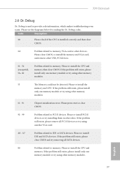
... slots. Please re-install the memory and CPU. Please re-install PCI-E devices or try using other memory modules. 61 - 91 Chipset initialization error. English 27 X99 Extreme6 2.8 Dr. Debug Dr. Debug is installed correctly and then clear CMOS. 0d Problem related to memory, VGA card or other devices. Please clear CMOS, re-install the memory and VGA card, and remove other USB, PCI devices. 01 - 54 (except 0d), 5A- 60 Problem related to IDE or SATA devices. If the problem still exists, please install only one memory...
... slots. Please re-install the memory and CPU. Please re-install PCI-E devices or try using other memory modules. 61 - 91 Chipset initialization error. English 27 X99 Extreme6 2.8 Dr. Debug Dr. Debug is installed correctly and then clear CMOS. 0d Problem related to memory, VGA card or other devices. Please clear CMOS, re-install the memory and VGA card, and remove other USB, PCI devices. 01 - 54 (except 0d), 5A- 60 Problem related to IDE or SATA devices. If the problem still exists, please install only one memory...

Quick Installation Guide
Page 34
... this motherboard allows you to a SATA port on the motherboard. 2.10 HDD Saver Cable Installation Guide The HDD Saver Connector on this user manual. 32 English Connect one end of the HDD Saver Cable to install the HDD Saver Cable. hen connect the other end to two SATA HDDs. 2. Please follow the steps below to the HDD Saver Connector (SATA_ PWR_1) placed near the SATA ports. Connection Diagram 1 HDD Saver Cable 2 SATA data cable *he HDD Saver Connector supports up to your SATA HDD(s). * he diagram shown...
... this motherboard allows you to a SATA port on the motherboard. 2.10 HDD Saver Cable Installation Guide The HDD Saver Connector on this user manual. 32 English Connect one end of the HDD Saver Cable to install the HDD Saver Cable. hen connect the other end to two SATA HDDs. 2. Please follow the steps below to the HDD Saver Connector (SATA_ PWR_1) placed near the SATA ports. Connection Diagram 1 HDD Saver Cable 2 SATA data cable *he HDD Saver Connector supports up to your SATA HDD(s). * he diagram shown...


