
Software/BIOS Setup Guide
Page 3
... 6 2.2 ASRock Live Update & APP Shop 7 2.2.1 Installing ASRock Live Update & APP Shop 7 2.2.2 UI Overview 8 2.2.3 Apps 9 2.2.4 BIOS & Drivers 12 2.2.5 Setting 13 2.3 ASRock Motherboard Utility (A-Tuning) 14 2.3.1 Installing ASRock Motherboard Utility (A-Tuning) 14 2.3.2 Using ASRock Motherboard Utility (A-Tuning) 14 2.4 ASRock Motherboard Utility (Phantom Gaming Tuning) 17 2.4.1 Installing ASRock Motherboard Utility (Phantom Gaming Tuning) 17 2.4.2 Using ASRock Motherboard Utility (Phantom Gaming Tuning)17 2.5 ASRock Polychrome SYNC 20 2.5.1 Connecting the LED Strip...
... 6 2.2 ASRock Live Update & APP Shop 7 2.2.1 Installing ASRock Live Update & APP Shop 7 2.2.2 UI Overview 8 2.2.3 Apps 9 2.2.4 BIOS & Drivers 12 2.2.5 Setting 13 2.3 ASRock Motherboard Utility (A-Tuning) 14 2.3.1 Installing ASRock Motherboard Utility (A-Tuning) 14 2.3.2 Using ASRock Motherboard Utility (A-Tuning) 14 2.4 ASRock Motherboard Utility (Phantom Gaming Tuning) 17 2.4.1 Installing ASRock Motherboard Utility (Phantom Gaming Tuning) 17 2.4.2 Using ASRock Motherboard Utility (Phantom Gaming Tuning)17 2.5 ASRock Polychrome SYNC 20 2.5.1 Connecting the LED Strip...

Software/BIOS Setup Guide
Page 5
... support related to this motherboard, please visit our website for specific information about the model you purchased. ASRock website http:// www.asrock.com. 1 Software Setup Guide • Auto Driver Installer (ADI) • ASRock Live Update & APP Shop • ASRock Motherboard Utility (A-Tuning) • ASRock Motherboard Utility (Phantom Gaming Tuning) • ASRock Polychrome SYNC • Nahimic Audio BIOS Setup Guide • UEFI Setup Utility Because the motherboard specifications and the software might be updated, the content of this documentation occur, the updated version...
... support related to this motherboard, please visit our website for specific information about the model you purchased. ASRock website http:// www.asrock.com. 1 Software Setup Guide • Auto Driver Installer (ADI) • ASRock Live Update & APP Shop • ASRock Motherboard Utility (A-Tuning) • ASRock Motherboard Utility (Phantom Gaming Tuning) • ASRock Polychrome SYNC • Nahimic Audio BIOS Setup Guide • UEFI Setup Utility Because the motherboard specifications and the software might be updated, the content of this documentation occur, the updated version...

Software/BIOS Setup Guide
Page 7
... using the Auto Driver Installer. If you boot into the system, and a notification will see the Auto Driver Installer icon on your computer to skip the installation. 1. Step 3 When it's completed, you want to install Auto Driver Installer. The item is set to change the setting in the BIOS is enabled by default; Now connect your desktop and then the Auto Driver Installer appears. 3 An available Internet connection is a prerequisite for users to install drivers only when the "Auto Driver Installer...
... using the Auto Driver Installer. If you boot into the system, and a notification will see the Auto Driver Installer icon on your computer to skip the installation. 1. Step 3 When it's completed, you want to install Auto Driver Installer. The item is set to change the setting in the BIOS is enabled by default; Now connect your desktop and then the Auto Driver Installer appears. 3 An available Internet connection is a prerequisite for users to install drivers only when the "Auto Driver Installer...

Software/BIOS Setup Guide
Page 9
... go to the "Tool" menu in the BIOS setting, and set the "Auto Driver Installer" item to complete the procedure. When driver installation is completed, the Auto Driver Installer tool will be uninstalled automatically from your system may reboot and continue installing remaining item(s)". Click "Ok" to [Enabled]. 5 After driver installation, the Auto Driver Installer will be removed. AMD X670/B650 Series Step 5 A messages pops up saying, "Installation has been successfully completed! Click...
... go to the "Tool" menu in the BIOS setting, and set the "Auto Driver Installer" item to complete the procedure. When driver installation is completed, the Auto Driver Installer tool will be uninstalled automatically from your system may reboot and continue installing remaining item(s)". Click "Ok" to [Enabled]. 5 After driver installation, the Auto Driver Installer will be removed. AMD X670/B650 Series Step 5 A messages pops up saying, "Installation has been successfully completed! Click...

Software/BIOS Setup Guide
Page 29
... the UEFI utility are for instructions. 3.1.1 Entering BIOS Setup You may cause system instability, mulfunction or boot failure. UEFI Settings and options may also restart by pressing the reset button on the system chassis. The UEFI system works with its test routines. This BIOS utility can perform the Power-On Self-Test (POST) during system startup, record hardware parameters of a trained service person. AMD X670/B650 Series Chapter 3 UEFI SETUP UTILITY 3.1 Introduction ASRock UEFI (Unified Extensible Firmware Interface) is turned...
... the UEFI utility are for instructions. 3.1.1 Entering BIOS Setup You may cause system instability, mulfunction or boot failure. UEFI Settings and options may also restart by pressing the reset button on the system chassis. The UEFI system works with its test routines. This BIOS utility can perform the Power-On Self-Test (POST) during system startup, record hardware parameters of a trained service person. AMD X670/B650 Series Chapter 3 UEFI SETUP UTILITY 3.1 Introduction ASRock UEFI (Unified Extensible Firmware Interface) is turned...

Software/BIOS Setup Guide
Page 37
...)] 33 AMD X670/B650 Series Twrrd The minimum number of cycles from the last clock of virtual CAS of the first writeburst operation to configure DRAM Bus Control options. Configuration options: [Auto] [RTT_OFF] [RZQ (240)] [RZQ/2 (120)] [RZQ/3 (80)] [RZQ/6 (60)] [RZQ/5 (48)] [RZQ/6 (40)] [RZQ/7 (34)] Dram ODT impedance RTT_PARK Allows you to specify the Dram ODT impedance RTT_PARK. DRAM Bus Control Configuration Press [Enter] to the clock in...
...)] 33 AMD X670/B650 Series Twrrd The minimum number of cycles from the last clock of virtual CAS of the first writeburst operation to configure DRAM Bus Control options. Configuration options: [Auto] [RTT_OFF] [RZQ (240)] [RZQ/2 (120)] [RZQ/3 (80)] [RZQ/6 (60)] [RZQ/5 (48)] [RZQ/6 (40)] [RZQ/7 (34)] Dram ODT impedance RTT_PARK Allows you to specify the Dram ODT impedance RTT_PARK. DRAM Bus Control Configuration Press [Enter] to the clock in...

Software/BIOS Setup Guide
Page 48
.... PCIe Gen5 redriver Allows you to configure the Downstream Low Frequency Peak Port A settings. Downstream High Frequency Peak Port B Allows you to enable or disable onboard HD audio. Downstream Low Frequency Peak Port A Allows you to Auto. configured. Configure the size of memory that is allocated to the integrated graphics processor when the system boots up. [Auto] BIOS will configure this option to configure the Downstream High Frequency Peak Port B settings. WAN Radio Allows you to configure the WiFi module's connectivity. Configuration options: [Auto] [Disabled] [Enabled...
.... PCIe Gen5 redriver Allows you to configure the Downstream Low Frequency Peak Port A settings. Downstream High Frequency Peak Port B Allows you to enable or disable onboard HD audio. Downstream Low Frequency Peak Port A Allows you to Auto. configured. Configure the size of memory that is allocated to the integrated graphics processor when the system boots up. [Auto] BIOS will configure this option to configure the Downstream High Frequency Peak Port B settings. WAN Radio Allows you to configure the WiFi module's connectivity. Configuration options: [Auto] [Disabled] [Enabled...

Software/BIOS Setup Guide
Page 51
Configuration options: [Disabled] [Enabled in S5] [Enabled in S4 & S5] PS/2 Keyboard S4/S5 Wakeup Support The item allows the system to boot up by a PS/2 Keyboard in S4/S5. 47 Configuration options: [Disabled] [Auto] Restore on AC/Power Loss Allows you to select auto for better system compatibility and stability. We recommend disabling Deep Sleep for ACPI S3 power saving. 3.4.5 ACPI Configuration AMD X670/B650 Series Suspend to RAM It is recommended to configure deep sleep mode for...
Configuration options: [Disabled] [Enabled in S5] [Enabled in S4 & S5] PS/2 Keyboard S4/S5 Wakeup Support The item allows the system to boot up by a PS/2 Keyboard in S4/S5. 47 Configuration options: [Disabled] [Auto] Restore on AC/Power Loss Allows you to select auto for better system compatibility and stability. We recommend disabling Deep Sleep for ACPI S3 power saving. 3.4.5 ACPI Configuration AMD X670/B650 Series Suspend to RAM It is recommended to configure deep sleep mode for...

Software/BIOS Setup Guide
Page 57
... is compromised. Configuration options: [Auto] [Disabled] [Enabled] SMU and PSP Debug Mode When this option will hang and not reset the system. Configuration options: [Auto] [No Workaround] [Bronze Workaround] [Silver Workaround] 53 AMD X670/B650 Series ACPI _CST C1 Declaration Allows you to enable or disable MCA error thresholding. Configuration options: [Disabled] [Enabled] Enhanced REP MOVSB/STOSB [Enabled] This is set to zero for Rev A. Configuration options: [Disabled] [Enabled] Power Supply Idle Control Allows you to 1 as OS supports it . Bronze...
... is compromised. Configuration options: [Auto] [Disabled] [Enabled] SMU and PSP Debug Mode When this option will hang and not reset the system. Configuration options: [Auto] [No Workaround] [Bronze Workaround] [Silver Workaround] 53 AMD X670/B650 Series ACPI _CST C1 Declaration Allows you to enable or disable MCA error thresholding. Configuration options: [Disabled] [Enabled] Enhanced REP MOVSB/STOSB [Enabled] This is set to zero for Rev A. Configuration options: [Disabled] [Enabled] Power Supply Idle Control Allows you to 1 as OS supports it . Bronze...

Software/BIOS Setup Guide
Page 59
... ECC Configuration. DDR Controller Configuration Press [Enter] to disable error injection. PSP error injection support [True] Select this item to enable error injection. [Flase] Select this option will set ECC to be enabled. Disable Memory Error Injection [True] Select this item to enable Memory Error Injection. [False] Select this item to disable Memory Error Injection. [Auto] Select this feature. AMD X670/B650 Series Freeze DF module queues on error The item allows you to apply the default setting. Auto...
... ECC Configuration. DDR Controller Configuration Press [Enter] to disable error injection. PSP error injection support [True] Select this item to enable error injection. [Flase] Select this option will set ECC to be enabled. Disable Memory Error Injection [True] Select this item to enable Memory Error Injection. [False] Select this item to disable Memory Error Injection. [Auto] Select this feature. AMD X670/B650 Series Freeze DF module queues on error The item allows you to apply the default setting. Auto...

Software/BIOS Setup Guide
Page 65
... enable or disable AGESA MPM Support. Select to FCH UART. no further PSP to enable or disable SyncFifo Mode Override. Configuration options: [Auto] [Disabled] [Enabled]. 61 Configuration options: [Auto] [Disabled] [Enabled] SyncFifo Mode Override Allows you to HSP commands. Configuration options: [Auto] [Disabled] [Enabled] Soc Miscellaneous Control Press [Enter] to enable or disable FEATURE FCLK DPM. Pluton (HSP) X86 Firmware Support Allows you to [Auto], SyncFifo Mode is AIM-T capable. This only works on PcdAmdHspCoreEnable build value. AMD X670/B650 Series...
... enable or disable AGESA MPM Support. Select to FCH UART. no further PSP to enable or disable SyncFifo Mode Override. Configuration options: [Auto] [Disabled] [Enabled]. 61 Configuration options: [Auto] [Disabled] [Enabled] SyncFifo Mode Override Allows you to HSP commands. Configuration options: [Auto] [Disabled] [Enabled] Soc Miscellaneous Control Press [Enter] to enable or disable FEATURE FCLK DPM. Pluton (HSP) X86 Firmware Support Allows you to [Auto], SyncFifo Mode is AIM-T capable. This only works on PcdAmdHspCoreEnable build value. AMD X670/B650 Series...
Software/BIOS Setup Guide
Page 68
... mode. Configuration options: [Auto] [eCLK0, GPP0-PCIe, GPP0-CPU] [eCLK1, GPP0PCIe, GPP1-CPU] Note: Switch APU clocks source mapping will get stuck immediately (post code: B0005A5A). Configuration options: [Disabled] [Enabled] Adjust VddcrVddfull Mode Allows you to configure PCIe x16 Link Speed. Manully press cold reset button to disable UCSI (USB Type-C Connector System Software Interface). NVMe RAID mode Allows you to enable or disable NVMe RAID mode. Configuration options: [Auto] [Gen1]-[Gen4] UCSI Support [Eneble] Select this item to enable UCSI (USB Type-C Connector...
... mode. Configuration options: [Auto] [eCLK0, GPP0-PCIe, GPP0-CPU] [eCLK1, GPP0PCIe, GPP1-CPU] Note: Switch APU clocks source mapping will get stuck immediately (post code: B0005A5A). Configuration options: [Disabled] [Enabled] Adjust VddcrVddfull Mode Allows you to configure PCIe x16 Link Speed. Manully press cold reset button to disable UCSI (USB Type-C Connector System Software Interface). NVMe RAID mode Allows you to enable or disable NVMe RAID mode. Configuration options: [Auto] [Gen1]-[Gen4] UCSI Support [Eneble] Select this item to enable UCSI (USB Type-C Connector...

Software/BIOS Setup Guide
Page 72
When it is enabled, after entering to Windows with available Internet access, the Auto Driver Installer tool will appear automatically. [Disabled] Select this item to update your UEFI. Instant Flash Allows you to download and install all necessary drivers automatically. [Enabled] Select this item to enable or diable AMD ROM Armor support. Auto Driver Installer Allows you to save UEFI files in your USB storage device and run Instant Flash to enable the Auto Driver Installer tool. AMD ROM Armor Allows you to disable the Auto Driver Installer tool. 68
When it is enabled, after entering to Windows with available Internet access, the Auto Driver Installer tool will appear automatically. [Disabled] Select this item to update your UEFI. Instant Flash Allows you to download and install all necessary drivers automatically. [Enabled] Select this item to enable or diable AMD ROM Armor support. Auto Driver Installer Allows you to save UEFI files in your USB storage device and run Instant Flash to enable the Auto Driver Installer tool. AMD ROM Armor Allows you to disable the Auto Driver Installer tool. 68

Software/BIOS Setup Guide
Page 80
... list 'Microsoft UEFI CA' Certificate in Setup mode. Install Default Secure Boot Keys Please install default secure boot keys if it 's the first time you to files in Secure Boot mode. Device Guard Ready Remove 'UEFI CA' from a file: 76 Clear Secure Boot Keys This item appears only when you load the default Secure Boot keys. Factory Key Provision Allows you set Secure Boot Mode to clear all default Secure Boot keys. This appears only when you to run in a root folder on a file_system device. Use...
... list 'Microsoft UEFI CA' Certificate in Setup mode. Install Default Secure Boot Keys Please install default secure boot keys if it 's the first time you to files in Secure Boot mode. Device Guard Ready Remove 'UEFI CA' from a file: 76 Clear Secure Boot Keys This item appears only when you load the default Secure Boot keys. Factory Key Provision Allows you set Secure Boot Mode to clear all default Secure Boot keys. This appears only when you to run in a root folder on a file_system device. Use...

RAID Installation Guide
Page 13
While the system is shown in this point, then please open the boot menu that is booting, please press [F11] to delete or create any partition at this picture. Do not try to open the [F11] boot menu again. 1. When the disk selection page shows up during the Windows installation process, please click . Please select this point. 13 If the system restarts at this to boot from. It should list the USB drive as a UEFI device. Then restart the system. STEP 3: Windows installation Insert the USB drive with Windows 11 installation files.
While the system is shown in this point, then please open the boot menu that is booting, please press [F11] to delete or create any partition at this picture. Do not try to open the [F11] boot menu again. 1. When the disk selection page shows up during the Windows installation process, please click . Please select this point. 13 If the system restarts at this to boot from. It should list the USB drive as a UEFI device. Then restart the system. STEP 3: Windows installation Insert the USB drive with Windows 11 installation files.

User Manual
Page 3
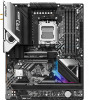
...1.2 Specifications 2 1.3 Motherboard Layout 7 1.4 I/O Panel 9 1.5 Block Diagram 11 1.6 802.11ax Wi-Fi 6E Module and ASRock WiFi 2.4/5/6 GHz Antenna 12 1.7 Graphics Card Holder 13 Chapter 2 Installation 14 2.1 Installing the CPU 15 2.2 Installing the CPU Fan and Heatsink 18 2.3 Installing Memory Modules (DIMM) 27 2.4 Connecting the Front Panel Header 29 2.5 Installing the Motherboard 30 2.6 Installing SATA Drives 31 2.7 Installing a Graphics Card 33 2.8 Connecting Peripheral Devices 35 2.9 Connecting the Power Connectors 36 2.10 Power On 37 2.11 Jumpers Setup...
...1.2 Specifications 2 1.3 Motherboard Layout 7 1.4 I/O Panel 9 1.5 Block Diagram 11 1.6 802.11ax Wi-Fi 6E Module and ASRock WiFi 2.4/5/6 GHz Antenna 12 1.7 Graphics Card Holder 13 Chapter 2 Installation 14 2.1 Installing the CPU 15 2.2 Installing the CPU Fan and Heatsink 18 2.3 Installing Memory Modules (DIMM) 27 2.4 Connecting the Front Panel Header 29 2.5 Installing the Motherboard 30 2.6 Installing SATA Drives 31 2.7 Installing a Graphics Card 33 2.8 Connecting Peripheral Devices 35 2.9 Connecting the Power Connectors 36 2.10 Power On 37 2.11 Jumpers Setup...

User Manual
Page 9
X670E Pro RS Connector • 1 x SPI TPM Header • 1 x Power LED and Speaker Header • 1 x RGB LED Header* • 3 x Addressable LED Headers** • 1 x CPU Fan Connector (4-pin)*** • 1 x CPU/Water Pump Fan Connector (4-pin) (Smart Fan Speed Control)**** • 4 x Chassis/Water Pump Fan Connectors (4-pin) (Smart Fan Speed Control)***** • 1 x 24 pin ATX Power Connector (Hi-Density Power Connector) • 1 x 8 pin 12V Power Connector (Hi-Density Power Connector) • 1 x 4 pin 12V Power Connector (Hi-Density Power Connector) • 1 x Front Panel Audio ...
X670E Pro RS Connector • 1 x SPI TPM Header • 1 x Power LED and Speaker Header • 1 x RGB LED Header* • 3 x Addressable LED Headers** • 1 x CPU Fan Connector (4-pin)*** • 1 x CPU/Water Pump Fan Connector (4-pin) (Smart Fan Speed Control)**** • 4 x Chassis/Water Pump Fan Connectors (4-pin) (Smart Fan Speed Control)***** • 1 x 24 pin ATX Power Connector (Hi-Density Power Connector) • 1 x 8 pin 12V Power Connector (Hi-Density Power Connector) • 1 x 4 pin 12V Power Connector (Hi-Density Power Connector) • 1 x Front Panel Audio ...

User Manual
Page 60
... make sure that you have already stored and backup-ed the recovery key. Plug the 24 pin power connector to blink. 8. Otherwise an unpredictable failure may occur. ASRock BIOS Flashback feature allows you plug the USB drive to the USB BIOS Flashback port. **If the LED does not light up at all then please disconnect power from the system and remove/ disconnect the CMOS battery from the motherboard for about three seconds.
... make sure that you have already stored and backup-ed the recovery key. Plug the 24 pin power connector to blink. 8. Otherwise an unpredictable failure may occur. ASRock BIOS Flashback feature allows you plug the USB drive to the USB BIOS Flashback port. **If the LED does not light up at all then please disconnect power from the system and remove/ disconnect the CMOS battery from the motherboard for about three seconds.

User Manual
Page 65
X670E Pro RS 2.16 M.2 SSD Module Installation Guide (M2_2) The M.2 is a small size and versatile card edge connector that aims to be used. B A No. Installing the M.2 SSD Module Step 1 Prepare a M.2 SSD module and the screw. 2 Step 2 1 Depending on the PCB type and length of your M.2 SSD module, find the corresponding nut location to replace mPCIe and mSATA. The Hyper M.2 Socket (M2_2, Key M) supports type 2260/2280 PCIe Gen4x4 (64 Gb/s) mode. Nut Location PCB Length Module Type 1 A 6cm Type 2260 2 B 8cm Type 2280 61
X670E Pro RS 2.16 M.2 SSD Module Installation Guide (M2_2) The M.2 is a small size and versatile card edge connector that aims to be used. B A No. Installing the M.2 SSD Module Step 1 Prepare a M.2 SSD module and the screw. 2 Step 2 1 Depending on the PCB type and length of your M.2 SSD module, find the corresponding nut location to replace mPCIe and mSATA. The Hyper M.2 Socket (M2_2, Key M) supports type 2260/2280 PCIe Gen4x4 (64 Gb/s) mode. Nut Location PCB Length Module Type 1 A 6cm Type 2260 2 B 8cm Type 2280 61

User Manual
Page 67
Nut Location PCB Length Module Type 1 A 6cm Type 2260 2 B 8cm Type 2280 63 The Hyper M.2 Sockets (M2_3 and M2_5, Key M) support type 2260/2280 PCIe Gen4x4 (64 Gb/s) mode. Step 2 2 1 Depending on the PCB type and length of your M.2 SSD module, find the corresponding nut location to replace mPCIe and mSATA. X670E Pro RS 2.17 M.2 SSD Module Installation Guide (M2_3 and M2_5) The M.2 is a small size and versatile card edge connector that aims to be used. B A No. Installing the M.2 SSD Module Step 1 Prepare a M.2 SSD module and the screw.
Nut Location PCB Length Module Type 1 A 6cm Type 2260 2 B 8cm Type 2280 63 The Hyper M.2 Sockets (M2_3 and M2_5, Key M) support type 2260/2280 PCIe Gen4x4 (64 Gb/s) mode. Step 2 2 1 Depending on the PCB type and length of your M.2 SSD module, find the corresponding nut location to replace mPCIe and mSATA. X670E Pro RS 2.17 M.2 SSD Module Installation Guide (M2_3 and M2_5) The M.2 is a small size and versatile card edge connector that aims to be used. B A No. Installing the M.2 SSD Module Step 1 Prepare a M.2 SSD module and the screw.


