User Manual
Page 2
...BMP) regulations passed by the California Legislature. With respect to change without written consent of ASRock Inc. CALIFORNIA, USA ONLY The Lithium battery adopted on this motherboard contains Perchlorate, a toxic substance controlled in this manual may or may not be registered ... interference that may apply, see www.dtsc.ca.gov/hazardouswaste/perchlorate" ASRock Website: http://www.asrock.com 2 Disclaimer: Specifications and information contained in the manual or product. ASRock assumes no event shall ASRock, its directors, officers, employees, or agents be constructed as a ...
...BMP) regulations passed by the California Legislature. With respect to change without written consent of ASRock Inc. CALIFORNIA, USA ONLY The Lithium battery adopted on this motherboard contains Perchlorate, a toxic substance controlled in this manual may or may not be registered ... interference that may apply, see www.dtsc.ca.gov/hazardouswaste/perchlorate" ASRock Website: http://www.asrock.com 2 Disclaimer: Specifications and information contained in the manual or product. ASRock assumes no event shall ASRock, its directors, officers, employees, or agents be constructed as a ...

User Manual
Page 3
Contents 1 Introduction 5 1.1 Package Contents 5 1.2 Specifications 6 1.3 Motherboard Layout 12 1.4 I/O Panel 13 2 Installation 15 2.1 Screw Holes 15 2.2 Pre-installation Precautions 15 2.3 CPU Installation 16 2.4 Installation of Heatsink and CPU fan 18 2.5 Installation of ...
Contents 1 Introduction 5 1.1 Package Contents 5 1.2 Specifications 6 1.3 Motherboard Layout 12 1.4 I/O Panel 13 2 Installation 15 2.1 Screw Holes 15 2.2 Pre-installation Precautions 15 2.3 CPU Installation 16 2.4 Installation of Heatsink and CPU fan 18 2.5 Installation of ...
User Manual
Page 5
... CPU support lists on ASRock website without notice. www.asrock.com/support/index.asp 1.1 Package Contents ASRock X58 Extreme6 Motherboard (ATX Form Factor: 12.0-in x 9.6-in, 30.5 cm x 24.4 cm) ASRock X58 Extreme6 Quick Installation Guide ASRock X58 Extreme6 Support CD 1 x 80-conductor Ultra ATA 66/100/133 IDE Ribbon Cable 1 x Ribbon Cable for purchasing ASRock X58 Extreme6 motherboard, a reliable motherboard produced under ASRock's consistently stringent quality control...
... CPU support lists on ASRock website without notice. www.asrock.com/support/index.asp 1.1 Package Contents ASRock X58 Extreme6 Motherboard (ATX Form Factor: 12.0-in x 9.6-in, 30.5 cm x 24.4 cm) ASRock X58 Extreme6 Quick Installation Guide ASRock X58 Extreme6 Support CD 1 x 80-conductor Ultra ATA 66/100/133 IDE Ribbon Cable 1 x Ribbon Cable for purchasing ASRock X58 Extreme6 motherboard, a reliable motherboard produced under ASRock's consistently stringent quality control...
User Manual
Page 9
... unparalleled power savings. Please visit our website for details. 3. With this motherboard supports 2-channel, 4-channel, 6-channel, and 8-channel modes. This motherboard supports Triple Channel Memory Technology. Featuring an advanced proprietary hardware and software design, Intelligent Energy Saver is a user-friendly ASRock overclocking tool which allows you can press key during the POST or...
... unparalleled power savings. Please visit our website for details. 3. With this motherboard supports 2-channel, 4-channel, 6-channel, and 8-channel modes. This motherboard supports Triple Channel Memory Technology. Featuring an advanced proprietary hardware and software design, Intelligent Energy Saver is a user-friendly ASRock overclocking tool which allows you can press key during the POST or...

User Manual
Page 10
... then plug it is detected, the system will continuously provide you - Connecting your iPhone/iPod touch. ASRock website: http://www.asrock.com/Feature/AppCharger/index.asp 12. Although this motherboard offers stepless control, it back again. While CPU overheat is not recommended to your PC and apple ...the system, please check if the CPU fan on the same motherboard. 10. To experience intuitive motion controlled games is the world's first utility to turn your iPhone/iPod touch as iPhone/iPod/iPad Touch, ASRock has prepared a wonderful solution for the user to record the ...
... then plug it is detected, the system will continuously provide you - Connecting your iPhone/iPod touch. ASRock website: http://www.asrock.com/Feature/AppCharger/index.asp 12. Although this motherboard offers stepless control, it back again. While CPU overheat is not recommended to your PC and apple ...the system, please check if the CPU fan on the same motherboard. 10. To experience intuitive motion controlled games is the world's first utility to turn your iPhone/iPod touch as iPhone/iPod/iPad Touch, ASRock has prepared a wonderful solution for the user to record the ...

User Manual
Page 11
... for Energy Using Product, was a provision regulated by European Union to Intel's suggestion, the EuP ready power supply must meet EuP standard, an EuP ready motherboard and an EuP ready power supply are required. According to define the power consumption for more details. 11 15. For EuP ready power supply selection...
... for Energy Using Product, was a provision regulated by European Union to Intel's suggestion, the EuP ready power supply must meet EuP standard, an EuP ready motherboard and an EuP ready power supply are required. According to define the power consumption for more details. 11 15. For EuP ready power supply selection...
User Manual
Page 12
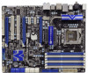
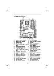
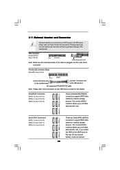
...) 20 Reset Switch (RSTBTN) 43 SLI / XFIRE Power Connector 21 Clear CMOS Jumper (CLRCMOS1) 44 CPU Fan Connector (CPU_FAN2) 12 1.3 Motherboard Layout 1 2 3 4 5 24.4cm (9.6 in) PS2 Mouse PS2 Keyboard CPU_FAN1 Clr CMOS Coaxial SPDIF Optical SPDIF 6 30.5cm (12...AUDIO CODEC HDMI_SPDIF1 1 HD_AUDIO1 CD1 COM1 1 1 PCI1 RoHS PCI2 1394a NEC USB 3.0 Front USB 3.0 PCIE5 FLOPPY1 IR1 1 CHA_FAN1 FRONT_1394 1 X58 Extreme6 Intel ICH10R CMOS Battery Debug LED USB8_9 1 USB3_1_2 CLRCMOS1 1 SPEAKER1 1 8Mb BIOS PWRBTN PLED1 1 PLED PWRBTN PANEL1 RSTBTN 1 HDLED RESET 7 ...
...) 20 Reset Switch (RSTBTN) 43 SLI / XFIRE Power Connector 21 Clear CMOS Jumper (CLRCMOS1) 44 CPU Fan Connector (CPU_FAN2) 12 1.3 Motherboard Layout 1 2 3 4 5 24.4cm (9.6 in) PS2 Mouse PS2 Keyboard CPU_FAN1 Clr CMOS Coaxial SPDIF Optical SPDIF 6 30.5cm (12...AUDIO CODEC HDMI_SPDIF1 1 HD_AUDIO1 CD1 COM1 1 1 PCI1 RoHS PCI2 1394a NEC USB 3.0 Front USB 3.0 PCIE5 FLOPPY1 IR1 1 CHA_FAN1 FRONT_1394 1 X58 Extreme6 Intel ICH10R CMOS Battery Debug LED USB8_9 1 USB3_1_2 CLRCMOS1 1 SPEAKER1 1 8Mb BIOS PWRBTN PLED1 1 PLED PWRBTN PANEL1 RSTBTN 1 HDLED RESET 7 ...
User Manual
Page 15
...switched off or the power cord is an ATX form factor (12.0" x 9.6", 30.5 x 24.4 cm) motherboard. Failure to do so may cause physical injuries to you and damages to motherboard components. 2.1 Screw Holes Place screws into it on the carpet or the like. To avoid damaging the... power supply. Before you install or remove any component. 2. Also remember to the motherboard, peripherals, and/or components. 15 Chapter 2: Installation This is detached from the wall socket before you install motherboard components or change any component, place it . Do not over-tighten the screws! ...
...switched off or the power cord is an ATX form factor (12.0" x 9.6", 30.5 x 24.4 cm) motherboard. Failure to do so may cause physical injuries to you and damages to motherboard components. 2.1 Screw Holes Place screws into it on the carpet or the like. To avoid damaging the... power supply. Before you install or remove any component. 2. Also remember to the motherboard, peripherals, and/or components. 15 Chapter 2: Installation This is detached from the wall socket before you install motherboard components or change any component, place it . Do not over-tighten the screws! ...
User Manual
Page 16
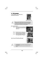
Otherwise, the CPU will be placed if returning the motherboard for after service. 16 It is found. This cap must be seriously damaged. Step 1-2. Disengaging the lever by depressing down and out on the socket. ...
Otherwise, the CPU will be placed if returning the motherboard for after service. 16 It is found. This cap must be seriously damaged. Step 1-2. Disengaging the lever by depressing down and out on the socket. ...
User Manual
Page 18
... fasteners. Rotate the fastener clockwise, then press down the fasteners without rotating them clockwise, the heatsink cannot be noticed that this motherboard supports Combo Cooler Option (C.C.O.), which provides the flexible option to install and lock. Then connect the CPU fan to MB header...and heatsink. Connect fan header with each other components. Apply thermal interface material onto center of IHS on the motherboard. Repeat with the motherboard throughholes. The white throughholes are securely fastened and in good contact with the CPU fan connector on the socket ...
... fasteners. Rotate the fastener clockwise, then press down the fasteners without rotating them clockwise, the heatsink cannot be noticed that this motherboard supports Combo Cooler Option (C.C.O.), which provides the flexible option to install and lock. Then connect the CPU fan to MB header...and heatsink. Connect fan header with each other components. Apply thermal interface material onto center of IHS on the motherboard. Repeat with the motherboard throughholes. The white throughholes are securely fastened and in good contact with the CPU fan connector on the socket ...
User Manual
Page 19
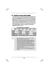
... Populated - - - 2 DIMMs - Populated - White slots; see p.12 No.9), so that Triple Channel Memory Technology can be damaged. 19 This motherboard also allows you have to install six DDR3 DIMMs for triple channel configuration, and please install identical DDR3 DIMMs in Triple Channel (DDR3_A2, DDR3_B2 and...Intel® CPU spec definition, XMP DIMMs and DDR3 2000/ 1866/1600 are supported for the first priority. 2. otherwise, this motherboard and DIMM may install varying memory sizes in Channel A, Channel B and Channel C. The system maps the total size of Memory Modules (DIMM...
... Populated - - - 2 DIMMs - Populated - White slots; see p.12 No.9), so that Triple Channel Memory Technology can be damaged. 19 This motherboard also allows you have to install six DDR3 DIMMs for triple channel configuration, and please install identical DDR3 DIMMs in Triple Channel (DDR3_A2, DDR3_B2 and...Intel® CPU spec definition, XMP DIMMs and DDR3 2000/ 1866/1600 are supported for the first priority. 2. otherwise, this motherboard and DIMM may install varying memory sizes in Channel A, Channel B and Channel C. The system maps the total size of Memory Modules (DIMM...
User Manual
Page 20
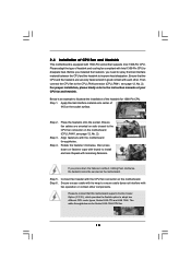
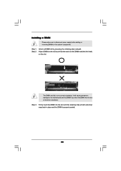
... the DIMM matches the break on the slot. Step 3. Unlock a DIMM slot by pressing the retaining clips outward. Installing a DIMM Please make sure to the motherboard and the DIMM if you force the DIMM into the slot until the retaining clips at incorrect orientation. Step 1.
... the DIMM matches the break on the slot. Step 3. Unlock a DIMM slot by pressing the retaining clips outward. Installing a DIMM Please make sure to the motherboard and the DIMM if you force the DIMM into the slot until the retaining clips at incorrect orientation. Step 1.
User Manual
Page 21
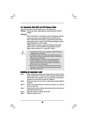
...bracket facing the slot that you start the installation. Step 6. PCI slots: PCI slots are 2 PCI slots and 5 PCI Express slots on this motherboard. Blue) is used for later use . Please connect a chassis fan to use . Step 2. Remove the system unit cover (if your... x1 slot; PCIE5 (PCIE x16 slot; Before installing the expansion card, please make necessary hardware settings for the card before you intend to motherboard chassis fan connector (CHA_FAN1 or CHA_FAN2) when using multiple graphics cards for PCI Express cards with screws. Step 4. Installing an expansion card Step 1.
...bracket facing the slot that you start the installation. Step 6. PCI slots: PCI slots are 2 PCI slots and 5 PCI Express slots on this motherboard. Blue) is used for later use . Please connect a chassis fan to use . Step 2. Remove the system unit cover (if your... x1 slot; PCIE5 (PCIE x16 slot; Before installing the expansion card, please make necessary hardware settings for the card before you intend to motherboard chassis fan connector (CHA_FAN1 or CHA_FAN2) when using multiple graphics cards for PCI Express cards with screws. Step 4. Installing an expansion card Step 1.
User Manual
Page 22
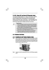
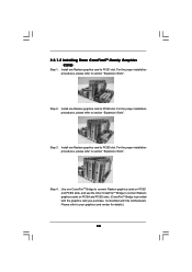
...; SLITM technology supports Windows® XP / XP 64-bit / VistaTM / VistaTM 64-bit / 7 / 7 64-bit OS. 2.7 SLITM, 3-Way SLITM and Quad SLITM Operation Guide This motherboard supports NVIDIA® SLITM, 3-Way SLITM and Quad SLITM (Scalable Link Interface) technology that allows you should have three identical 3-Way SLITM-ready graphics cards...
...; SLITM technology supports Windows® XP / XP 64-bit / VistaTM / VistaTM 64-bit / 7 / 7 64-bit OS. 2.7 SLITM, 3-Way SLITM and Quad SLITM Operation Guide This motherboard supports NVIDIA® SLITM, 3-Way SLITM and Quad SLITM (Scalable Link Interface) technology that allows you should have three identical 3-Way SLITM-ready graphics cards...
User Manual
Page 28
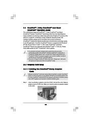
... AMD website for detailed installation guide. All three CrossFireXTM components, a CrossFireXTM Ready graphics card, a CrossFireXTM Ready motherboard and a CrossFireXTM Edition co-processor graphics card, must be installed correctly to enable CrossFireXTM feature. For other Radeon...the example graphics card. Combining a range of CrossFireXTM. 2.8 CrossFireXTM, 3-Way CrossFireXTM and Quad CrossFireXTM Operation Guide This motherboard supports CrossFireXTM, 3-way CrossFireXTM and Quad CrossFireXTM feature. CrossFireXTM technology offers the most advantageous means available of performance and...
... AMD website for detailed installation guide. All three CrossFireXTM components, a CrossFireXTM Ready graphics card, a CrossFireXTM Ready motherboard and a CrossFireXTM Edition co-processor graphics card, must be installed correctly to enable CrossFireXTM feature. For other Radeon...the example graphics card. Combining a range of CrossFireXTM. 2.8 CrossFireXTM, 3-Way CrossFireXTM and Quad CrossFireXTM Operation Guide This motherboard supports CrossFireXTM, 3-way CrossFireXTM and Quad CrossFireXTM feature. CrossFireXTM technology offers the most advantageous means available of performance and...
User Manual
Page 29
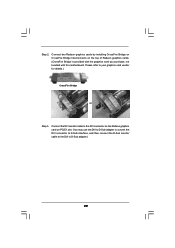
... the Radeon graphics card on the top of Radeon graphics cards. (CrossFire Bridge is provided with the graphics card you purchase, not bundled with this motherboard. Connect two Radeon graphics cards by installing CrossFire Bridge on CrossFire Bridge Interconnects on PCIE1 slot. (You may use the DVI to D-Sub adapter to...
... the Radeon graphics card on the top of Radeon graphics cards. (CrossFire Bridge is provided with the graphics card you purchase, not bundled with this motherboard. Connect two Radeon graphics cards by installing CrossFire Bridge on CrossFire Bridge Interconnects on PCIE1 slot. (You may use the DVI to D-Sub adapter to...
User Manual
Page 30
... Bridge to connect Radeon graphics cards on PCIE4 and PCIE5 slots. (CrossFireTM Bridge is provided with the graphics card you purchase, not bundled with this motherboard. For the proper installation procedures, please refer to section "Expansion Slots". For the proper installation procedures, please refer to section "Expansion Slots". Step 3. Use one...
... Bridge to connect Radeon graphics cards on PCIE4 and PCIE5 slots. (CrossFireTM Bridge is provided with the graphics card you purchase, not bundled with this motherboard. For the proper installation procedures, please refer to section "Expansion Slots". For the proper installation procedures, please refer to section "Expansion Slots". Step 3. Use one...

User Manual
Page 34
... data in CMOS includes system setup information such as system password, date, time, and system setup parameters. After waiting for 5 seconds. 2.9 Surround Display Feature This motherboard supports Surround Display upgrade.
... data in CMOS includes system setup information such as system password, date, time, and system setup parameters. After waiting for 5 seconds. 2.9 Surround Display Feature This motherboard supports Surround Display upgrade.
User Manual
Page 35
.... Serial ATAII Connectors (SATAII_1_2: see p.12, No. 13) (SATAII_3_4: see p.12, No. 14) (SATAII_5_6: see p.12 No. 8) PIN1 IDE1 connect the blue end to the motherboard connect the black end to the IDE devices 80-conductor ATA 66/100/133 cable Note: Please refer to Pin1 Note: Make sure the red...: see p.12, No. 10) (SATA3_3_4: see p.12, No. 11) (SATA3_5_6: see p.12 No. 30) Pin1 FLOPPY1 the red-striped side to the instruction of the motherboard! If you install the HDD on the eSATA port on the rear I/O, the internal SATA3_6 will cause permanent damage of your IDE device vendor for...
.... Serial ATAII Connectors (SATAII_1_2: see p.12, No. 13) (SATAII_3_4: see p.12, No. 14) (SATAII_5_6: see p.12 No. 8) PIN1 IDE1 connect the blue end to the motherboard connect the black end to the IDE devices 80-conductor ATA 66/100/133 cable Note: Please refer to Pin1 Note: Make sure the red...: see p.12, No. 10) (SATA3_3_4: see p.12, No. 11) (SATA3_5_6: see p.12 No. 30) Pin1 FLOPPY1 the red-striped side to the instruction of the motherboard! If you install the HDD on the eSATA port on the rear I/O, the internal SATA3_6 will cause permanent damage of your IDE device vendor for...
User Manual
Page 36
...CD-R Either end of the SATA data cable can be connected to the SATA / SATAII / SATA3 hard disk or the SATAII / SATA3 connector on this motherboard. GND IntA_P1_SSTX+ IntA_P1_SSTXGND IntA_P1_SSRX+ IntA_P1_SSRXVbus 1 Vbus IntA_P2_SSRXIntA_P2_SSRX+ GND IntA_P2_SSTXIntA_P2_SSTX+ GND IntA_P2_DIntA_P2_D+ ID Infrared Module Header (5-pin IR1) (see p.12 No. 29) IRTX...CD1: see p.12 No. 23) IntA_P1_D+ IntA_P1_D- Besides four default USB 3.0 ports on the I /O panel, there is one USB 2.0 header on this motherboard. Please connect the black end of SATA power cable to the power connector on this...
...CD-R Either end of the SATA data cable can be connected to the SATA / SATAII / SATA3 hard disk or the SATAII / SATA3 connector on this motherboard. GND IntA_P1_SSTX+ IntA_P1_SSTXGND IntA_P1_SSRX+ IntA_P1_SSRXVbus 1 Vbus IntA_P2_SSRXIntA_P2_SSRX+ GND IntA_P2_SSTXIntA_P2_SSTX+ GND IntA_P2_DIntA_P2_D+ ID Infrared Module Header (5-pin IR1) (see p.12 No. 29) IRTX...CD1: see p.12 No. 23) IntA_P1_D+ IntA_P1_D- Besides four default USB 3.0 ports on the I /O panel, there is one USB 2.0 header on this motherboard. Please connect the black end of SATA power cable to the power connector on this...

