
Quick Installation Guide
Page 8
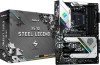
... be subject to quality and endurance. It delivers excellent performance with robust design conforming to ASRock's commitment to change without further notice. ASRock website http://www.asrock.com. 1.1 Package Contents • ASRock X570 Steel LegendMotherboard (ATX Form Factor) • ASRock X570 Steel LegendQuick Installation Guide • ASRock X570 Steel LegendSupport CD • 4 x Serial ATA (SATA) Data Cables (Optional) • 3 x Screws for M.2 Socket (Optional...
... be subject to quality and endurance. It delivers excellent performance with robust design conforming to ASRock's commitment to change without further notice. ASRock website http://www.asrock.com. 1.1 Package Contents • ASRock X570 Steel LegendMotherboard (ATX Form Factor) • ASRock X570 Steel LegendQuick Installation Guide • ASRock X570 Steel LegendSupport CD • 4 x Serial ATA (SATA) Data Cables (Optional) • 3 x Screws for M.2 Socket (Optional...
Quick Installation Guide
Page 10
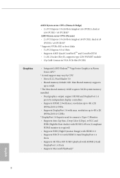
... • Supports 4K Ultra HD (UHD) playback with max. Max Shared memory supports up to 16GB. * The Max shared memory 16GB requires 32GB system memory installed. • Dual graphics output: support HDMI and DisplayPort 1.4 ports by CPU • DirectX 12, Pixel Shader 5.0 • Shared memory default 2GB. resolution up to 4K...
... • Supports 4K Ultra HD (UHD) playback with max. Max Shared memory supports up to 16GB. * The Max shared memory 16GB requires 32GB system memory installed. • Dual graphics output: support HDMI and DisplayPort 1.4 ports by CPU • DirectX 12, Pixel Shader 5.0 • Shared memory default 2GB. resolution up to 4K...

Quick Installation Guide
Page 15
... your chassis to ensure that comes with the components. • When placing screws to secure the motherboard to unplug the power cord before installing or removing the motherboard. X570 Steel Legend Chapter 2 Installation This is an ATX form factor motherboard. Also remember to use a grounded wrist strap or touch a safety grounded object before you and...
... your chassis to ensure that comes with the components. • When placing screws to secure the motherboard to unplug the power cord before installing or removing the motherboard. X570 Steel Legend Chapter 2 Installation This is an ATX form factor motherboard. Also remember to use a grounded wrist strap or touch a safety grounded object before you and...

Quick Installation Guide
Page 16
2.1 Installing the CPU Unplug all power cables before installing the CPU. 1 2 14 English
2.1 Installing the CPU Unplug all power cables before installing the CPU. 1 2 14 English

Quick Installation Guide
Page 18
Please turn off the power or remove the power cord before changing a CPU or heatsink. Installing the CPU Box Cooler SR1 1 2 16 English 2.2 Installing the CPU Fan and Heatsink After you install the CPU into this motherboard, it is necessary to install a larger heatsink and cooling fan to improve heat dissipation. You also need to spray thermal grease between the CPU and the heatsink to dissipate heat. Make sure that the CPU and the heatsink are securely fastened and in good contact with each other.
Please turn off the power or remove the power cord before changing a CPU or heatsink. Installing the CPU Box Cooler SR1 1 2 16 English 2.2 Installing the CPU Fan and Heatsink After you install the CPU into this motherboard, it is necessary to install a larger heatsink and cooling fan to improve heat dissipation. You also need to spray thermal grease between the CPU and the heatsink to dissipate heat. Make sure that the CPU and the heatsink are securely fastened and in good contact with each other.

Quick Installation Guide
Page 20
Installing the AM4 Box Cooler SR2 1 2 18 English
Installing the AM4 Box Cooler SR2 1 2 18 English

Quick Installation Guide
Page 23
Installing the AM4 Box Cooler SR3 1 X570 Steel Legend 2 21 English
Installing the AM4 Box Cooler SR3 1 X570 Steel Legend 2 21 English

Quick Installation Guide
Page 26
If you select AMD_FAN_LED1, please install ASRock utility "ASRock Polychrome SYNC". The headers might be used at a time in a different position on your motherboard. If you select USB connector, please install AMD utility "SR3 Settings Software". *The diagrams shown here are for the orientation of AMD Fan LED Header (AMD_FAN_LED1) and page 31 for reference only. Please refer to page 35 for the orientation of AMD LED Fan USB Header (USB_5). 24 English 6 CPU_FAN1 +12V RGB_LED2 or 7 CPU_FAN1 AMD_FAN_LED1 USB_5 Please note that only one cable should be in this step.
If you select AMD_FAN_LED1, please install ASRock utility "ASRock Polychrome SYNC". The headers might be used at a time in a different position on your motherboard. If you select USB connector, please install AMD utility "SR3 Settings Software". *The diagrams shown here are for the orientation of AMD Fan LED Header (AMD_FAN_LED1) and page 31 for reference only. Please refer to page 35 for the orientation of AMD LED Fan USB Header (USB_5). 24 English 6 CPU_FAN1 +12V RGB_LED2 or 7 CPU_FAN1 AMD_FAN_LED1 USB_5 Please note that only one cable should be in this step.

Quick Installation Guide
Page 27
... and DDR4_B2 first for better DRAM compatibility on 2 DIMMs configuration. SR - - 3200 - DR - SR - SR - - 2933 - SR - X570 Steel Legend 2.3 Installing Memory Modules (DIMM) This motherboard provides four 288-pin DDR4 (Double Data Rate 4) DIMM slots, and supports Dual Channel Memory Technology. 1. DR - ...- 3200 - It is not allowed to activate Dual Channel Memory Technology with only one or three memory module installed. 3. It is unable to install a DDR, DDR2 or DDR3 memory module into a DDR4 slot; DR 3200 SR SR SR SR 2933 SR/DR DR ...
... and DDR4_B2 first for better DRAM compatibility on 2 DIMMs configuration. SR - - 3200 - DR - SR - SR - - 2933 - SR - X570 Steel Legend 2.3 Installing Memory Modules (DIMM) This motherboard provides four 288-pin DDR4 (Double Data Rate 4) DIMM slots, and supports Dual Channel Memory Technology. 1. DR - ...- 3200 - It is not allowed to activate Dual Channel Memory Technology with only one or three memory module installed. 3. It is unable to install a DDR, DDR2 or DDR3 memory module into a DDR4 slot; DR 3200 SR SR SR SR 2933 SR/DR DR ...
Quick Installation Guide
Page 30
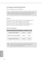
... expansion card and make sure that the power supply is switched off or the power cord is used for the card before you start the installation. Before installing an expansion card, please make necessary hardware settings for PCI Express x1 lane width cards. English 28
... expansion card and make sure that the power supply is switched off or the power cord is used for the card before you start the installation. Before installing an expansion card, please make necessary hardware settings for PCI Express x1 lane width cards. English 28
Quick Installation Guide
Page 34
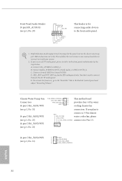
...1 cooling chassis fan connectors. E. If you plan to connect a 3-Pin chassis GND FAN_VOLTAGE water cooler fan, please FAN_SPEED FAN_SPEED_CONTROL connect it to install your system. 2. To activate the front mic, go to the "FrontMic" Tab in our manual and chassis manual to the front panel audio... (LIN) to MIC2_L. MIC_RET and OUT_RET are for the HD audio panel only. D. If you use an AC'97 audio panel, please install it to the front audio panel. 1. Please follow the instructions in the Realtek Control panel and adjust "Recording Volume". C. B. Chassis Water Pump...
...1 cooling chassis fan connectors. E. If you plan to connect a 3-Pin chassis GND FAN_VOLTAGE water cooler fan, please FAN_SPEED FAN_SPEED_CONTROL connect it to install your system. 2. To activate the front mic, go to the "FrontMic" Tab in our manual and chassis manual to the front panel audio... (LIN) to MIC2_L. MIC_RET and OUT_RET are for the HD audio panel only. D. If you use an AC'97 audio panel, please install it to the front audio panel. 1. Please follow the instructions in the Realtek Control panel and adjust "Recording Volume". C. B. Chassis Water Pump...
Quick Installation Guide
Page 36
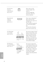
... fits into this connector in card (AIC) to the Thunderbolt AIC connector via the GPIO cable. *Please install the Thunderbolt™ AIC card to PCIE4 (default slot). *For the further information, please visit www.asrock.com. A TPM system also helps enhance network security, protects digital identities, and ensures platform integrity. LPC/TPM...
... fits into this connector in card (AIC) to the Thunderbolt AIC connector via the GPIO cable. *Please install the Thunderbolt™ AIC card to PCIE4 (default slot). *For the further information, please visit www.asrock.com. A TPM system also helps enhance network security, protects digital identities, and ensures platform integrity. LPC/TPM...

Quick Installation Guide
Page 37
... from various LED lighting effects. This header is used to connect Addressable LED extension cable which allows users to choose from various LED lighting effects. X570 Steel Legend AMD FAN LED Header (4-pin AMD_FAN_ LED1) (see p.1, No. 7) 1 B R G 12V RGB LED Header (4-pin RGB_HEADER1) (see p.1, No. 24) 1 12V G... to connect RGB LED extension cable that comes with a regular RGB LED stripe. Caution: Never install the FAN LED cable in the wrong orientation; Caution: Never install the Addressable LED cable in the wrong orientation; otherwise, the cable may be damaged. *Please ...
... from various LED lighting effects. This header is used to connect Addressable LED extension cable which allows users to choose from various LED lighting effects. X570 Steel Legend AMD FAN LED Header (4-pin AMD_FAN_ LED1) (see p.1, No. 7) 1 B R G 12V RGB LED Header (4-pin RGB_HEADER1) (see p.1, No. 24) 1 12V G... to connect RGB LED extension cable that comes with a regular RGB LED stripe. Caution: Never install the FAN LED cable in the wrong orientation; Caution: Never install the Addressable LED cable in the wrong orientation; otherwise, the cable may be damaged. *Please ...
Quick Installation Guide
Page 39
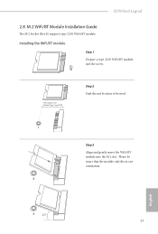
PCB Length: 3cm Module Type: Type2230 Step 2 Find the nut location to be aware that the module only fits in one orientation. English A 20o 37 Please be used. Installing the WiFi/BT module Step 1 Prepare a type 2230 WiFi/BT module and the screw. A A Step 3 Align and gently insert the WiFi/BT module into the M.2 slot. X570 Steel Legend 2.8 M.2 WiFi/BT Module Installation Guide The M.2 Socket (Key E) supports type 2230 WiFi/BT module.
PCB Length: 3cm Module Type: Type2230 Step 2 Find the nut location to be aware that the module only fits in one orientation. English A 20o 37 Please be used. Installing the WiFi/BT module Step 1 Prepare a type 2230 WiFi/BT module and the screw. A A Step 3 Align and gently insert the WiFi/BT module into the M.2 slot. X570 Steel Legend 2.8 M.2 WiFi/BT Module Installation Guide The M.2 Socket (Key E) supports type 2230 WiFi/BT module.

Quick Installation Guide
Page 41
D C B A No. X570 Steel Legend 2.9 M.2_SSD (NGFF) Module Installation Guide (M2_1) The M.2, also known as the Next Generation Form Factor (NGFF), is a small size and versatile card edge connector that aims to Gen4x4 (64 ... Type2260 4 D 8cm Type 2280 English 39 The M.2 Socket (M2_2) supports M Key type 2230/2242/2260/2280 M.2 PCI Express module up to replace mPCIe and mSATA. Installing the M.2_SSD (NGFF) Module Step 1 Prepare a M.2_SSD (NGFF) module and the screw. 4 3 2 1 Step 2 Depending on the PCB type and length of your M.2_SSD (NGFF) module...
D C B A No. X570 Steel Legend 2.9 M.2_SSD (NGFF) Module Installation Guide (M2_1) The M.2, also known as the Next Generation Form Factor (NGFF), is a small size and versatile card edge connector that aims to Gen4x4 (64 ... Type2260 4 D 8cm Type 2280 English 39 The M.2 Socket (M2_2) supports M Key type 2230/2242/2260/2280 M.2 PCI Express module up to replace mPCIe and mSATA. Installing the M.2_SSD (NGFF) Module Step 1 Prepare a M.2_SSD (NGFF) module and the screw. 4 3 2 1 Step 2 Depending on the PCB type and length of your M.2_SSD (NGFF) module...

Quick Installation Guide
Page 42
Then hand tighten the standoff into the desired nut location on the bottom side of the M.2 heatsink before you install a M.2 SSD module. Please do not overtighten the screw as this might damage the module. Please be aware that comes with a screwdriver to remove the M.2 heatsink. *... NUT1 40 Step 4 Prepare the M.2 standoff that the M.2 (NGFF) SSD module only fits in one orientation. Step 5 Tighten the screw with the package. 2 1 1 Step 3 Before installing a M.2 (NGFF) SSD 1 module, please loosen the screws to secure the module into the M.2 slot. English
Then hand tighten the standoff into the desired nut location on the bottom side of the M.2 heatsink before you install a M.2 SSD module. Please do not overtighten the screw as this might damage the module. Please be aware that comes with a screwdriver to remove the M.2 heatsink. *... NUT1 40 Step 4 Prepare the M.2 standoff that the M.2 (NGFF) SSD module only fits in one orientation. Step 5 Tighten the screw with the package. 2 1 1 Step 3 Before installing a M.2 (NGFF) SSD 1 module, please loosen the screws to secure the module into the M.2 slot. English

Quick Installation Guide
Page 44
...3cm Type2230 2 B 4.2cm Type 2242 3 C 6cm Type2260 4 D 8cm Type 2280 5 E 11cm Type 22110 English 42 2.10 M.2_SSD (NGFF) Module Installation Guide (M2_2) The M.2, also known as the Next Generation Form Factor (NGFF), is a small size and versatile card edge connector that aims to Gen4x4 (64...Hyper M.2 Socket (M2_3) supports M Key type 2230/2242/2260/2280/22110 M.2 SATA3 6.0 Gb/s module and M.2 PCI Express module up to replace mPCIe and mSATA. Installing the M.2_SSD (NGFF) Module Step 1 Prepare a M.2_SSD (NGFF) module and the screw. 5 4 3 2 1 Step 2 Depending on the PCB type and ...
...3cm Type2230 2 B 4.2cm Type 2242 3 C 6cm Type2260 4 D 8cm Type 2280 5 E 11cm Type 22110 English 42 2.10 M.2_SSD (NGFF) Module Installation Guide (M2_2) The M.2, also known as the Next Generation Form Factor (NGFF), is a small size and versatile card edge connector that aims to Gen4x4 (64...Hyper M.2 Socket (M2_3) supports M Key type 2230/2242/2260/2280/22110 M.2 SATA3 6.0 Gb/s module and M.2 PCI Express module up to replace mPCIe and mSATA. Installing the M.2_SSD (NGFF) Module Step 1 Prepare a M.2_SSD (NGFF) module and the screw. 5 4 3 2 1 Step 2 Depending on the PCB type and ...

Quick Installation Guide
Page 45
.... E D C B A E D C B A 20o E D NUT2 NUT1 Step 4 Prepare the M.2 standoff that the M.2 (NGFF) SSD module only fits in one orientation. Step 5 Tighten the screw with the package. 2 1 1 X570 Steel Legend Step 3 Before installing a M.2 (NGFF) SSD 1 module, please loosen the screws to secure the module into place. Please do not overtighten the screw as this might damage the...
.... E D C B A E D C B A 20o E D NUT2 NUT1 Step 4 Prepare the M.2 standoff that the M.2 (NGFF) SSD module only fits in one orientation. Step 5 Tighten the screw with the package. 2 1 1 X570 Steel Legend Step 3 Before installing a M.2 (NGFF) SSD 1 module, please loosen the screws to secure the module into place. Please do not overtighten the screw as this might damage the...
Quick Installation Guide
Page 47
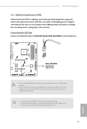
... to motherboard components. 1. otherwise, the cable may cause damages to the RGB LED Header (RGB_HEADER1) on the motherboard. Never install the RGB LED cable in the wrong orientation; The RGB LED header supports standard 5050 RGB LED strip (12V/G/R/B), with sophisticated...Cycling, Music, Wave and more. Connecting the LED Strip Connect your system and unplug the power cord from the power supply. X570 Steel Legend 2.11 ASRock Polychrome SYNC ASRock Polychrome SYNC is a lighting control utility specifically designed for unique individuals with a maximum power rating of 3A (12V) and ...
... to motherboard components. 1. otherwise, the cable may cause damages to the RGB LED Header (RGB_HEADER1) on the motherboard. Never install the RGB LED cable in the wrong orientation; The RGB LED header supports standard 5050 RGB LED strip (12V/G/R/B), with sophisticated...Cycling, Music, Wave and more. Connecting the LED Strip Connect your system and unplug the power cord from the power supply. X570 Steel Legend 2.11 ASRock Polychrome SYNC ASRock Polychrome SYNC is a lighting control utility specifically designed for unique individuals with a maximum power rating of 3A (12V) and ...
Quick Installation Guide
Page 48
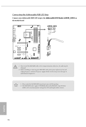
...VOUT 1 1. otherwise, the cable may cause damages to motherboard components. 1. Failure to the Addressable LED Header (ADDR_LED1) on the motherboard. Before installing or removing your RGB LED cable, please power off your Addressable RGB LED strip to do not come with a maximum power rating of 3A (5V... Please note that the RGB LED strips do so may be damaged. 2. X570 EXTREME4 Connecting the Addressable RGB LED Strip Connect your system and unplug the power cord from the power supply. Never install the RGB LED cable in the wrong orientation; The RGB LED header supports WS2812B...
...VOUT 1 1. otherwise, the cable may cause damages to motherboard components. 1. Failure to the Addressable LED Header (ADDR_LED1) on the motherboard. Before installing or removing your RGB LED cable, please power off your Addressable RGB LED strip to do not come with a maximum power rating of 3A (5V... Please note that the RGB LED strips do so may be damaged. 2. X570 EXTREME4 Connecting the Addressable RGB LED Strip Connect your system and unplug the power cord from the power supply. Never install the RGB LED cable in the wrong orientation; The RGB LED header supports WS2812B...


