RAID Installation Guide
Page 2
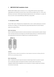
... hard disk drives into one drive fails. 2 Although RAID 0 function can start to use the onboard RAID Option ROM Utility to configure RAID. 1.1 Introduction to a second drive. Hot-Plug any fault tolerance. It provides data protection and increases fault tolerance to the entire system since it contains a complete copy of the same model and capacity when creating a RAID set the option to RAID mode by using the onboard FastBuild BIOS utility under BIOS environment. After you make a SATA driver...
... hard disk drives into one drive fails. 2 Although RAID 0 function can start to use the onboard RAID Option ROM Utility to configure RAID. 1.1 Introduction to a second drive. Hot-Plug any fault tolerance. It provides data protection and increases fault tolerance to the entire system since it contains a complete copy of the same model and capacity when creating a RAID set the option to RAID mode by using the onboard FastBuild BIOS utility under BIOS environment. After you make a SATA driver...
RAID Installation Guide
Page 8
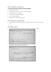
... RAID Installer F. During system boot, press or key to finish the driver copy process. A. B. E. Please download the "SATA Floppy Imaged driver" from ASRock's website A. Insert the Support CD into one of the USB port. STEP 3.2: Download driver from ASRock's website and unzip the file into your USB flash drive. 8 C. Click to find the driver inside your USB flash disk. D. Follow instructions to enter UEFI setup utility. During Windows installation process, when Disk selection page show up, please click . STEP 4: Windows installation A. Please install the DVD-ROM...
... RAID Installer F. During system boot, press or key to finish the driver copy process. A. B. E. Please download the "SATA Floppy Imaged driver" from ASRock's website A. Insert the Support CD into one of the USB port. STEP 3.2: Download driver from ASRock's website and unzip the file into your USB flash drive. 8 C. Click to find the driver inside your USB flash disk. D. Follow instructions to enter UEFI setup utility. During Windows installation process, when Disk selection page show up, please click . STEP 4: Windows installation A. Please install the DVD-ROM...
RAID Installation Guide
Page 12
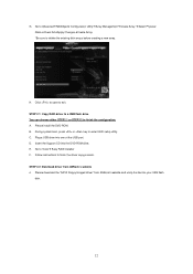
... sure to enter UEFI setup utility. A. During system boot, press or key to delete the existing disk arrays before creating a new array. STEP 2.2: Download driver from ASRock's website and unzip the file into your USB flash disk. 12 C. Plug a USB drive into the DVD-ROM drive. Click to save to finish the driver copy process. Please install the DVD-ROM. B. Insert the Support CD into one of the USB port. E. Please download the "SATA Floppy Imaged driver" from ASRock's website A. H. D. Follow instructions to...
... sure to enter UEFI setup utility. A. During system boot, press or key to delete the existing disk arrays before creating a new array. STEP 2.2: Download driver from ASRock's website and unzip the file into your USB flash disk. 12 C. Plug a USB drive into the DVD-ROM drive. Click to save to finish the driver copy process. Please install the DVD-ROM. B. Insert the Support CD into one of the USB port. E. Please download the "SATA Floppy Imaged driver" from ASRock's website A. H. D. Follow instructions to...
User Manual
Page 5
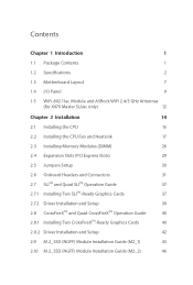
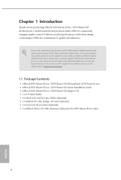
... Package Contents 1 1.2 Specifications 2 1.3 Motherboard Layout 7 1.4 I/O Panel 9 1.5 WiFi-802.11ac Module and ASRock WiFi 2.4/5 GHz Antennas (for X470 Master SLI/ac only) 12 Chapter 2 Installation 14 2.1 Installing the CPU 15 2.2 Installing the CPU Fan and Heatsink 17 2.3 Installing Memory Modules (DIMM) 26 2.4 Expansion Slots (PCI Express Slots) 29 2.5 Jumpers Setup 30 2.6 Onboard Headers and Connectors 31 2.7 SLITM and Quad SLITM Operation Guide 37 2.7.1 Installing Two SLITM-Ready Graphics Cards 37 2.7.2 Driver Installation and Setup 39 2.8 CrossFireXTM and...
... Package Contents 1 1.2 Specifications 2 1.3 Motherboard Layout 7 1.4 I/O Panel 9 1.5 WiFi-802.11ac Module and ASRock WiFi 2.4/5 GHz Antennas (for X470 Master SLI/ac only) 12 Chapter 2 Installation 14 2.1 Installing the CPU 15 2.2 Installing the CPU Fan and Heatsink 17 2.3 Installing Memory Modules (DIMM) 26 2.4 Expansion Slots (PCI Express Slots) 29 2.5 Jumpers Setup 30 2.6 Onboard Headers and Connectors 31 2.7 SLITM and Quad SLITM Operation Guide 37 2.7.1 Installing Two SLITM-Ready Graphics Cards 37 2.7.2 Driver Installation and Setup 39 2.8 CrossFireXTM and...
User Manual
Page 8
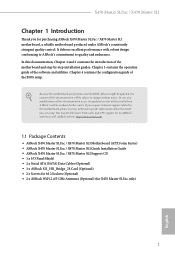
... Guide • ASRock X470 Master SLI/ac / X470 Master SLI Support CD • 1 x I/O Panel Shield • 2 x Serial ATA (SATA) Data Cables (Optional) • 1 x ASRock SLI_HB_Bridge_2S Card (Optional) • 2 x Screws for M.2 Sockets (Optional) • 2 x ASRock WiFi 2.4/5 GHz Antennas (Optional) (for purchasing ASRock X470 Master SLI/ac / X470 Master SLI motherboard, a reliable motherboard produced under ASRock's consistently stringent quality control. Chapter 4 contains the configuration guide of the software and utilities. In this documentation occur, the updated version...
... Guide • ASRock X470 Master SLI/ac / X470 Master SLI Support CD • 1 x I/O Panel Shield • 2 x Serial ATA (SATA) Data Cables (Optional) • 1 x ASRock SLI_HB_Bridge_2S Card (Optional) • 2 x Screws for M.2 Sockets (Optional) • 2 x ASRock WiFi 2.4/5 GHz Antennas (Optional) (for purchasing ASRock X470 Master SLI/ac / X470 Master SLI motherboard, a reliable motherboard produced under ASRock's consistently stringent quality control. Chapter 4 contains the configuration guide of the software and utilities. In this documentation occur, the updated version...
User Manual
Page 11
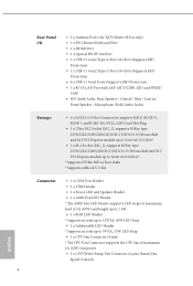
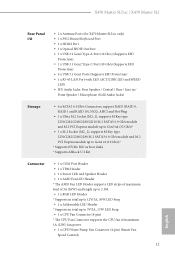
...X470 Master SLI/ac only) • 1 x PS/2 Mouse/Keyboard Port • 1 x HDMI Port • 1 x Optical SPDIF Out Port • 1 x USB 3.1 Gen2 Type-A Port (10 Gb/s) (Supports ESD Protection) • 1 x USB 3.1 Gen2 Type-C Port (10 Gb/s) (Supports ESD Protection) • 6 x USB 3.1 Gen1 Ports (Supports ESD Protection) • 1 x RJ-45 LAN Port with LED (ACT/LINK LED and SPEED LED) • HD Audio Jacks: Rear Speaker / Central / Bass / Line in / Front Speaker / Microphone (Gold Audio Jacks) Storage • 6 x SATA3 6.0 Gb/s Connectors, support RAID (RAID 0, RAID 1 and RAID 10), NCQ, AHCI...
...X470 Master SLI/ac only) • 1 x PS/2 Mouse/Keyboard Port • 1 x HDMI Port • 1 x Optical SPDIF Out Port • 1 x USB 3.1 Gen2 Type-A Port (10 Gb/s) (Supports ESD Protection) • 1 x USB 3.1 Gen2 Type-C Port (10 Gb/s) (Supports ESD Protection) • 6 x USB 3.1 Gen1 Ports (Supports ESD Protection) • 1 x RJ-45 LAN Port with LED (ACT/LINK LED and SPEED LED) • HD Audio Jacks: Rear Speaker / Central / Bass / Line in / Front Speaker / Microphone (Gold Audio Jacks) Storage • 6 x SATA3 6.0 Gb/s Connectors, support RAID (RAID 0, RAID 1 and RAID 10), NCQ, AHCI...

User Manual
Page 15
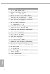
... Power Connector (ATX12V2) 3 CPU Fan Connector (CPU_FAN1) 4 CPU/Water Pump Fan Connector (CPU_FAN2/WP) 5 2 x 288-pin DDR4 DIMM Slots (DDR4_A1, DDR4_B1) 6 2 x 288-pin DDR4 DIMM Slots (DDR4_A2, DDR4_B2) 7 ATX Power Connector (ATXPWR1) 8 USB 3.1 Gen1 Header (USB3_9_10) 9 USB 3.1 Gen1 Header (USB3_7_8) 10 AMD LED Fan USB Header (USB_5) 11 AMD Fan LED Header (AMD_FAN_LED1) 12 Chassis/Water Pump Fan Connector (CHA_FAN1/WP) 13 SATA3 Connectors (SATA3_5_6) 14 SATA3 Connectors (SATA3_3_4) 15 SATA3 Connectors (SATA3_1_2) 16 System Panel Header (PANEL1) 17 RGB LED Header (RGB_LED1) 18 Clear CMOS Jumper...
... Power Connector (ATX12V2) 3 CPU Fan Connector (CPU_FAN1) 4 CPU/Water Pump Fan Connector (CPU_FAN2/WP) 5 2 x 288-pin DDR4 DIMM Slots (DDR4_A1, DDR4_B1) 6 2 x 288-pin DDR4 DIMM Slots (DDR4_A2, DDR4_B2) 7 ATX Power Connector (ATXPWR1) 8 USB 3.1 Gen1 Header (USB3_9_10) 9 USB 3.1 Gen1 Header (USB3_7_8) 10 AMD LED Fan USB Header (USB_5) 11 AMD Fan LED Header (AMD_FAN_LED1) 12 Chassis/Water Pump Fan Connector (CHA_FAN1/WP) 13 SATA3 Connectors (SATA3_5_6) 14 SATA3 Connectors (SATA3_3_4) 15 SATA3 Connectors (SATA3_1_2) 16 System Panel Header (PANEL1) 17 RGB LED Header (RGB_LED1) 18 Clear CMOS Jumper...
User Manual
Page 36
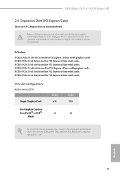
... used for PCI Express x1 lane width cards. Please read the documentation of the expansion card and make sure that the power supply is switched off or the power cord is used for PCI Express x1 lane width cards. PCIE6 (PCIe 2.0 x1 slot) is unplugged. PCIe Slot Configurations Ryzen series CPUs: Single Graphics Card PCIE1 x16 PCIE4 N/A Two Graphics Cards in CrossFireXTM or SLITM x8 x8 Mode For a better thermal environment, please connect a chassis fan to the motherboard's chassis fan connector...
... used for PCI Express x1 lane width cards. Please read the documentation of the expansion card and make sure that the power supply is switched off or the power cord is used for PCI Express x1 lane width cards. PCIE6 (PCIe 2.0 x1 slot) is unplugged. PCIe Slot Configurations Ryzen series CPUs: Single Graphics Card PCIE1 x16 PCIE4 N/A Two Graphics Cards in CrossFireXTM or SLITM x8 x8 Mode For a better thermal environment, please connect a chassis fan to the motherboard's chassis fan connector...
User Manual
Page 39
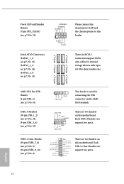
... headers on this motherboard. Please connect the chassis power LED and the chassis speaker to 6.0 Gb/s data transfer rate. These six SATA3 connectors support SATA data cables for connecting the USB connector on the AMD SR3 Heatsink. SATA3_1 SATA3_3 SATA3_5 SATA3_2 SATA3_4 SATA3_6 AMD LED Fan USB Header (4-pin USB_5) (see p.7, No. 10) USB 2.0 Headers ((9-pin USB_1_2) (see p.7, No. 22) (9-pin USB_3_4) (see p.7, No. 13) SPEAKER DUMMY DUMMY +5V 1 PLED+ PLED+ PLED- Power LED and Speaker Header (7-pin SPK_PLED1) (see p.7, No. 24) Serial ATA3 Connectors...
... headers on this motherboard. Please connect the chassis power LED and the chassis speaker to 6.0 Gb/s data transfer rate. These six SATA3 connectors support SATA data cables for connecting the USB connector on the AMD SR3 Heatsink. SATA3_1 SATA3_3 SATA3_5 SATA3_2 SATA3_4 SATA3_6 AMD LED Fan USB Header (4-pin USB_5) (see p.7, No. 10) USB 2.0 Headers ((9-pin USB_1_2) (see p.7, No. 22) (9-pin USB_3_4) (see p.7, No. 13) SPEAKER DUMMY DUMMY +5V 1 PLED+ PLED+ PLED- Power LED and Speaker Header (7-pin SPK_PLED1) (see p.7, No. 24) Serial ATA3 Connectors...
User Manual
Page 47
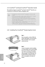
... AMD graphics card manuals for detailed installation guide. 2.8.1 Installing Two CrossFireXTM-Ready Graphics Cards Step 1 Insert one graphics card into PCIE1 slot and the other graphics card to your graphics card vendor for details. 4. CrossFire Bridge Step 2 Connect two graphics cards by installing a CrossFire Bridge on the CrossFire Bridge Interconnects on the slots. Please refer to PCIE4 slot. Make sure that your power supply unit (PSU) can provide at least the minimum power your graphics card driver supports AMD CrossFireXTM technology...
... AMD graphics card manuals for detailed installation guide. 2.8.1 Installing Two CrossFireXTM-Ready Graphics Cards Step 1 Insert one graphics card into PCIE1 slot and the other graphics card to your graphics card vendor for details. 4. CrossFire Bridge Step 2 Connect two graphics cards by installing a CrossFire Bridge on the CrossFire Bridge Interconnects on the slots. Please refer to PCIE4 slot. Make sure that your power supply unit (PSU) can provide at least the minimum power your graphics card driver supports AMD CrossFireXTM technology...
User Manual
Page 49
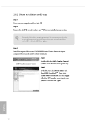
... AMD Catalyst Control Center icon in your graphics card and click Apply. Then select Enable AMD CrossFireX and click Apply. 2.8.2 Driver Installation and Setup Step 1 Power on your computer. The Catalyst Uninstaller is an optional download. Select the GPU number according to your system. Please check AMD's website for AMD driver updates. Step 2 Remove the AMD drivers if you have any previously installed Catalyst drivers prior to uninstall any VGA drivers installed in the Windows...
... AMD Catalyst Control Center icon in your graphics card and click Apply. Then select Enable AMD CrossFireX and click Apply. 2.8.2 Driver Installation and Setup Step 1 Power on your computer. The Catalyst Uninstaller is an optional download. Select the GPU number according to your system. Please check AMD's website for AMD driver updates. Step 2 Remove the AMD drivers if you have any previously installed Catalyst drivers prior to uninstall any VGA drivers installed in the Windows...
User Manual
Page 56
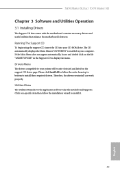
... the Main Menu does not appear automatically, locate and double click on the file "ASRSETUP.EXE" in your system will be auto-detected and listed on a specific item then follow the order from top to bottom to display the menu. Click on the support CD driver page. Utilities Menu The Utilities Menu shows the application software that enhance the motherboard's features. X470 Master SLI/ac / X470 Master SLI Chapter 3 Software and Utilities Operation 3.1 Installing Drivers The Support CD...
... the Main Menu does not appear automatically, locate and double click on the file "ASRSETUP.EXE" in your system will be auto-detected and listed on a specific item then follow the order from top to bottom to display the menu. Click on the support CD driver page. Utilities Menu The Utilities Menu shows the application software that enhance the motherboard's features. X470 Master SLI/ac / X470 Master SLI Chapter 3 Software and Utilities Operation 3.1 Installing Drivers The Support CD...
User Manual
Page 76
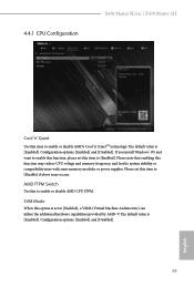
... reduce CPU voltage and memory frequency, and lead to system stability or compatibility issue with some memory modules or power supplies. Please note that enabling this item to [Enabled]. Configuration options: [Enabled] and [Disabled]. 69 English 4.4.1 CPU Configuration X470 Master SLI/ac / X470 Master SLI Cool 'n' Quiet Use this item to [Disable] if above issue occurs. Please set to enable or disable AMD CPU fTPM. The default value is set this item to enable or disable AMD's Cool 'n' QuietTM technology. AMD fTPM Switch Use this option is [Enabled]. SVM Mode When...
... reduce CPU voltage and memory frequency, and lead to system stability or compatibility issue with some memory modules or power supplies. Please note that enabling this item to [Enabled]. Configuration options: [Enabled] and [Disabled]. 69 English 4.4.1 CPU Configuration X470 Master SLI/ac / X470 Master SLI Cool 'n' Quiet Use this item to [Disable] if above issue occurs. Please set to enable or disable AMD CPU fTPM. The default value is set this item to enable or disable AMD's Cool 'n' QuietTM technology. AMD fTPM Switch Use this option is [Enabled]. SVM Mode When...
User Manual
Page 80
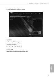
Serial Port Address Select the address of the Serial port. PS2 Y-Cable Enable the PS2 Y-Cable or set this option to Auto. 73 English X470 Master SLI/ac / X470 Master SLI 4.4.5 Super IO Configuration Serial Port Enable or disable the Serial port.
Serial Port Address Select the address of the Serial port. PS2 Y-Cable Enable the PS2 Y-Cable or set this option to Auto. 73 English X470 Master SLI/ac / X470 Master SLI 4.4.5 Super IO Configuration Serial Port Enable or disable the Serial port.
User Manual
Page 84
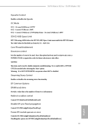
... NOT SUPPORTED on 1.400V SEV-ES ASID Space Limit SEV VMs using ASIDs below the SEV-ES ASID Space Limit must enable the SEV-ES feature. DF Common Options DRAM scrub time Provide a value that is disabled. X470 Master SLI/ac / X470 Master SLI Opcache Control Enables or disables the Opcache. The valid values for future selections to remove any cores, a POWER CYCLE is needed after selecting the 'Auto' option...
... NOT SUPPORTED on 1.400V SEV-ES ASID Space Limit SEV VMs using ASIDs below the SEV-ES ASID Space Limit must enable the SEV-ES feature. DF Common Options DRAM scrub time Provide a value that is disabled. X470 Master SLI/ac / X470 Master SLI Opcache Control Enables or disables the Opcache. The valid values for future selections to remove any cores, a POWER CYCLE is needed after selecting the 'Auto' option...

User Manual
Page 92
After copying the drivers please change the SATA mode to your liking. Easy RAID Installer Easy RAID Installer helps you to copy the RAID driver from the support CD to RAID, then you to adjust the RGB LED color to your USB storage device. 4.5 Tools X470 Master SLI/ac / X470 Master SLI RGB LED ASRock RGB LED allows you can start installing the operating system in RAID mode. 85 English
After copying the drivers please change the SATA mode to your liking. Easy RAID Installer Easy RAID Installer helps you to copy the RAID driver from the support CD to RAID, then you to adjust the RGB LED color to your USB storage device. 4.5 Tools X470 Master SLI/ac / X470 Master SLI RGB LED ASRock RGB LED allows you can start installing the operating system in RAID mode. 85 English
User Manual
Page 93
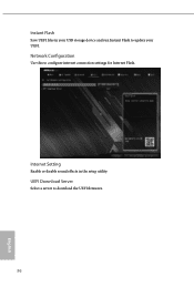
Instant Flash Save UEFI files in the setup utility. Internet Setting Enable or disable sound effects in your USB storage device and run Instant Flash to update your UEFI. UEFI Download Server Select a server to configure internet connection settings for Internet Flash. Network Configuration Use this to download the UEFI firmware. 86 English
Instant Flash Save UEFI files in the setup utility. Internet Setting Enable or disable sound effects in your USB storage device and run Instant Flash to update your UEFI. UEFI Download Server Select a server to configure internet connection settings for Internet Flash. Network Configuration Use this to download the UEFI firmware. 86 English
Quick Installation Guide
Page 6
... Power Connector (ATX12V2) 3 CPU Fan Connector (CPU_FAN1) 4 CPU/Water Pump Fan Connector (CPU_FAN2/WP) 5 2 x 288-pin DDR4 DIMM Slots (DDR4_A1, DDR4_B1) 6 2 x 288-pin DDR4 DIMM Slots (DDR4_A2, DDR4_B2) 7 ATX Power Connector (ATXPWR1) 8 USB 3.1 Gen1 Header (USB3_9_10) 9 USB 3.1 Gen1 Header (USB3_7_8) 10 AMD LED Fan USB Header (USB_5) 11 AMD Fan LED Header (AMD_FAN_LED1) 12 Chassis/Water Pump Fan Connector (CHA_FAN1/WP) 13 SATA3 Connectors (SATA3_5_6) 14 SATA3 Connectors (SATA3_3_4) 15 SATA3 Connectors (SATA3_1_2) 16 System Panel Header (PANEL1) 17 RGB LED Header (RGB_LED1) 18 Clear CMOS Jumper...
... Power Connector (ATX12V2) 3 CPU Fan Connector (CPU_FAN1) 4 CPU/Water Pump Fan Connector (CPU_FAN2/WP) 5 2 x 288-pin DDR4 DIMM Slots (DDR4_A1, DDR4_B1) 6 2 x 288-pin DDR4 DIMM Slots (DDR4_A2, DDR4_B2) 7 ATX Power Connector (ATXPWR1) 8 USB 3.1 Gen1 Header (USB3_9_10) 9 USB 3.1 Gen1 Header (USB3_7_8) 10 AMD LED Fan USB Header (USB_5) 11 AMD Fan LED Header (AMD_FAN_LED1) 12 Chassis/Water Pump Fan Connector (CHA_FAN1/WP) 13 SATA3 Connectors (SATA3_5_6) 14 SATA3 Connectors (SATA3_3_4) 15 SATA3 Connectors (SATA3_1_2) 16 System Panel Header (PANEL1) 17 RGB LED Header (RGB_LED1) 18 Clear CMOS Jumper...
Quick Installation Guide
Page 12
... Panel Shield • 2 x Serial ATA (SATA) Data Cables (Optional) • 1 x ASRock SLI_HB_Bridge_2S Card (Optional) • 2 x Screws for M.2 Sockets (Optional) • 2 x ASRock WiFi 2.4/5 GHz Antennas (Optional) (for purchasing ASRock X470 Master SLI/ac / X470 Master SLI motherboard, a reliable motherboard produced under ASRock's consistently stringent quality control. Because the motherboard specifications and the BIOS software might be updated, the content of this manual will be subject to change without further notice. You may find the latest VGA cards and CPU support list on...
... Panel Shield • 2 x Serial ATA (SATA) Data Cables (Optional) • 1 x ASRock SLI_HB_Bridge_2S Card (Optional) • 2 x Screws for M.2 Sockets (Optional) • 2 x ASRock WiFi 2.4/5 GHz Antennas (Optional) (for purchasing ASRock X470 Master SLI/ac / X470 Master SLI motherboard, a reliable motherboard produced under ASRock's consistently stringent quality control. Because the motherboard specifications and the BIOS software might be updated, the content of this manual will be subject to change without further notice. You may find the latest VGA cards and CPU support list on...
Quick Installation Guide
Page 15
...X470 Master SLI/ac only) • 1 x PS/2 Mouse/Keyboard Port • 1 x HDMI Port • 1 x Optical SPDIF Out Port • 1 x USB 3.1 Gen2 Type-A Port (10 Gb/s) (Supports ESD Protection) • 1 x USB 3.1 Gen2 Type-C Port (10 Gb/s) (Supports ESD Protection) • 6 x USB 3.1 Gen1 Ports (Supports ESD Protection) • 1 x RJ-45 LAN Port with LED (ACT/LINK LED and SPEED LED) • HD Audio Jacks: Rear Speaker / Central / Bass / Line in / Front Speaker / Microphone (Gold Audio Jacks) Storage • 6 x SATA3 6.0 Gb/s Connectors, support RAID (RAID 0, RAID 1 and RAID 10), NCQ, AHCI...
...X470 Master SLI/ac only) • 1 x PS/2 Mouse/Keyboard Port • 1 x HDMI Port • 1 x Optical SPDIF Out Port • 1 x USB 3.1 Gen2 Type-A Port (10 Gb/s) (Supports ESD Protection) • 1 x USB 3.1 Gen2 Type-C Port (10 Gb/s) (Supports ESD Protection) • 6 x USB 3.1 Gen1 Ports (Supports ESD Protection) • 1 x RJ-45 LAN Port with LED (ACT/LINK LED and SPEED LED) • HD Audio Jacks: Rear Speaker / Central / Bass / Line in / Front Speaker / Microphone (Gold Audio Jacks) Storage • 6 x SATA3 6.0 Gb/s Connectors, support RAID (RAID 0, RAID 1 and RAID 10), NCQ, AHCI...


