
RAID Installation Guide
Page 2
... data loss. Hot-Plug any fault tolerance. RAID 0 (Data Striping) RAID 0 is called data striping that copies and maintains an identical image of the "User Manual" in our support CD, then you to configure RAID functions by following the detailed instruction of data from one drive fails. 2 WARNING!! For optimal performance...
... data loss. Hot-Plug any fault tolerance. RAID 0 (Data Striping) RAID 0 is called data striping that copies and maintains an identical image of the "User Manual" in our support CD, then you to configure RAID functions by following the detailed instruction of data from one drive fails. 2 WARNING!! For optimal performance...

User Manual
Page 6
... guide of the software and utilities. In this manual occur, the updated version will be updated, the content of the motherboard and step-by-step installation guides. ASRock website http://www.asrock.com. 1.1 Package Contents • ASRock X370M Pro4 Motherboard (Micro ATX Form Factor) • ASRock X370M Pro4 Quick Installation Guide • ASRock X370M Pro4 Support CD • 1 x I/O Panel Shield • 2 x Serial...
... guide of the software and utilities. In this manual occur, the updated version will be updated, the content of the motherboard and step-by-step installation guides. ASRock website http://www.asrock.com. 1.1 Package Contents • ASRock X370M Pro4 Motherboard (Micro ATX Form Factor) • ASRock X370M Pro4 Quick Installation Guide • ASRock X370M Pro4 Support CD • 1 x I/O Panel Shield • 2 x Serial...
User Manual
Page 34
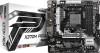
... (LIN) to install your system. 2. D. Connect Mic_IN (MIC) to the "FrontMic" Tab in our manual and chassis manual to OUT2_L. MIC_RET and OUT_RET are for the AC'97 audio panel. B. To activate the front mic, go to MIC2_L. X370M Pro4 USB 3.1 Gen1 Header (19-pin USB3_3_4) (see p.6, No. 22) GND PRESENCE# MIC_RET OUT_RET 1 OUT2_L...
... (LIN) to install your system. 2. D. Connect Mic_IN (MIC) to the "FrontMic" Tab in our manual and chassis manual to OUT2_L. MIC_RET and OUT_RET are for the AC'97 audio panel. B. To activate the front mic, go to MIC2_L. X370M Pro4 USB 3.1 Gen1 Header (19-pin USB3_3_4) (see p.6, No. 22) GND PRESENCE# MIC_RET OUT_RET 1 OUT2_L...
Quick Installation Guide
Page 7
... using. ASRock website http://www.asrock.com. 1.1 Package Contents • ASRock X370M Pro4 Motherboard (Micro ATX Form Factor) • ASRock X370M Pro4 Quick Installation Guide • ASRock X370M Pro4 Support CD • 1 x I/O Panel Shield • 2 x Serial ATA (SATA) Data Cables (Optional) • 2 x Screws for purchasing ASRock X370M Pro4 motherboard, a reliable motherboard produced under ASRock's consistently stringent quality control. In case any modifications of this manual will...
... using. ASRock website http://www.asrock.com. 1.1 Package Contents • ASRock X370M Pro4 Motherboard (Micro ATX Form Factor) • ASRock X370M Pro4 Quick Installation Guide • ASRock X370M Pro4 Support CD • 1 x I/O Panel Shield • 2 x Serial ATA (SATA) Data Cables (Optional) • 2 x Screws for purchasing ASRock X370M Pro4 motherboard, a reliable motherboard produced under ASRock's consistently stringent quality control. In case any modifications of this manual will...

Quick Installation Guide
Page 31
Connect Ground (GND) to OUT2_L. English 29 X370M Pro4 USB 3.1 Gen1 Header (19-pin USB3_3_4) (see p.1, No. 22) GND PRESENCE# MIC_RET OUT_RET 1 OUT2_L J_SENSE OUT2_R MIC2_R MIC2_L This header is one header on the... follow the instructions in the Realtek Control panel and adjust "Recording Volume". E. To activate the front mic, go to the "FrontMic" Tab in our manual and chassis manual to function correctly. Chassis Fan Connectors (4-pin CHA_FAN1) (see p.1, No. 23) FAN_SPEED_CONTROL CHA_FAN_SPEED FAN_VOLTAGE GND (3-pin CHA_FAN2) (see p.1, No. 16) GND FAN_VOLTAGE FAN_SPEED ...
Connect Ground (GND) to OUT2_L. English 29 X370M Pro4 USB 3.1 Gen1 Header (19-pin USB3_3_4) (see p.1, No. 22) GND PRESENCE# MIC_RET OUT_RET 1 OUT2_L J_SENSE OUT2_R MIC2_R MIC2_L This header is one header on the... follow the instructions in the Realtek Control panel and adjust "Recording Volume". E. To activate the front mic, go to the "FrontMic" Tab in our manual and chassis manual to function correctly. Chassis Fan Connectors (4-pin CHA_FAN1) (see p.1, No. 23) FAN_SPEED_CONTROL CHA_FAN_SPEED FAN_VOLTAGE GND (3-pin CHA_FAN2) (see p.1, No. 16) GND FAN_VOLTAGE FAN_SPEED ...
