User Manual
Page 4
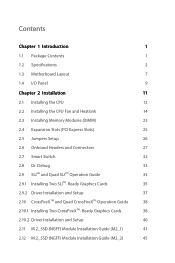
... 1 1.1 Package Contents 1 1.2 Specifications 2 1.3 Motherboard Layout 7 1.4 I/O Panel 9 Chapter 2 Installation 11 2.1 Installing the CPU 12 2.2 Installing the CPU Fan and Heatsink 14 2.3 Installing Memory Modules (DIMM) 23 2.4 Expansion Slots (PCI Express Slots) 25 2.5 Jumpers Setup 26 2.6 Onboard Headers and Connectors 27 2.7 Smart Switch 32 2.8 Dr. Debug 33 2.9 SLITM and Quad SLITM Operation Guide 35...
... 1 1.1 Package Contents 1 1.2 Specifications 2 1.3 Motherboard Layout 7 1.4 I/O Panel 9 Chapter 2 Installation 11 2.1 Installing the CPU 12 2.2 Installing the CPU Fan and Heatsink 14 2.3 Installing Memory Modules (DIMM) 23 2.4 Expansion Slots (PCI Express Slots) 25 2.5 Jumpers Setup 26 2.6 Onboard Headers and Connectors 27 2.7 Smart Switch 32 2.8 Dr. Debug 33 2.9 SLITM and Quad SLITM Operation Guide 35...
User Manual
Page 10
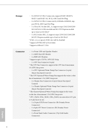
... boot disks * Supports ASRock U.2 Kit Connector • 1 x Power LED and Speaker Header • 1 x AMD Fan LED Header • 2 x RGB LED Headers * Supports up to 12V/3A, 36W LED Strip • 1 x CPU Fan Connector (4-pin) * The CPU Fan Connector supports the CPU fan of maximum 1A (12W) fan power. • 1 x CPU Optional/Water Pump Fan Connector (4-pin) (Smart Fan Speed Control) * The...
... boot disks * Supports ASRock U.2 Kit Connector • 1 x Power LED and Speaker Header • 1 x AMD Fan LED Header • 2 x RGB LED Headers * Supports up to 12V/3A, 36W LED Strip • 1 x CPU Fan Connector (4-pin) * The CPU Fan Connector supports the CPU fan of maximum 1A (12W) fan power. • 1 x CPU Optional/Water Pump Fan Connector (4-pin) (Smart Fan Speed Control) * The...
User Manual
Page 11
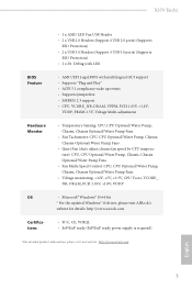
X370 Taichi • 1 x AMD LED Fan USB Header • 2 x USB 2.0 Headers (Support 4 USB 2.0 ports) (Supports ESD Protection) • 2 x USB 3.0 Headers (Support 4 USB 3.0 ports) (Supports ESD Protection) • 1 x Dr. Debug with LED BIOS Feature • AMI UEFI Legal BIOS with... Optional/Water Pump Fans • Voltage monitoring: +12V, +5V, +3.3V, CPU Vcore, VCORE_ NB, DRAM, PCH 1.05V, +1.8V, VDDP OS • Microsoft® Windows® 10 64-bit * For the updated Windows® 10 driver, please visit ASRock's website for details: http://www.asrock.com Certifications •...
X370 Taichi • 1 x AMD LED Fan USB Header • 2 x USB 2.0 Headers (Support 4 USB 2.0 ports) (Supports ESD Protection) • 2 x USB 3.0 Headers (Support 4 USB 3.0 ports) (Supports ESD Protection) • 1 x Dr. Debug with LED BIOS Feature • AMI UEFI Legal BIOS with... Optional/Water Pump Fans • Voltage monitoring: +12V, +5V, +3.3V, CPU Vcore, VCORE_ NB, DRAM, PCH 1.05V, +1.8V, VDDP OS • Microsoft® Windows® 10 64-bit * For the updated Windows® 10 driver, please visit ASRock's website for details: http://www.asrock.com Certifications •...
User Manual
Page 14
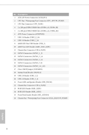
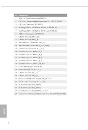
...-pin DDR4 DIMM Slots (DDR4_A1, DDR4_B1) 5 2 x 288-pin DDR4 DIMM Slots (DDR4_A2, DDR4_B2) 6 ATX Power Connector (ATXPWR1) 7 USB 3.0 Header (USB3_9_10) 8 USB 3.0 Header (USB3_7_8) 9 AMD LED Fan USB Header (USB_5) 10 AMD Fan LED Header (AMD_FAN_LED1) 11 Chassis Fan Connector (CHA_FAN1) 12 SATA3 Connectors (SATA3_1_2) 13 SATA3 Connectors (SATA3_3_4) 14 SATA3 Connectors (SATA3_5_6) 15 SATA3 Connectors (SATA3_7_8) 16...
...-pin DDR4 DIMM Slots (DDR4_A1, DDR4_B1) 5 2 x 288-pin DDR4 DIMM Slots (DDR4_A2, DDR4_B2) 6 ATX Power Connector (ATXPWR1) 7 USB 3.0 Header (USB3_9_10) 8 USB 3.0 Header (USB3_7_8) 9 AMD LED Fan USB Header (USB_5) 10 AMD Fan LED Header (AMD_FAN_LED1) 11 Chassis Fan Connector (CHA_FAN1) 12 SATA3 Connectors (SATA3_1_2) 13 SATA3 Connectors (SATA3_3_4) 14 SATA3 Connectors (SATA3_5_6) 15 SATA3 Connectors (SATA3_7_8) 16...

User Manual
Page 24
Please refer to page 31 for reference only. 4 CPU_FAN1 5 RGB LED Cable 4-pin FAN cable CPU_FAN1 +12V AMD_FAN_LED1 *The diagram shown here are for the orientation of AMD Fan LED Header (AMD_FAN_LED1). 18 English
Please refer to page 31 for reference only. 4 CPU_FAN1 5 RGB LED Cable 4-pin FAN cable CPU_FAN1 +12V AMD_FAN_LED1 *The diagram shown here are for the orientation of AMD Fan LED Header (AMD_FAN_LED1). 18 English

User Manual
Page 28
If you select USB connector, please install AMD utility "SR3 Settings Software". *The diagram shown here are for the orientation of AMD LED Fan USB Header (USB_5). 22 English Please refer to page 31 for the orientation of AMD Fan LED Header (AMD_FAN_LED1) and page 28 for reference only. If you select AMD_FAN_LED1, please install ASRock utility "ASRock RGB LED". 6 CPU_FAN1 +12V AMD_FAN_LED1 or 7 CPU_FAN1 AMD_FAN_LED1 USB_5 Please note that only one cable should be used at a time in this step.
If you select USB connector, please install AMD utility "SR3 Settings Software". *The diagram shown here are for the orientation of AMD LED Fan USB Header (USB_5). 22 English Please refer to page 31 for the orientation of AMD Fan LED Header (AMD_FAN_LED1) and page 28 for reference only. If you select AMD_FAN_LED1, please install ASRock utility "ASRock RGB LED". 6 CPU_FAN1 +12V AMD_FAN_LED1 or 7 CPU_FAN1 AMD_FAN_LED1 USB_5 Please note that only one cable should be used at a time in this step.
User Manual
Page 34
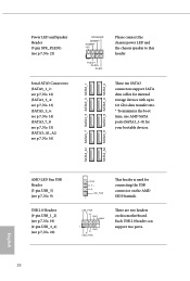
... transfer rate. * To minimize the boot time, use AMD SATA ports (SATA3_1~8) for your bootable devices. Each USB 2.0 header can support two ports. 28 English AMD LED Fan USB Header (5-pin USB_5) (see p.7, No. 9) USB 2.0 Headers (9-pin USB_1_2) (see p.7, No. 19) (9-pin USB_3_4) (see p.7, No. 16) SPEAKER DUMMY DUMMY +5V 1 PLED+ PLED+ PLED- SATA3_A1...
... transfer rate. * To minimize the boot time, use AMD SATA ports (SATA3_1~8) for your bootable devices. Each USB 2.0 header can support two ports. 28 English AMD LED Fan USB Header (5-pin USB_5) (see p.7, No. 9) USB 2.0 Headers (9-pin USB_1_2) (see p.7, No. 19) (9-pin USB_3_4) (see p.7, No. 16) SPEAKER DUMMY DUMMY +5V 1 PLED+ PLED+ PLED- SATA3_A1...
User Manual
Page 35
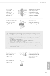
... (see p.7, No. 22) FAN_SPEED_CONTROL CHA_FAN_SPEED FAN_VOLTAGE GND Please connect fan cables to the fan connectors and match the black wire to the ground pin. Connect Mic_IN (MIC) to OUT2_L. D. E. Each USB 3.0 header can support two ports. Connect Audio_R (RIN) to OUT2_R and... on this motherboard. Chassis Fan Connectors (4-pin CHA_FAN1) (see p.7, No. 11) (4-pin CHA_FAN2) (see p.7, No. 25) GND PRESENCE# MIC_RET OUT_RET 1 OUT2_L J_SENSE OUT2_R MIC2_R MIC2_L This header is for connecting audio devices to the front audio panel. 1. X370 Taichi USB 3.0 Header (19-pin USB3_7_8) (...
... (see p.7, No. 22) FAN_SPEED_CONTROL CHA_FAN_SPEED FAN_VOLTAGE GND Please connect fan cables to the fan connectors and match the black wire to the ground pin. Connect Mic_IN (MIC) to OUT2_L. D. E. Each USB 3.0 header can support two ports. Connect Audio_R (RIN) to OUT2_R and... on this motherboard. Chassis Fan Connectors (4-pin CHA_FAN1) (see p.7, No. 11) (4-pin CHA_FAN2) (see p.7, No. 25) GND PRESENCE# MIC_RET OUT_RET 1 OUT2_L J_SENSE OUT2_R MIC2_R MIC2_L This header is for connecting audio devices to the front audio panel. 1. X370 Taichi USB 3.0 Header (19-pin USB3_7_8) (...

User Manual
Page 37
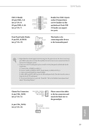
...page 59 for further instructions on these two headers. Caution: Never install the FAN LED cable in the wrong orientation; The cable connection allows users to connect RGB LED extension cable that comes with AMD heatsink. English 31 X370 Taichi RGB LED Headers (4-pin RGB_LED1) (see p.7, No. 24...) (4-pin RGB_LED2) (see p.7, No. 23) 1 12V G R B AMD Fan LED Header (4-pin AMD_FAN_ LED1) (see p.7, No. 10) B R G 12V 1 These two RGB headers are used to choose from various LED lighting...
...page 59 for further instructions on these two headers. Caution: Never install the FAN LED cable in the wrong orientation; The cable connection allows users to connect RGB LED extension cable that comes with AMD heatsink. English 31 X370 Taichi RGB LED Headers (4-pin RGB_LED1) (see p.7, No. 24...) (4-pin RGB_LED2) (see p.7, No. 23) 1 12V G R B AMD Fan LED Header (4-pin AMD_FAN_ LED1) (see p.7, No. 10) B R G 12V 1 These two RGB headers are used to choose from various LED lighting...
Quick Installation Guide
Page 4
...-pin DDR4 DIMM Slots (DDR4_A1, DDR4_B1) 5 2 x 288-pin DDR4 DIMM Slots (DDR4_A2, DDR4_B2) 6 ATX Power Connector (ATXPWR1) 7 USB 3.0 Header (USB3_9_10) 8 USB 3.0 Header (USB3_7_8) 9 AMD LED Fan USB Header (USB_5) 10 AMD Fan LED Header (AMD_FAN_LED1) 11 Chassis Fan Connector (CHA_FAN1) 12 SATA3 Connectors (SATA3_1_2) 13 SATA3 Connectors (SATA3_3_4) 14 SATA3 Connectors (SATA3_5_6) 15 SATA3 Connectors (SATA3_7_8) 16...
...-pin DDR4 DIMM Slots (DDR4_A1, DDR4_B1) 5 2 x 288-pin DDR4 DIMM Slots (DDR4_A2, DDR4_B2) 6 ATX Power Connector (ATXPWR1) 7 USB 3.0 Header (USB3_9_10) 8 USB 3.0 Header (USB3_7_8) 9 AMD LED Fan USB Header (USB_5) 10 AMD Fan LED Header (AMD_FAN_LED1) 11 Chassis Fan Connector (CHA_FAN1) 12 SATA3 Connectors (SATA3_1_2) 13 SATA3 Connectors (SATA3_3_4) 14 SATA3 Connectors (SATA3_5_6) 15 SATA3 Connectors (SATA3_7_8) 16...
Quick Installation Guide
Page 10
... boot disks * Supports ASRock U.2 Kit Connector • 1 x Power LED and Speaker Header • 1 x AMD Fan LED Header • 2 x RGB LED Headers * Supports up to 12V/3A, 36W LED Strip • 1 x CPU Fan Connector (4-pin) * The CPU Fan Connector supports the CPU fan of maximum 1A (12W) fan power. • 1 x CPU Optional/Water Pump Fan Connector (4-pin) (Smart Fan Speed Control) * The...
... boot disks * Supports ASRock U.2 Kit Connector • 1 x Power LED and Speaker Header • 1 x AMD Fan LED Header • 2 x RGB LED Headers * Supports up to 12V/3A, 36W LED Strip • 1 x CPU Fan Connector (4-pin) * The CPU Fan Connector supports the CPU fan of maximum 1A (12W) fan power. • 1 x CPU Optional/Water Pump Fan Connector (4-pin) (Smart Fan Speed Control) * The...
Quick Installation Guide
Page 11
X370 Taichi • 1 x AMD LED Fan USB Header • 2 x USB 2.0 Headers (Support 4 USB 2.0 ports) (Supports ESD Protection) • 2 x USB 3.0 Headers (Support 4 USB 3.0 ports) (Supports ESD Protection) • 1 x Dr. Debug with LED BIOS Feature • AMI UEFI Legal BIOS with... Optional/Water Pump Fans • Voltage monitoring: +12V, +5V, +3.3V, CPU Vcore, VCORE_ NB, DRAM, PCH 1.05V, +1.8V, VDDP OS • Microsoft® Windows® 10 64-bit * For the updated Windows® 10 driver, please visit ASRock's website for details: http://www.asrock.com Certifications •...
X370 Taichi • 1 x AMD LED Fan USB Header • 2 x USB 2.0 Headers (Support 4 USB 2.0 ports) (Supports ESD Protection) • 2 x USB 3.0 Headers (Support 4 USB 3.0 ports) (Supports ESD Protection) • 1 x Dr. Debug with LED BIOS Feature • AMI UEFI Legal BIOS with... Optional/Water Pump Fans • Voltage monitoring: +12V, +5V, +3.3V, CPU Vcore, VCORE_ NB, DRAM, PCH 1.05V, +1.8V, VDDP OS • Microsoft® Windows® 10 64-bit * For the updated Windows® 10 driver, please visit ASRock's website for details: http://www.asrock.com Certifications •...

Quick Installation Guide
Page 20
4 CPU_FAN1 5 RGB LED Cable 4-pin FAN cable CPU_FAN1 +12V AMD_FAN_LED1 *The diagram shown here are for the orientation of AMD Fan LED Header (AMD_FAN_LED1). 18 English Please refer to page 31 for reference only.
4 CPU_FAN1 5 RGB LED Cable 4-pin FAN cable CPU_FAN1 +12V AMD_FAN_LED1 *The diagram shown here are for the orientation of AMD Fan LED Header (AMD_FAN_LED1). 18 English Please refer to page 31 for reference only.

Quick Installation Guide
Page 24
If you select AMD_FAN_LED1, please install ASRock utility "ASRock RGB LED". If you select USB connector, please install AMD utility "SR3 Settings Software". *The diagram shown here are for the orientation of AMD LED Fan USB Header (USB_5). 22 English Please refer to page 31 for the orientation of AMD Fan LED Header (AMD_FAN_LED1) and page 28 for reference only. 6 CPU_FAN1 +12V AMD_FAN_LED1 or 7 CPU_FAN1 AMD_FAN_LED1 USB_5 Please note that only one cable should be used at a time in this step.
If you select AMD_FAN_LED1, please install ASRock utility "ASRock RGB LED". If you select USB connector, please install AMD utility "SR3 Settings Software". *The diagram shown here are for the orientation of AMD LED Fan USB Header (USB_5). 22 English Please refer to page 31 for the orientation of AMD Fan LED Header (AMD_FAN_LED1) and page 28 for reference only. 6 CPU_FAN1 +12V AMD_FAN_LED1 or 7 CPU_FAN1 AMD_FAN_LED1 USB_5 Please note that only one cable should be used at a time in this step.
Quick Installation Guide
Page 30
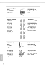
These ten SATA3 connectors support SATA data cables for internal storage devices with up to this motherboard. AMD LED Fan USB Header (5-pin USB_5) (see p.7, No. 9) USB 2.0 Headers (9-pin USB_1_2) (see p.7, No. 19) (9-pin USB_3_4) (see p.7, No. 16) SPEAKER DUMMY DUMMY +5V 1 PLED+... PLED+ PLED- SATA3_A1 SATA3_7 SATA3_5 SATA3_3 SATA3_1 SATA3_A2 SATA3_8 SATA3_6 SATA3_4 SATA3_2 Power LED and Speaker Header (7-pin SPK_PLED1) (see p.7, No. 21) Serial ATA3 Connectors (SATA3_1_2: see p.7, No. 12) (SATA3_3_4: see p.7, No. 13) (SATA3_5_6: see p.7, No...
These ten SATA3 connectors support SATA data cables for internal storage devices with up to this motherboard. AMD LED Fan USB Header (5-pin USB_5) (see p.7, No. 9) USB 2.0 Headers (9-pin USB_1_2) (see p.7, No. 19) (9-pin USB_3_4) (see p.7, No. 16) SPEAKER DUMMY DUMMY +5V 1 PLED+... PLED+ PLED- SATA3_A1 SATA3_7 SATA3_5 SATA3_3 SATA3_1 SATA3_A2 SATA3_8 SATA3_6 SATA3_4 SATA3_2 Power LED and Speaker Header (7-pin SPK_PLED1) (see p.7, No. 21) Serial ATA3 Connectors (SATA3_1_2: see p.7, No. 12) (SATA3_3_4: see p.7, No. 13) (SATA3_5_6: see p.7, No...
Quick Installation Guide
Page 31
... audio panel, please install it to OUT2_L. C. Each USB 3.0 header can support two ports. Connect Audio_R (RIN) to OUT2_R and Audio_L (LIN) to the front panel audio header by the steps below: A. Chassis Fan Connectors (4-pin CHA_FAN1) (see p.7, No. 11) (4-pin CHA_FAN2)... (see p.7, No. 25) GND PRESENCE# MIC_RET OUT_RET 1 OUT2_L J_SENSE OUT2_R MIC2_R MIC2_L This header is for connecting audio devices to function correctly. X370 Taichi USB 3.0 Header (19-pin USB3_7_8...
... audio panel, please install it to OUT2_L. C. Each USB 3.0 header can support two ports. Connect Audio_R (RIN) to OUT2_R and Audio_L (LIN) to the front panel audio header by the steps below: A. Chassis Fan Connectors (4-pin CHA_FAN1) (see p.7, No. 11) (4-pin CHA_FAN2)... (see p.7, No. 25) GND PRESENCE# MIC_RET OUT_RET 1 OUT2_L J_SENSE OUT2_R MIC2_R MIC2_L This header is for connecting audio devices to function correctly. X370 Taichi USB 3.0 Header (19-pin USB3_7_8...

Quick Installation Guide
Page 33
.... otherwise, the cable may be damaged. otherwise, the cable may be damaged. X370 Taichi RGB LED Headers (4-pin RGB_LED1) (see p.7, No. 24) (4-pin RGB_LED2) (see p.7, No. 23) 1 12V G R B AMD Fan LED Header (4-pin AMD_FAN_ LED1) (see p.7, No. 10) B R G 12V 1 These two RGB headers are used to connect RGB LED extension cable that comes with AMD heatsink.
.... otherwise, the cable may be damaged. otherwise, the cable may be damaged. X370 Taichi RGB LED Headers (4-pin RGB_LED1) (see p.7, No. 24) (4-pin RGB_LED2) (see p.7, No. 23) 1 12V G R B AMD Fan LED Header (4-pin AMD_FAN_ LED1) (see p.7, No. 10) B R G 12V 1 These two RGB headers are used to connect RGB LED extension cable that comes with AMD heatsink.


