User Manual
Page 4
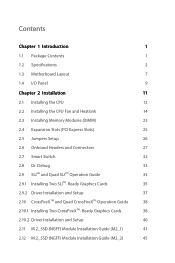
Contents Chapter 1 Introduction 1 1.1 Package Contents 1 1.2 Specifications 2 1.3 Motherboard Layout 7 1.4 I/O Panel 9 Chapter 2 Installation 11 2.1 Installing the CPU 12 2.2 Installing the CPU Fan and Heatsink 14 2.3 Installing Memory Modules (DIMM) 23 2.4 Expansion Slots (PCI Express Slots) 25 2.5 Jumpers Setup 26 2.6 Onboard Headers and Connectors 27 2.7 Smart Switch 32 2.8 Dr. Debug 33 2.9 SLITM and Quad SLITM Operation Guide 35 2.9.1 Installing Two SLITM-Ready Graphics Cards 35 2.9.2 Driver Installation and Setup 37 2.10 CrossFireXTM and Quad ...
Contents Chapter 1 Introduction 1 1.1 Package Contents 1 1.2 Specifications 2 1.3 Motherboard Layout 7 1.4 I/O Panel 9 Chapter 2 Installation 11 2.1 Installing the CPU 12 2.2 Installing the CPU Fan and Heatsink 14 2.3 Installing Memory Modules (DIMM) 23 2.4 Expansion Slots (PCI Express Slots) 25 2.5 Jumpers Setup 26 2.6 Onboard Headers and Connectors 27 2.7 Smart Switch 32 2.8 Dr. Debug 33 2.9 SLITM and Quad SLITM Operation Guide 35 2.9.1 Installing Two SLITM-Ready Graphics Cards 35 2.9.2 Driver Installation and Setup 37 2.10 CrossFireXTM and Quad ...
User Manual
Page 7
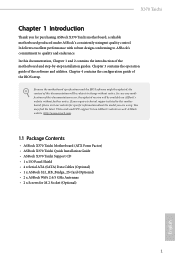
... be subject to change without further notice. Chapter 4 contains the configuration guide of this motherboard, please visit our website for specific information about the model you for M.2 Socket (Optional) 1 English ASRock website http://www.asrock.com. 1.1 Package Contents • ASRock X370 Taichi Motherboard (ATX Form Factor) • ASRock X370 Taichi Quick Installation Guide • ASRock X370 Taichi Support CD • 1 x I/O Panel Shield • 4 x Serial ATA (SATA) Data Cables (Optional) • 1 x ASRock SLI_HB_Bridge_2S Card (Optional) • 2 x ASRock WiFi 2.4/5 GHz...
... be subject to change without further notice. Chapter 4 contains the configuration guide of this motherboard, please visit our website for specific information about the model you for M.2 Socket (Optional) 1 English ASRock website http://www.asrock.com. 1.1 Package Contents • ASRock X370 Taichi Motherboard (ATX Form Factor) • ASRock X370 Taichi Quick Installation Guide • ASRock X370 Taichi Support CD • 1 x I/O Panel Shield • 4 x Serial ATA (SATA) Data Cables (Optional) • 1 x ASRock SLI_HB_Bridge_2S Card (Optional) • 2 x ASRock WiFi 2.4/5 GHz...
User Manual
Page 10
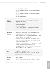
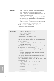
... Socket (M2_2), supports type 2230/2242/2260/2280 M.2 PCI Express module up to Gen2 x4 (20 Gb/s)* * If M2_2 is occupied, PCIE5 slot will be disabled * Supports NVMe SSD as boot disks * Supports ASRock U.2 Kit Connector • 1 x Power LED and Speaker Header • 1 x AMD Fan LED Header • 2 x RGB LED Headers * Supports up to 12V/3A, 36W LED Strip • 1 x CPU Fan Connector (4-pin) * The CPU Fan Connector supports the CPU fan of maximum 1A (12W) fan power. • 1 x CPU Optional/Water Pump Fan Connector (4-pin) (Smart Fan Speed Control) * The CPU Optional/Water Pump Fan supports...
... Socket (M2_2), supports type 2230/2242/2260/2280 M.2 PCI Express module up to Gen2 x4 (20 Gb/s)* * If M2_2 is occupied, PCIE5 slot will be disabled * Supports NVMe SSD as boot disks * Supports ASRock U.2 Kit Connector • 1 x Power LED and Speaker Header • 1 x AMD Fan LED Header • 2 x RGB LED Headers * Supports up to 12V/3A, 36W LED Strip • 1 x CPU Fan Connector (4-pin) * The CPU Fan Connector supports the CPU fan of maximum 1A (12W) fan power. • 1 x CPU Optional/Water Pump Fan Connector (4-pin) (Smart Fan Speed Control) * The CPU Optional/Water Pump Fan supports...
User Manual
Page 11
X370 Taichi • 1 x AMD LED Fan USB Header • 2 x USB 2.0 Headers (Support 4 USB 2.0 ports) (Supports ESD Protection) • 2 x USB 3.0 Headers (Support 4 USB 3.0 ports) (Supports ESD Protection) • 1 x Dr. Debug with LED BIOS Feature • AMI UEFI Legal BIOS with multilingual GUI support • Supports "Plug and Play" • ACPI 5.1 compliance wake up events • Supports jumperfree • SMBIOS 2.3 support • CPU, VCORE_NB, DRAM, VPPM, PCH 1.05V, +1.8V, VDDP, PROM 2.5V, Voltage Multi-adjustment Hardware Monitor • Temperature Sensing: CPU, CPU ...
X370 Taichi • 1 x AMD LED Fan USB Header • 2 x USB 2.0 Headers (Support 4 USB 2.0 ports) (Supports ESD Protection) • 2 x USB 3.0 Headers (Support 4 USB 3.0 ports) (Supports ESD Protection) • 1 x Dr. Debug with LED BIOS Feature • AMI UEFI Legal BIOS with multilingual GUI support • Supports "Plug and Play" • ACPI 5.1 compliance wake up events • Supports jumperfree • SMBIOS 2.3 support • CPU, VCORE_NB, DRAM, VPPM, PCH 1.05V, +1.8V, VDDP, PROM 2.5V, Voltage Multi-adjustment Hardware Monitor • Temperature Sensing: CPU, CPU ...
User Manual
Page 14
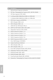
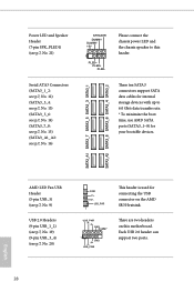
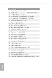
... x 288-pin DDR4 DIMM Slots (DDR4_A2, DDR4_B2) 6 ATX Power Connector (ATXPWR1) 7 USB 3.0 Header (USB3_9_10) 8 USB 3.0 Header (USB3_7_8) 9 AMD LED Fan USB Header (USB_5) 10 AMD Fan LED Header (AMD_FAN_LED1) 11 Chassis Fan Connector (CHA_FAN1) 12 SATA3 Connectors (SATA3_1_2) 13 SATA3 Connectors (SATA3_3_4) 14 SATA3 Connectors (SATA3_5_6) 15 SATA3 Connectors (SATA3_7_8) 16 SATA3 Connectors (SATA3_A1_A2) 17 Clear CMOS Jumper (CLRMOS1) 18 System Panel Header (PANEL1) 19 USB 2.0 Header (USB_1_2) 20 USB 2.0 Header (USB_3_4) 21 Power LED and Speaker Header (SPK_PLED1) 22 Chassis Fan Connector (CHA_FAN2...
... x 288-pin DDR4 DIMM Slots (DDR4_A2, DDR4_B2) 6 ATX Power Connector (ATXPWR1) 7 USB 3.0 Header (USB3_9_10) 8 USB 3.0 Header (USB3_7_8) 9 AMD LED Fan USB Header (USB_5) 10 AMD Fan LED Header (AMD_FAN_LED1) 11 Chassis Fan Connector (CHA_FAN1) 12 SATA3 Connectors (SATA3_1_2) 13 SATA3 Connectors (SATA3_3_4) 14 SATA3 Connectors (SATA3_5_6) 15 SATA3 Connectors (SATA3_7_8) 16 SATA3 Connectors (SATA3_A1_A2) 17 Clear CMOS Jumper (CLRMOS1) 18 System Panel Header (PANEL1) 19 USB 2.0 Header (USB_1_2) 20 USB 2.0 Header (USB_3_4) 21 Power LED and Speaker Header (SPK_PLED1) 22 Chassis Fan Connector (CHA_FAN2...
User Manual
Page 15
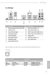
... Speaker (Lime)** 7 Microphone (Pink) 12 USB 3.1 Type-C Port (USB31_TC_1) 13 Antenna Ports 14 USB 3.0 Port (USB3_1_2) 15 Clear CMOS Switch 8 Optical SPDIF Out Port * There are two LEDs on each LAN port. ACT/LINK LED SPEED LED LAN Port Activity / Link LED Status Description Off Blinking On No Link Data Activity Link Speed LED Status Orange Orange Green Description 10Mbps connection 100Mbps connection 1Gbps connection 9 English Please refer to the table below for the LAN port LED indications. 1.4 I/O Panel 1 X370 Taichi 35...
... Speaker (Lime)** 7 Microphone (Pink) 12 USB 3.1 Type-C Port (USB31_TC_1) 13 Antenna Ports 14 USB 3.0 Port (USB3_1_2) 15 Clear CMOS Switch 8 Optical SPDIF Out Port * There are two LEDs on each LAN port. ACT/LINK LED SPEED LED LAN Port Activity / Link LED Status Description Off Blinking On No Link Data Activity Link Speed LED Status Orange Orange Green Description 10Mbps connection 100Mbps connection 1Gbps connection 9 English Please refer to the table below for the LAN port LED indications. 1.4 I/O Panel 1 X370 Taichi 35...
User Manual
Page 31
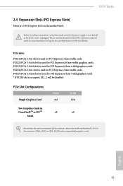
...be disabled PCIe Slot Configurations Single Graphics Card PCIE2 x16 PCIE3 N/A Two Graphics Cards in CrossFireXTM or SLITM x8 x8 Mode For a better thermal environment, please connect a chassis fan to the motherboard's chassis fan connector (CHA_FAN1 or CHA_FAN2) when using multiple graphics cards. PCIe slots: PCIE1 (PCIe 2.0 x1 slot) is used for PCI Express x4 lane width graphics cards. * If PCIE5 slot is used for PCI Express x1 lane width cards. PCIE4 (PCIe 2.0 x1 slot) is used for PCI Express x16 lane width graphics cards. PCIE2 (PCIe 3.0 x16 slot) is used for PCI Express...
...be disabled PCIe Slot Configurations Single Graphics Card PCIE2 x16 PCIE3 N/A Two Graphics Cards in CrossFireXTM or SLITM x8 x8 Mode For a better thermal environment, please connect a chassis fan to the motherboard's chassis fan connector (CHA_FAN1 or CHA_FAN2) when using multiple graphics cards. PCIe slots: PCIE1 (PCIe 2.0 x1 slot) is used for PCI Express x4 lane width graphics cards. * If PCIE5 slot is used for PCI Express x1 lane width cards. PCIE4 (PCIe 2.0 x1 slot) is used for PCI Express x16 lane width graphics cards. PCIE2 (PCIe 3.0 x16 slot) is used for PCI Express...
User Manual
Page 34
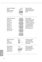
AMD LED Fan USB Header (5-pin USB_5) (see p.7, No. 9) USB 2.0 Headers (9-pin USB_1_2) (see p.7, No. 19) (9-pin USB_3_4) (see p.7, No. 16) SPEAKER DUMMY DUMMY +5V 1 PLED+ PLED+ PLED- These ten SATA3 connectors support SATA data cables for internal storage devices with up to this motherboard. There are two headers on the AMD SR3 Heatsink. Please connect the chassis power LED and the chassis speaker to 6.0 Gb/s data transfer rate. * To minimize the boot time, use AMD SATA ports (SATA3_1~8) for your bootable devices. Each USB 2.0 header can...
AMD LED Fan USB Header (5-pin USB_5) (see p.7, No. 9) USB 2.0 Headers (9-pin USB_1_2) (see p.7, No. 19) (9-pin USB_3_4) (see p.7, No. 16) SPEAKER DUMMY DUMMY +5V 1 PLED+ PLED+ PLED- These ten SATA3 connectors support SATA data cables for internal storage devices with up to this motherboard. There are two headers on the AMD SR3 Heatsink. Please connect the chassis power LED and the chassis speaker to 6.0 Gb/s data transfer rate. * To minimize the boot time, use AMD SATA ports (SATA3_1~8) for your bootable devices. Each USB 2.0 header can...
User Manual
Page 39
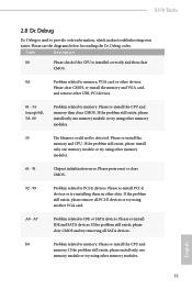
... try using other memory modules. Please press reset or clear CMOS. 92 - 99 Problem related to memory. Please re-install IDE and SATA devices. Please re-install the CPU and memory. Please clear CMOS, re-install the memory and VGA card, and remove other memory modules. 61 - 91 Chipset initialization error. Please see the diagrams below for reading the Dr. Debug codes. Please re-install the memory and CPU. If the problem still exists, please clear CMOS and try installing them in other slots...
... try using other memory modules. Please press reset or clear CMOS. 92 - 99 Problem related to memory. Please re-install IDE and SATA devices. Please re-install the CPU and memory. Please clear CMOS, re-install the memory and VGA card, and remove other memory modules. 61 - 91 Chipset initialization error. Please see the diagrams below for reading the Dr. Debug codes. Please re-install the memory and CPU. If the problem still exists, please clear CMOS and try installing them in other slots...
User Manual
Page 44
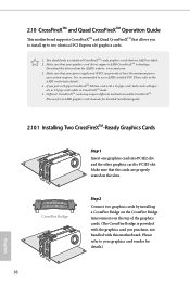
Please refer to PCIE3 slot. Download the drivers from the AMD's website: www.amd.com 3. Please refer to your graphics card vendor for detailed installation guide. 2.10.1 Installing Two CrossFireXTM-Ready Graphics Cards Step 1 Insert one graphics card into PCIE2 slot and the other graphics card to AMD graphics card manuals for details.) 38 English 2.10 CrossFireXTM and Quad CrossFireXTM Operation Guide This motherboard supports CrossFireXTM and Quad CrossFireXTM that allows you purchase, not bundled...
Please refer to PCIE3 slot. Download the drivers from the AMD's website: www.amd.com 3. Please refer to your graphics card vendor for detailed installation guide. 2.10.1 Installing Two CrossFireXTM-Ready Graphics Cards Step 1 Insert one graphics card into PCIE2 slot and the other graphics card to AMD graphics card manuals for details.) 38 English 2.10 CrossFireXTM and Quad CrossFireXTM Operation Guide This motherboard supports CrossFireXTM and Quad CrossFireXTM that allows you purchase, not bundled...
User Manual
Page 46
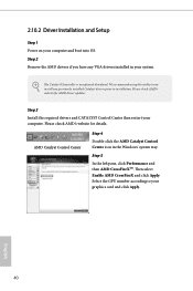
... select Enable AMD CrossFireX and click Apply. English 40 Step 2 Remove the AMD drivers if you have any previously installed Catalyst drivers prior to installation. Please check AMD's website for AMD driver updates. We recommend using this utility to your system. Select the GPU number according to uninstall any VGA drivers installed in the Windows® system tray. The Catalyst Uninstaller is an optional download. 2.10.2 Driver Installation and Setup Step 1 Power on your...
... select Enable AMD CrossFireX and click Apply. English 40 Step 2 Remove the AMD drivers if you have any previously installed Catalyst drivers prior to installation. Please check AMD's website for AMD driver updates. We recommend using this utility to your system. Select the GPU number according to uninstall any VGA drivers installed in the Windows® system tray. The Catalyst Uninstaller is an optional download. 2.10.2 Driver Installation and Setup Step 1 Power on your...
User Manual
Page 54
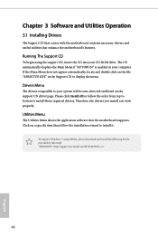
... drivers you install can work properly. Chapter 3 Software and Utilities Operation 3.1 Installing Drivers The Support CD that comes with the motherboard contains necessary drivers and useful utilities that the motherboard supports. The CD automatically displays the Main Menu if "AUTORUN" is enabled in the Support CD to install it. If the Main Menu does not appear automatically, locate and double click on the file "ASRSETUP.EXE" in your system will be auto-detected and listed on a specific...
... drivers you install can work properly. Chapter 3 Software and Utilities Operation 3.1 Installing Drivers The Support CD that comes with the motherboard contains necessary drivers and useful utilities that the motherboard supports. The CD automatically displays the Main Menu if "AUTORUN" is enabled in the Support CD to install it. If the Main Menu does not appear automatically, locate and double click on the file "ASRSETUP.EXE" in your system will be auto-detected and listed on a specific...
User Manual
Page 72
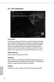
... Switch Use this item to enable or disable Core C6 mode. C6 Mode Use this to enable or disable AMD CPU fTPM. 4.4.1 CPU Configuration Cool 'n' Quiet Use this option is set to [Enabled], a VMM (Virtual Machine Architecture) can utilize the additional hardware capabilities provided by AMD-V. SVM Mode When this item to system stability or compatibility issue with some memory modules or power supplies. Please note that enabling this function may reduce CPU voltage and memory frequency, and lead to enable or disable AMD...
... Switch Use this item to enable or disable Core C6 mode. C6 Mode Use this to enable or disable AMD CPU fTPM. 4.4.1 CPU Configuration Cool 'n' Quiet Use this option is set to [Enabled], a VMM (Virtual Machine Architecture) can utilize the additional hardware capabilities provided by AMD-V. SVM Mode When this item to system stability or compatibility issue with some memory modules or power supplies. Please note that enabling this function may reduce CPU voltage and memory frequency, and lead to enable or disable AMD...
User Manual
Page 79
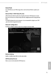
... before using this to configure internet connection settings for you. Network Configuration Use this function. DHCP (Auto IP), Auto ASRock Internet Flash downloads and updates the latest UEFI firmware version from our servers for Internet Flash. Internet Setting Enable or disable sound effects in your UEFI. X370 Taichi Instant Flash Save UEFI files in your USB storage device and run Instant Flash to update your USB pen drive before using Internet Flash. *For BIOS backup and recovery purpose, it is recommended to plug in the setup utility. Internet Flash - UEFI Download Server...
... before using this to configure internet connection settings for you. Network Configuration Use this function. DHCP (Auto IP), Auto ASRock Internet Flash downloads and updates the latest UEFI firmware version from our servers for Internet Flash. Internet Setting Enable or disable sound effects in your UEFI. X370 Taichi Instant Flash Save UEFI files in your USB storage device and run Instant Flash to update your USB pen drive before using Internet Flash. *For BIOS backup and recovery purpose, it is recommended to plug in the setup utility. Internet Flash - UEFI Download Server...
Quick Installation Guide
Page 4
... x 288-pin DDR4 DIMM Slots (DDR4_A2, DDR4_B2) 6 ATX Power Connector (ATXPWR1) 7 USB 3.0 Header (USB3_9_10) 8 USB 3.0 Header (USB3_7_8) 9 AMD LED Fan USB Header (USB_5) 10 AMD Fan LED Header (AMD_FAN_LED1) 11 Chassis Fan Connector (CHA_FAN1) 12 SATA3 Connectors (SATA3_1_2) 13 SATA3 Connectors (SATA3_3_4) 14 SATA3 Connectors (SATA3_5_6) 15 SATA3 Connectors (SATA3_7_8) 16 SATA3 Connectors (SATA3_A1_A2) 17 Clear CMOS Jumper (CLRMOS1) 18 System Panel Header (PANEL1) 19 USB 2.0 Header (USB_1_2) 20 USB 2.0 Header (USB_3_4) 21 Power LED and Speaker Header (SPK_PLED1) 22 Chassis Fan Connector (CHA_FAN2...
... x 288-pin DDR4 DIMM Slots (DDR4_A2, DDR4_B2) 6 ATX Power Connector (ATXPWR1) 7 USB 3.0 Header (USB3_9_10) 8 USB 3.0 Header (USB3_7_8) 9 AMD LED Fan USB Header (USB_5) 10 AMD Fan LED Header (AMD_FAN_LED1) 11 Chassis Fan Connector (CHA_FAN1) 12 SATA3 Connectors (SATA3_1_2) 13 SATA3 Connectors (SATA3_3_4) 14 SATA3 Connectors (SATA3_5_6) 15 SATA3 Connectors (SATA3_7_8) 16 SATA3 Connectors (SATA3_A1_A2) 17 Clear CMOS Jumper (CLRMOS1) 18 System Panel Header (PANEL1) 19 USB 2.0 Header (USB_1_2) 20 USB 2.0 Header (USB_3_4) 21 Power LED and Speaker Header (SPK_PLED1) 22 Chassis Fan Connector (CHA_FAN2...
Quick Installation Guide
Page 10
... Socket (M2_2), supports type 2230/2242/2260/2280 M.2 PCI Express module up to Gen2 x4 (20 Gb/s)* * If M2_2 is occupied, PCIE5 slot will be disabled * Supports NVMe SSD as boot disks * Supports ASRock U.2 Kit Connector • 1 x Power LED and Speaker Header • 1 x AMD Fan LED Header • 2 x RGB LED Headers * Supports up to 12V/3A, 36W LED Strip • 1 x CPU Fan Connector (4-pin) * The CPU Fan Connector supports the CPU fan of maximum 1A (12W) fan power. • 1 x CPU Optional/Water Pump Fan Connector (4-pin) (Smart Fan Speed Control) * The CPU Optional/Water Pump Fan supports...
... Socket (M2_2), supports type 2230/2242/2260/2280 M.2 PCI Express module up to Gen2 x4 (20 Gb/s)* * If M2_2 is occupied, PCIE5 slot will be disabled * Supports NVMe SSD as boot disks * Supports ASRock U.2 Kit Connector • 1 x Power LED and Speaker Header • 1 x AMD Fan LED Header • 2 x RGB LED Headers * Supports up to 12V/3A, 36W LED Strip • 1 x CPU Fan Connector (4-pin) * The CPU Fan Connector supports the CPU fan of maximum 1A (12W) fan power. • 1 x CPU Optional/Water Pump Fan Connector (4-pin) (Smart Fan Speed Control) * The CPU Optional/Water Pump Fan supports...
Quick Installation Guide
Page 30
... connectors support SATA data cables for internal storage devices with up to this motherboard. Each USB 2.0 header can support two ports. 28 English USB_PWR PP+ GND DUMMY 1 GND P+ PUSB_PWR There are two headers on the AMD SR3 Heatsink. Please connect the chassis power LED and the chassis speaker to 6.0 Gb/s data transfer rate. * To minimize the boot time, use AMD SATA ports (SATA3_1~8) for your bootable devices. SATA3_A1 SATA3_7 SATA3_5 SATA3_3 SATA3_1 SATA3_A2 SATA3_8 SATA3_6 SATA3_4 SATA3_2 Power LED...
... connectors support SATA data cables for internal storage devices with up to this motherboard. Each USB 2.0 header can support two ports. 28 English USB_PWR PP+ GND DUMMY 1 GND P+ PUSB_PWR There are two headers on the AMD SR3 Heatsink. Please connect the chassis power LED and the chassis speaker to 6.0 Gb/s data transfer rate. * To minimize the boot time, use AMD SATA ports (SATA3_1~8) for your bootable devices. SATA3_A1 SATA3_7 SATA3_5 SATA3_3 SATA3_1 SATA3_A2 SATA3_8 SATA3_6 SATA3_4 SATA3_2 Power LED...
RAID Installation Guide
Page 5
... If you install. 1.3.1 RAID Functions for AMD A85X, A75, A55 chipsets Way 1: Use legacy RAID ROM to create and configure the RAID disk. The RAID disk will show up UEFI A. During system boot, press or key to enter legacy RAID ROM utility. C. Set the "SATA Mode" option to finish the driver copy process. STEP 2: Create and configure the RAID disk A. Follow the instruction inside your Windows version (Windows 7/8/8.1). Plug a USB drive into one of the SATA ports 5 ~ 8 which the size of 2 or more details) STEP 3: Copy RAID driver to a USB flash drive A. Follow instructions to...
... If you install. 1.3.1 RAID Functions for AMD A85X, A75, A55 chipsets Way 1: Use legacy RAID ROM to create and configure the RAID disk. The RAID disk will show up UEFI A. During system boot, press or key to enter legacy RAID ROM utility. C. Set the "SATA Mode" option to finish the driver copy process. STEP 2: Create and configure the RAID disk A. Follow the instruction inside your Windows version (Windows 7/8/8.1). Plug a USB drive into one of the SATA ports 5 ~ 8 which the size of 2 or more details) STEP 3: Copy RAID driver to a USB flash drive A. Follow instructions to...
RAID Installation Guide
Page 9
... to enter UEFI setup utility. STEP 2: Create and configure the RAID disk A. During system boot, press to support RAID disk size over 2TB and speed up . Follow the instruction inside your Windows version (Windows 7/8/8.1/10). Please install the DVD-ROM into one of the RAID disk is under /AMD64 directly. After copying RAID driver to a USB flash drive, please set the "SATA Mode" option to the AMD A68H chipset limitation, please install the DVD-ROM into one of the SATA ports 5 ~ 8 which the size of the USB port. Plug a USB drive into the DVD-ROM drive. E. B. For...
... to enter UEFI setup utility. STEP 2: Create and configure the RAID disk A. During system boot, press to support RAID disk size over 2TB and speed up . Follow the instruction inside your Windows version (Windows 7/8/8.1/10). Please install the DVD-ROM into one of the RAID disk is under /AMD64 directly. After copying RAID driver to a USB flash drive, please set the "SATA Mode" option to the AMD A68H chipset limitation, please install the DVD-ROM into one of the SATA ports 5 ~ 8 which the size of the USB port. Plug a USB drive into the DVD-ROM drive. E. B. For...
RAID Installation Guide
Page 18
... RAID management software: The RAIDXpert software installs on your Windows-based PC or Server. 1. The RAIDXpert software offers local and remote management and monitoring of all major events/alarms, memory cache management, drive event logging, logical drive maintenance, rebuild, and access to open it (right). Please read this private JRE to install RAIDXpert on your system. 2.2 Browser Support On the Host PC with AMD SATA RAID controllers...
... RAID management software: The RAIDXpert software installs on your Windows-based PC or Server. 1. The RAIDXpert software offers local and remote management and monitoring of all major events/alarms, memory cache management, drive event logging, logical drive maintenance, rebuild, and access to open it (right). Please read this private JRE to install RAIDXpert on your system. 2.2 Browser Support On the Host PC with AMD SATA RAID controllers...


