User Manual
Page 5
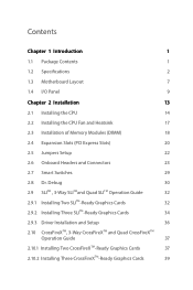
...Package Contents 1 1.2 Specifications 2 1.3 Motherboard Layout 7 1.4 I/O Panel 9 Chapter 2 Installation 13 2.1 Installing the CPU 14 2.2 Installing the CPU Fan and Heatsink 17 2.3 Installation of Memory Modules (DIMM) 18 2.4 Expansion Slots (PCI Express Slots) 20 2.5 Jumpers Setup 22 2.6 Onboard Headers and Connectors 23 2.7 Smart Switches 29 2.8 Dr. Debug 30 2.9 SLITM , 3-Way SLITMand Quad SLITM Operation Guide 32 2.9.1 Installing Two SLITM-Ready Graphics Cards 32 2.9.2 Installing Three SLITM-Ready Graphics Cards 34 2.9.3 Driver Installation and Setup 36 2.10...
...Package Contents 1 1.2 Specifications 2 1.3 Motherboard Layout 7 1.4 I/O Panel 9 Chapter 2 Installation 13 2.1 Installing the CPU 14 2.2 Installing the CPU Fan and Heatsink 17 2.3 Installation of Memory Modules (DIMM) 18 2.4 Expansion Slots (PCI Express Slots) 20 2.5 Jumpers Setup 22 2.6 Onboard Headers and Connectors 23 2.7 Smart Switches 29 2.8 Dr. Debug 30 2.9 SLITM , 3-Way SLITMand Quad SLITM Operation Guide 32 2.9.1 Installing Two SLITM-Ready Graphics Cards 32 2.9.2 Installing Three SLITM-Ready Graphics Cards 34 2.9.3 Driver Installation and Setup 36 2.10...
User Manual
Page 8
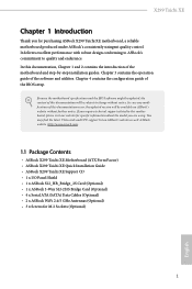
... of the BIOS setup. Chapter 4 contains the configuration guide of the software and utilities. You may find the latest VGA cards and CPU support list on ASRock's website without notice. ASRock website http://www.asrock.com. 1.1 Package Contents • ASRock X299 Taichi XE Motherboard (ATX Form Factor) • ASRock X299 Taichi XE Quick Installation Guide • ASRock X299 Taichi XE Support CD • 1 x I/O Panel Shield • 1 x ASRock SLI_HB_Bridge_2S Card (Optional) • 1 x ASRock 3-Way SLI-2S1S Bridge Card (Optional) • 4 x Serial ATA (SATA) Data Cables (Optional...
... of the BIOS setup. Chapter 4 contains the configuration guide of the software and utilities. You may find the latest VGA cards and CPU support list on ASRock's website without notice. ASRock website http://www.asrock.com. 1.1 Package Contents • ASRock X299 Taichi XE Motherboard (ATX Form Factor) • ASRock X299 Taichi XE Quick Installation Guide • ASRock X299 Taichi XE Support CD • 1 x I/O Panel Shield • 1 x ASRock SLI_HB_Bridge_2S Card (Optional) • 1 x ASRock 3-Way SLI-2S1S Bridge Card (Optional) • 4 x Serial ATA (SATA) Data Cables (Optional...
User Manual
Page 10
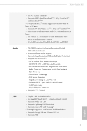
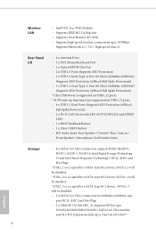
... Audio Connector • Supports DTS Connect • Gigabit LAN 10/100/1000 Mb/s • 1 x Giga PHY Intel® I219V, 1 x GigaLAN Intel® I211AT • Supports Wake-On-LAN • Supports Lightning/ESD Protection • Supports Dual LAN with Content Protection (Realtek ALC1220 Audio Codec) • Premium Blu-ray Audio support • Supports Surge Protection (ASRock Full Spike Protection) • Supports Purity SoundTM 4 - PCB Isolate Shielding - X299 Taichi XE Audio LAN • 1 x PCI Express 2.0 x1 Slot • Supports AMD Quad...
... Audio Connector • Supports DTS Connect • Gigabit LAN 10/100/1000 Mb/s • 1 x Giga PHY Intel® I219V, 1 x GigaLAN Intel® I211AT • Supports Wake-On-LAN • Supports Lightning/ESD Protection • Supports Dual LAN with Content Protection (Realtek ALC1220 Audio Codec) • Premium Blu-ray Audio support • Supports Surge Protection (ASRock Full Spike Protection) • Supports Purity SoundTM 4 - PCB Isolate Shielding - X299 Taichi XE Audio LAN • 1 x PCI Express 2.0 x1 Slot • Supports AMD Quad...
User Manual
Page 11
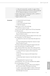
...USB Power is supported on USB3_12 ports. • 4 x USB 3.1 Gen1 Ports (Supports ESD Protection (ASRock Full Spike Protection)) • 2 x RJ-45 LAN Ports with LED (ACT/LINK LED and SPEED LED) • 1 x BIOS Flashback Button • 1 x Clear CMOS Button • HD Audio Jacks: Rear Speaker / Central / Bass / Line in / Front Speaker / Microphone (Gold Audio Jacks) Storage • 8 x SATA3 6.0 Gb/s Connectors, support RAID (RAID 0, RAID 1, RAID 5, RAID 10, Intel Rapid Storage Technology 15 and Intel Smart Response Technology), NCQ, AHCI and Hot Plug* * If M2_1 is occupied by a SATA-type...
...USB Power is supported on USB3_12 ports. • 4 x USB 3.1 Gen1 Ports (Supports ESD Protection (ASRock Full Spike Protection)) • 2 x RJ-45 LAN Ports with LED (ACT/LINK LED and SPEED LED) • 1 x BIOS Flashback Button • 1 x Clear CMOS Button • HD Audio Jacks: Rear Speaker / Central / Bass / Line in / Front Speaker / Microphone (Gold Audio Jacks) Storage • 8 x SATA3 6.0 Gb/s Connectors, support RAID (RAID 0, RAID 1, RAID 5, RAID 10, Intel Rapid Storage Technology 15 and Intel Smart Response Technology), NCQ, AHCI and Hot Plug* * If M2_1 is occupied by a SATA-type...
User Manual
Page 12
...- X299 Taichi XE • 2 x Ultra M.2 Sockets (M2_1 and M2_3), support M Key type 2230/2242/2260/2280 M.2 SATA3 6.0 Gb/s module and M.2 PCI Express module up to Gen3 x4 (32 Gb/s)** ** Supports Intel® OptaneTM Technology (on CPU type). • 2 x USB 2.0 Headers (Support 4 USB 2.0 ports) (Supports ESD Protection (ASRock Full Spike Protection)) • 2 x USB 3.1 Gen1 Headers (Support 4 USB 3.1 Gen1 ports) (ASMedia ASM1074 Hub) (Supports ESD Protection (ASRock Full Spike Protection)) 5 English trol) • 1 x Chassis Optional/Water Pump Fan Connector (4-pin) (Smart Fan Speed...
...- X299 Taichi XE • 2 x Ultra M.2 Sockets (M2_1 and M2_3), support M Key type 2230/2242/2260/2280 M.2 SATA3 6.0 Gb/s module and M.2 PCI Express module up to Gen3 x4 (32 Gb/s)** ** Supports Intel® OptaneTM Technology (on CPU type). • 2 x USB 2.0 Headers (Support 4 USB 2.0 ports) (Supports ESD Protection (ASRock Full Spike Protection)) • 2 x USB 3.1 Gen1 Headers (Support 4 USB 3.1 Gen1 ports) (ASMedia ASM1074 Hub) (Supports ESD Protection (ASRock Full Spike Protection)) 5 English trol) • 1 x Chassis Optional/Water Pump Fan Connector (4-pin) (Smart Fan Speed...
User Manual
Page 14
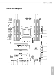
1.3 Motherboard Layout X299 Taichi XE 12 3 4 56 7 USB 2.0 T: USB1 B: USB2 PS2 Keyboard /Mouse M2_WIFI_1 BIOS _FB1 CLRC BTN1 USB 3.1 Gen1 Top: T: USB1 B: USB2 RJ-45 LAN USB 3.1 Gen1 T: USB3 Top: B: USB4 RJ-45 ATX12V2 ATX12V1 2066 Socket CPU_FAN1 1 8 RGB_LED2 9 ATXPWR1 DDR4_C2 (64 bit, 288-pin module) DDR4_C1 (64 bit, 288-pin module) DDR4_D2 (64 bit, 288-pin module) DDR4_D1 (64 bit, 288-pin module) DDR4_B1 (64 bit, 288-pin module) DDR4_B2 (64 bit, 288...
1.3 Motherboard Layout X299 Taichi XE 12 3 4 56 7 USB 2.0 T: USB1 B: USB2 PS2 Keyboard /Mouse M2_WIFI_1 BIOS _FB1 CLRC BTN1 USB 3.1 Gen1 Top: T: USB1 B: USB2 RJ-45 LAN USB 3.1 Gen1 T: USB3 Top: B: USB4 RJ-45 ATX12V2 ATX12V1 2066 Socket CPU_FAN1 1 8 RGB_LED2 9 ATXPWR1 DDR4_C2 (64 bit, 288-pin module) DDR4_C1 (64 bit, 288-pin module) DDR4_D2 (64 bit, 288-pin module) DDR4_D1 (64 bit, 288-pin module) DDR4_B1 (64 bit, 288-pin module) DDR4_B2 (64 bit, 288...
User Manual
Page 15
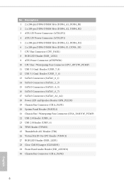
...) 14 SATA3 Connectors (SATA3_2_3) 15 SATA3 Connectors (SATA3_4_5) 16 SATA3 Connectors (SATA3_6_7) 17 SATA3 Connectors (SATA3_A1_A2) 18 Power LED and Speaker Header (SPK_PLED1) 19 Chassis Fan Connector (CHA_FAN1) 20 System Panel Header (PANEL1) 21 Chassis Fan / Waterpump Fan Connector (CHA_FAN3/W_PUMP) 22 USB 2.0 Header (USB5_6) 23 USB 2.0 Header (USB3_4) 24 TPM Header (TPMS1) 25 Thunderbolt AIC Header (TB1) 26 Virtual RAID On CPU Header (VROC1) 27 RGB LED Header (RGB_LED1) 28 Clear CMOS Jumper (CLRMOS1) 29 Front Panel Audio Header (HD_AUDIO1) 30 Chassis Fan Connector (CHA_FAN2) 8 English...
...) 14 SATA3 Connectors (SATA3_2_3) 15 SATA3 Connectors (SATA3_4_5) 16 SATA3 Connectors (SATA3_6_7) 17 SATA3 Connectors (SATA3_A1_A2) 18 Power LED and Speaker Header (SPK_PLED1) 19 Chassis Fan Connector (CHA_FAN1) 20 System Panel Header (PANEL1) 21 Chassis Fan / Waterpump Fan Connector (CHA_FAN3/W_PUMP) 22 USB 2.0 Header (USB5_6) 23 USB 2.0 Header (USB3_4) 24 TPM Header (TPMS1) 25 Thunderbolt AIC Header (TB1) 26 Virtual RAID On CPU Header (VROC1) 27 RGB LED Header (RGB_LED1) 28 Clear CMOS Jumper (CLRMOS1) 29 Front Panel Audio Header (HD_AUDIO1) 30 Chassis Fan Connector (CHA_FAN2) 8 English...
User Manual
Page 28
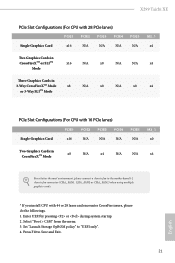
Select "Boot > CSM" from the menu. 3. Set "Launch Storage OpROM policy" to Save and Exit. 21 English Press F10 to "UEFI only". 4. Enter UEFI by pressing or during system startup. 2. X299 Taichi XE PCIe Slot Configurations (For CPU with 28 PCIe lanes) PCIE1 PCIE2 PCIE3 PCIE4 Single Graphics Card x16 N/A N/A N/A PCIE5 N/A M2_1 x4 Two Graphics Cards in CrossFireXTM or SLITM Mode x16 N/A x8 N/A N/A x4 Three Graphics Cards in 3-Way CrossFireXTM Mode x8 N/A x8 N/A x8...
Select "Boot > CSM" from the menu. 3. Set "Launch Storage OpROM policy" to Save and Exit. 21 English Press F10 to "UEFI only". 4. Enter UEFI by pressing or during system startup. 2. X299 Taichi XE PCIe Slot Configurations (For CPU with 28 PCIe lanes) PCIE1 PCIE2 PCIE3 PCIE4 Single Graphics Card x16 N/A N/A N/A PCIE5 N/A M2_1 x4 Two Graphics Cards in CrossFireXTM or SLITM Mode x16 N/A x8 N/A N/A x4 Three Graphics Cards in 3-Way CrossFireXTM Mode x8 N/A x8 N/A x8...
User Manual
Page 30
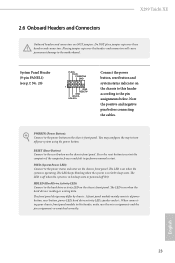
... chassis front panel. Do NOT place jumper caps over the headers and connectors will cause permanent damage to the pin assignments below. PWRBTN (Power Button): Connect to the power button on the chassis to this header, make sure the wire assignments and the pin assignments are NOT jumpers. HDLED (Hard Drive Activity LED): Connect to perform a normal restart. X299 Taichi XE 2.6 Onboard Headers and Connectors Onboard headers and connectors are matched correctly. Note the positive and negative pins before connecting the cables...
... chassis front panel. Do NOT place jumper caps over the headers and connectors will cause permanent damage to the pin assignments below. PWRBTN (Power Button): Connect to the power button on the chassis to this header, make sure the wire assignments and the pin assignments are NOT jumpers. HDLED (Hard Drive Activity LED): Connect to perform a normal restart. X299 Taichi XE 2.6 Onboard Headers and Connectors Onboard headers and connectors are matched correctly. Note the positive and negative pins before connecting the cables...
User Manual
Page 32
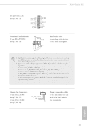
... AC'97 audio panel. You don't need to the front panel audio header by the steps below: A. English 25 High Definition Audio supports Jack Sensing, but the panel wire on the chassis must support HDA to the ground pin. B. D. Chassis Fan Connectors (4-pin CHA_FAN1) (see p.7, No. 19) (4-pin CHA_FAN2) (see p.7, No. 29) GND PRESENCE# MIC_RET OUT_RET 1 OUT2_L J_SENSE OUT2_R MIC2_R MIC2_L This header is for connecting audio devices to OUT2_L. X299 Taichi XE (19-pin USB3_7_8...
... AC'97 audio panel. You don't need to the front panel audio header by the steps below: A. English 25 High Definition Audio supports Jack Sensing, but the panel wire on the chassis must support HDA to the ground pin. B. D. Chassis Fan Connectors (4-pin CHA_FAN1) (see p.7, No. 19) (4-pin CHA_FAN2) (see p.7, No. 29) GND PRESENCE# MIC_RET OUT_RET 1 OUT2_L J_SENSE OUT2_R MIC2_R MIC2_L This header is for connecting audio devices to OUT2_L. X299 Taichi XE (19-pin USB3_7_8...
User Manual
Page 34
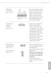
... helps enhance network security, protects digital identities, and ensures platform integrity. These two RGB headers are used to connect RGB LED extension cable which can be damaged. *Please refer to page 57 for further instructions on CPU type). English 27 otherwise, the cable may be installed in the wrong orientation; If you install CPU with 44 lanes, install the card to PCIE2. X299 Taichi XE TPM Header (17-pin TPMS1...
... helps enhance network security, protects digital identities, and ensures platform integrity. These two RGB headers are used to connect RGB LED extension cable which can be damaged. *Please refer to page 57 for further instructions on CPU type). English 27 otherwise, the cable may be installed in the wrong orientation; If you install CPU with 44 lanes, install the card to PCIE2. X299 Taichi XE TPM Header (17-pin TPMS1...
User Manual
Page 36
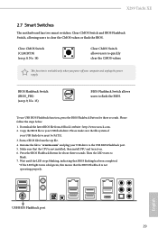
... LED light turns solid green, this means that the CPU is not installed; To use USB BIOS Flashback function, press the BIOS Flashback Button for about three seconds. Please follow the steps below. 1. X299 Taichi XE 2.7 Smart Switches The motherboard has two smart switches: Clear CMOS Switch and BIOS Flashback Switch, allowing users to quickly clear the CMOS values. Please make sure the file system of your computer and unplug the power supply. Extract BIOS file from ASRock's website : http://www.asrock.com. 2. Clear CMOS Switch...
... LED light turns solid green, this means that the CPU is not installed; To use USB BIOS Flashback function, press the BIOS Flashback Button for about three seconds. Please follow the steps below. 1. X299 Taichi XE 2.7 Smart Switches The motherboard has two smart switches: Clear CMOS Switch and BIOS Flashback Switch, allowing users to quickly clear the CMOS values. Please make sure the file system of your computer and unplug the power supply. Extract BIOS file from ASRock's website : http://www.asrock.com. 2. Clear CMOS Switch...
User Manual
Page 37
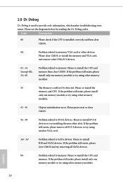
... problem still exists, please install only one memory module or try using other memory modules. Please re-install PCI-E devices or try using other slots. b0 Problem related to memory, VGA card or other USB, PCI devices. 01 - 54 (except 0d), 5A- 60 Problem related to PCI-E devices. Code Description 00 Please check if the CPU is used to SATA devices. Please press reset or clear CMOS. 92 - 99 Problem related to memory. If the problem still exists, please install only one memory...
... problem still exists, please install only one memory module or try using other memory modules. Please re-install PCI-E devices or try using other slots. b0 Problem related to memory, VGA card or other USB, PCI devices. 01 - 54 (except 0d), 5A- 60 Problem related to PCI-E devices. Code Description 00 Please check if the CPU is used to SATA devices. Please press reset or clear CMOS. 92 - 99 Problem related to memory. If the problem still exists, please install only one memory...
User Manual
Page 44
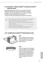
... to three identical PCI Express x16 graphics cards. Please refer to enable CrossFireXTM. Currently CrossFireXTM, 3-way CrossFireXTM and Quad CrossFireXTM are AMD certified. 2. It is only supported with CPU with a 16-pipe card, both cards will operate as 12-pipe cards while in CrossFireXTM mode. 5. Make sure that your system requires. X299 Taichi XE 2.10 CrossFireXTM, 3-Way CrossFireXTM and Quad CrossFireXTM Operation Guide This motherboard supports CrossFireXTM, 3-way...
... to three identical PCI Express x16 graphics cards. Please refer to enable CrossFireXTM. Currently CrossFireXTM, 3-way CrossFireXTM and Quad CrossFireXTM are AMD certified. 2. It is only supported with CPU with a 16-pipe card, both cards will operate as 12-pipe cards while in CrossFireXTM mode. 5. Make sure that your system requires. X299 Taichi XE 2.10 CrossFireXTM, 3-Way CrossFireXTM and Quad CrossFireXTM Operation Guide This motherboard supports CrossFireXTM, 3-way...
User Manual
Page 47
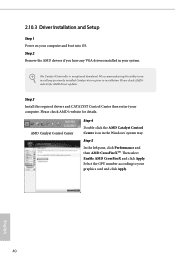
We recommend using this utility to uninstall any VGA drivers installed in the Windows® system tray. Step 3 Install the required drivers and CATALYST Control Center then restart your computer and boot into OS. English 40 Please check AMD's website for details. Then select Enable AMD CrossFireX and click Apply. Step 5 In the left pane, click Performance and then AMD CrossFireXTM. Step 2 Remove the AMD drivers if you...
We recommend using this utility to uninstall any VGA drivers installed in the Windows® system tray. Step 3 Install the required drivers and CATALYST Control Center then restart your computer and boot into OS. English 40 Please check AMD's website for details. Then select Enable AMD CrossFireX and click Apply. Step 5 In the left pane, click Performance and then AMD CrossFireXTM. Step 2 Remove the AMD drivers if you...

User Manual
Page 52
... Support CD to install those required drivers. If the Main Menu does not appear automatically, locate and double click on the file "ASRSETUP.EXE" in your system will be auto-detected and listed on a specific item then follow the order from top to bottom to display the menu. Please click Install All or follow the installation wizard to your computer. X299 Taichi XE Chapter 3 Software and Utilities Operation 3.1 Installing Drivers The Support...
... Support CD to install those required drivers. If the Main Menu does not appear automatically, locate and double click on the file "ASRSETUP.EXE" in your system will be auto-detected and listed on a specific item then follow the order from top to bottom to display the menu. Please click Install All or follow the installation wizard to your computer. X299 Taichi XE Chapter 3 Software and Utilities Operation 3.1 Installing Drivers The Support...
User Manual
Page 86
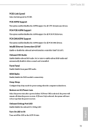
... Panel Enable/disable front panel HD audio. PCH PCIE ASPM Support This option enables/disables the ASPM support for all PCH DMI devices. Onboard Debug Port LED Enable/disable the onboard Dr. Debug LED. PCH DMI ASPM Support This option enables/disables the ASPM support for all CPU downstream devices. X299 Taichi XE PCIE5 Link Speed Select the link speed for power saving when the computer is shut down. Set to Auto to boot up when the power recovers. Deep Sleep Configure deep sleep mode for PCIE5. If [Power Off] is installed. Turn...
... Panel Enable/disable front panel HD audio. PCH PCIE ASPM Support This option enables/disables the ASPM support for all PCH DMI devices. Onboard Debug Port LED Enable/disable the onboard Dr. Debug LED. PCH DMI ASPM Support This option enables/disables the ASPM support for all CPU downstream devices. X299 Taichi XE PCIE5 Link Speed Select the link speed for power saving when the computer is shut down. Set to Auto to boot up when the power recovers. Deep Sleep Configure deep sleep mode for PCIE5. If [Power Off] is installed. Turn...
User Manual
Page 94
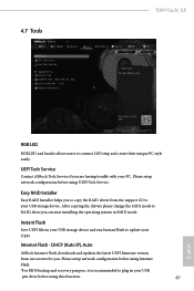
... for you are having trouble with your USB storage device. After copying the drivers please change the SATA mode to your PC. DHCP (Auto IP), Auto ASRock Internet Flash downloads and updates the latest UEFI firmware version from the support CD to RAID, then you can start installing the operating system in your UEFI. UEFI Tech Service Contact ASRock Tech Service if you . Please setup network configuration before using UEFI Tech Service. 4.7 Tools X299 Taichi XE RGB LED RGB LED and header allows users to connect LED strip and create their...
... for you are having trouble with your USB storage device. After copying the drivers please change the SATA mode to your PC. DHCP (Auto IP), Auto ASRock Internet Flash downloads and updates the latest UEFI firmware version from the support CD to RAID, then you can start installing the operating system in your UEFI. UEFI Tech Service Contact ASRock Tech Service if you . Please setup network configuration before using UEFI Tech Service. 4.7 Tools X299 Taichi XE RGB LED RGB LED and header allows users to connect LED strip and create their...
User Manual
Page 95
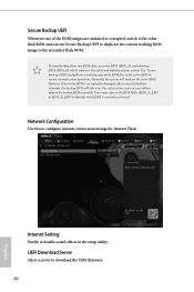
However if the active BIOS is currently activated. Internet Setting Enable or disable sound effects in the setup utility. Use "Secure Backup UEFI" to duplicate a working ROM image to configure internet connection settings for Internet Flash. Normally, the system will take over. UEFI Download Server Select a server to ensure normal system operation. Network Configuration Use this to the secondary flash ROM. Users may refer to the BIOS LEDs (BIOS_A_LED or BIOS_B_LED) to identify which enhances the...
However if the active BIOS is currently activated. Internet Setting Enable or disable sound effects in the setup utility. Use "Secure Backup UEFI" to duplicate a working ROM image to configure internet connection settings for Internet Flash. Normally, the system will take over. UEFI Download Server Select a server to ensure normal system operation. Network Configuration Use this to the secondary flash ROM. Users may refer to the BIOS LEDs (BIOS_A_LED or BIOS_B_LED) to identify which enhances the...
User Manual
Page 99
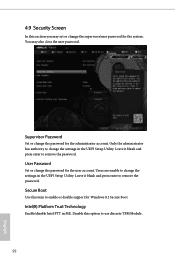
... enter to remove the password. Leave it blank and press enter to remove the password. Secure Boot Use this item to change the settings in the UEFI Setup Utility. Supervisor Password Set or change the supervisor/user password for Windows 8.1 Secure Boot. Intel(R) Platform Trust Technology Enable/disable Intel PTT in the UEFI Setup Utility. 4.9 Security Screen In this section you may also clear the user password. Only the administrator has authority to enable or disable support for the system. Users are unable to use...
... enter to remove the password. Leave it blank and press enter to remove the password. Secure Boot Use this item to change the settings in the UEFI Setup Utility. Supervisor Password Set or change the supervisor/user password for Windows 8.1 Secure Boot. Intel(R) Platform Trust Technology Enable/disable Intel PTT in the UEFI Setup Utility. 4.9 Security Screen In this section you may also clear the user password. Only the administrator has authority to enable or disable support for the system. Users are unable to use...


