
User Manual
Page 3
Contents 1 Introduction 5 1.1 Package Contents 5 1.2 Specifications 6 1.3 Motherboard Layout 10 1.4 ASRock 6CH I/O PlusTM 11 2 Installation 12 2.1 Screw Holes 12 2.2 Pre-installation Precautions 12 2.3 CPU Installation 13 2.4 Installation of ... ATA (SATA) / Serial ATAII (SATAII) Hard Disks Installation 24 2.11 Driver Installation Guide 24 2.12 Untied Overclocking Technology 24 3 BIOS SETUP UTILITY 25 3.1 Introduction 25 3.1.1 BIOS Menu Bar 25 3.1.2 Navigation Keys 26 3.2 Main Screen 26 3.3 Advanced Screen 26 3.3.1 CPU Configuration 27 3.3.2 Chipset Configuration 29 3.3.3 ACPI...
Contents 1 Introduction 5 1.1 Package Contents 5 1.2 Specifications 6 1.3 Motherboard Layout 10 1.4 ASRock 6CH I/O PlusTM 11 2 Installation 12 2.1 Screw Holes 12 2.2 Pre-installation Precautions 12 2.3 CPU Installation 13 2.4 Installation of ... ATA (SATA) / Serial ATAII (SATAII) Hard Disks Installation 24 2.11 Driver Installation Guide 24 2.12 Untied Overclocking Technology 24 3 BIOS SETUP UTILITY 25 3.1 Introduction 25 3.1.1 BIOS Menu Bar 25 3.1.2 Navigation Keys 26 3.2 Main Screen 26 3.3 Advanced Screen 26 3.3.1 CPU Configuration 27 3.3.2 Chipset Configuration 29 3.3.3 ACPI...

User Manual
Page 5
... x 8.7-in, 24.4 cm x 22.1 cm) ASRock Wolfdale1333-D667 Quick Installation Guide ASRock Wolfdale1333-D667 Support CD One 80-conductor Ultra ATA 66/100 IDE Ribbon Cable One Ribbon Cable for purchasing ASRock Wolfdale1333-D667 motherboard, a reliable motherboard produced under ASRock's consistently stringent quality control. It delivers excellent performance with robust design conforming to ASRock's commitment to BIOS setup and information of the...
... x 8.7-in, 24.4 cm x 22.1 cm) ASRock Wolfdale1333-D667 Quick Installation Guide ASRock Wolfdale1333-D667 Support CD One 80-conductor Ultra ATA 66/100 IDE Ribbon Cable One Ribbon Cable for purchasing ASRock Wolfdale1333-D667 motherboard, a reliable motherboard produced under ASRock's consistently stringent quality control. It delivers excellent performance with robust design conforming to ASRock's commitment to BIOS setup and information of the...
User Manual
Page 7
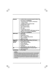
... USB 2.0 ports; Supports jumperfree - Chassis Temperature Sensing - We are not responsible for RAID and "Hot Plug" functions) (see CAUTION 12) - 4Mb AMI BIOS - shared with overclocking, including adjusting the setting in header - Supports "Plug and Play" - Chassis Fan Tachometer - Voltage Monitoring: +12V, +5V, +3.3V... Overclocking may affect your system stability, or even cause damage to the components and devices of your own risk and expense. AMI Legal BIOS - ACPI 1.1 Compliance Wake Up Events - Microsoft® Windows® 2000 / XP / XP 64-bit / VistaTM / VistaTM 64...
... USB 2.0 ports; Supports jumperfree - Chassis Temperature Sensing - We are not responsible for RAID and "Hot Plug" functions) (see CAUTION 12) - 4Mb AMI BIOS - shared with overclocking, including adjusting the setting in header - Supports "Plug and Play" - Chassis Fan Tachometer - Voltage Monitoring: +12V, +5V, +3.3V... Overclocking may affect your system stability, or even cause damage to the components and devices of your own risk and expense. AMI Legal BIOS - ACPI 1.1 Compliance Wake Up Events - Microsoft® Windows® 2000 / XP / XP 64-bit / VistaTM / VistaTM 64...
User Manual
Page 10
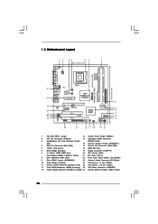
... Core CPU PARALLEL PORT COM1 VGA1 USB2_3 1 27 26 25 24 23 22 21 Top: Line In Center: Line Out Bottom: Mic In Dual Channel Wolfdale1333-D667 USB 2.0 T: USB2 B: USB3 USB 2.0 T: USB0 B: USB1 Top: RJ-45 USB 2.0 T: USB4 B: USB5 USB2.0 Super IO CPU_FAN1 1 IR1 ATXPWR1 Intel 945GC A2 ...Chipset LAN PHY CD1 1 HD_AUDIO1 AUDIO CODEC PCIE2 PCIE1 PCI EXPRESS PCI1 PCI2 1 WIFI 5.1CH HD FLOPPY1 RoHS Intel ICH7 SATAII 4Mb BIOS CHA_FAN1 SPEAKER1 1 IDE1 CMOS Battery CLRCMOS1 SATAII_3 SATAII_1 SATAII_2 SATAII_4 PANEL 1 PLED PWRBTN 1 HDLED RESET 20 19 18 17 16 15 14 24....
... Core CPU PARALLEL PORT COM1 VGA1 USB2_3 1 27 26 25 24 23 22 21 Top: Line In Center: Line Out Bottom: Mic In Dual Channel Wolfdale1333-D667 USB 2.0 T: USB2 B: USB3 USB 2.0 T: USB0 B: USB1 Top: RJ-45 USB 2.0 T: USB4 B: USB5 USB2.0 Super IO CPU_FAN1 1 IR1 ATXPWR1 Intel 945GC A2 ...Chipset LAN PHY CD1 1 HD_AUDIO1 AUDIO CODEC PCIE2 PCIE1 PCI EXPRESS PCI1 PCI2 1 WIFI 5.1CH HD FLOPPY1 RoHS Intel ICH7 SATAII 4Mb BIOS CHA_FAN1 SPEAKER1 1 IDE1 CMOS Battery CLRCMOS1 SATAII_3 SATAII_1 SATAII_2 SATAII_4 PANEL 1 PLED PWRBTN 1 HDLED RESET 20 19 18 17 16 15 14 24....

User Manual
Page 17
... for the card before you install the add-on PCI Express VGA card to PCIE1 (PCIE x16 slot) and adjust the "Internal Graphics Mode Select" BIOS option to [Enabled], the onboard VGA will be enabled, and the primary screen will be onboard VGA. Step 2. Remove the bracket facing the slot that...
... for the card before you install the add-on PCI Express VGA card to PCIE1 (PCIE x16 slot) and adjust the "Internal Graphics Mode Select" BIOS option to [Enabled], the onboard VGA will be enabled, and the primary screen will be onboard VGA. Step 2. Remove the bracket facing the slot that...
User Manual
Page 21
C. E. Enter BIOS Setup Utility. For Windows® 2000 / XP / XP 64-bit OS: Click "Audio I/O", select "Connector Settings" , choose "Disable front panel jack detection", and save the ...
C. E. Enter BIOS Setup Utility. For Windows® 2000 / XP / XP 64-bit OS: Click "Audio I/O", select "Connector Settings" , choose "Disable front panel jack detection", and save the ...
User Manual
Page 24
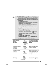
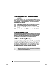
...-detected and listed on the support CD driver page. Please follow the order from [Auto] to [CPU, PCIE, Async.]. STEP 4: Connect the other end of BIOS setup to set the selection from up to bottom side to your chassis. Before you apply Untied Overclocking Technology. 24 STEP 2: Connect the SATA power...
...-detected and listed on the support CD driver page. Please follow the order from [Auto] to [CPU, PCIE, Async.]. STEP 4: Connect the other end of BIOS setup to set the selection from up to bottom side to your chassis. Before you apply Untied Overclocking Technology. 24 STEP 2: Connect the SATA power...

User Manual
Page 25
... Bar The top of the screen has a menu bar with its test routines. Chapter 3 BIOS SETUP UTILITY 3.1 Introduction This section explains how to use the BIOS SETUP UTILITY to enter the BIOS SETUP UTILITY after POST, restart the system by pressing + + , or by turning the system off and then back on the ... is constantly being updated, the following selections: Main To set up the system time/date information Advanced To set up the advanced BIOS features PCIPnP To set up the PCI features Boot To set up the default system device to locate and load the Operating System Security To ...
... Bar The top of the screen has a menu bar with its test routines. Chapter 3 BIOS SETUP UTILITY 3.1 Introduction This section explains how to use the BIOS SETUP UTILITY to enter the BIOS SETUP UTILITY after POST, restart the system by pressing + + , or by turning the system off and then back on the ... is constantly being updated, the following selections: Main To set up the system time/date information Advanced To set up the advanced BIOS features PCIPnP To set up the PCI features Boot To set up the default system device to locate and load the Operating System Security To ...

User Manual
Page 26
... [Hour:Minute:Second] Use this section, you may set the configurations for the following table for all the settings To save changes and exit the BIOS SETUP UTILITY To jump to the Exit Screen or exit the current screen 3.2 Main Screen When you enter the... UTILITY H/W Monitor Boot System Overview System Time System Date [14:00:09] [Thu 10/25/2007] BIOS Version : Wolfdale1333-D667 P1.00 Processor Type : Intel (R) CPU 3.40 GHz (64bit) Processor Speed : 3400 MHz Microcode Update : F34/17 Cache Size : 1024KB Total Memory DDRII1 DDRII2 : 512MB ...
... [Hour:Minute:Second] Use this section, you may set the configurations for the following table for all the settings To save changes and exit the BIOS SETUP UTILITY To jump to the Exit Screen or exit the current screen 3.2 Main Screen When you enter the... UTILITY H/W Monitor Boot System Overview System Time System Date [14:00:09] [Thu 10/25/2007] BIOS Version : Wolfdale1333-D667 P1.00 Processor Type : Intel (R) CPU 3.40 GHz (64bit) Processor Speed : 3400 MHz Microcode Update : F34/17 Cache Size : 1024KB Total Memory DDRII1 DDRII2 : 512MB ...
User Manual
Page 27
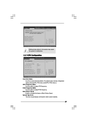
... (C) Copyright 1985-2005, American Megatrends, Inc. PCIE Frequency (MHz) Use this to adjust PCIE frequency. BIOS SETUP UTILITY Main Advanced H/W Monitor Boot Security Exit Advanced Settings WARNING : Setting wrong values in this option to malfunction. 3.3.1 CPU ...Configuration BIOS SETUP UTILITY Advanced CPU Configuration Overclock Mode CPU Frequency (MHz) PCIE Frequency (MHz) Boot Failure Guard Spread Spectrum Ratio Actual ...
... (C) Copyright 1985-2005, American Megatrends, Inc. PCIE Frequency (MHz) Use this to adjust PCIE frequency. BIOS SETUP UTILITY Main Advanced H/W Monitor Boot Security Exit Advanced Settings WARNING : Setting wrong values in this option to malfunction. 3.3.1 CPU ...Configuration BIOS SETUP UTILITY Advanced CPU Configuration Overclock Mode CPU Frequency (MHz) PCIE Frequency (MHz) Boot Failure Guard Spread Spectrum Ratio Actual ...
User Manual
Page 29
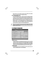
... be hidden if the current CPU does not support Intel (R) SpeedStep(tm) tech.. Please set this item to [Disable] if above issue occurs. 3.3.2 Chipset Configuration BIOS SETUP UTILITY Advanced Chipset Configuration DRAM Frequency [Auto] Flexibility Option [Disabled] DRAM CAS# Latency [Auto] DRAM RAS# to CAS# Delay [Auto] DRAM RAS# Precharge [Auto...
... be hidden if the current CPU does not support Intel (R) SpeedStep(tm) tech.. Please set this item to [Disable] if above issue occurs. 3.3.2 Chipset Configuration BIOS SETUP UTILITY Advanced Chipset Configuration DRAM Frequency [Auto] Flexibility Option [Disabled] DRAM CAS# Latency [Auto] DRAM RAS# to CAS# Delay [Auto] DRAM RAS# Precharge [Auto...

User Manual
Page 32
... Ring-In signals to set this option to [Enabled] if you plan to use this motherboard to boot up when the power recovers. 3.3.3 ACPI Configuration BIOS SETUP UTILITY Advanced ACPI Configuration Suspend To RAM Restore on the system from the power-soft-off when the power recovers. The default value is...
... Ring-In signals to set this option to [Enabled] if you plan to use this motherboard to boot up when the power recovers. 3.3.3 ACPI Configuration BIOS SETUP UTILITY Advanced ACPI Configuration Suspend To RAM Restore on the system from the power-soft-off when the power recovers. The default value is...

User Manual
Page 33
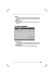
... 3, IDE 1], and [IDE 1, SATA 2, SATA 4]. Because Intel® ICH7 south bridge only supports four IDE devices under legacy OS (Windows NT), you specify. 3.3.4 IDE Configuration BIOS SETUP UTILITY Advanced IDE Configuration ATA/IDE Configuration SATAII 1 SATAII 2 SATAII 3 SATAII 4 IDE1 Master IDE1 Slave [Enhanced] [Hard Disk] [Not Detected] [Not Detected] [Not Detected...
... 3, IDE 1], and [IDE 1, SATA 2, SATA 4]. Because Intel® ICH7 south bridge only supports four IDE devices under legacy OS (Windows NT), you specify. 3.3.4 IDE Configuration BIOS SETUP UTILITY Advanced IDE Configuration ATA/IDE Configuration SATAII 1 SATAII 2 SATAII 3 SATAII 4 IDE1 Master IDE1 Slave [Enhanced] [Hard Disk] [Not Detected] [Not Detected] [Not Detected...

User Manual
Page 34
After selecting the hard disk information into BIOS, use of device connected to enhance hard disk performance by reading or writing more data during each transfer. PIO Mode Use this item to set ...-2 :Ultra DMA-5 :Supported [Auto] [Auto] [Auto] [Auto] [Auto] [Disabled] [Enabled] Select the type of IDE device. [Auto]: Select [Auto] to disable the LBA/Large mode. BIOS SETUP UTILITY Advanced Primary IDE Master Device Vendor Size LBA Mode Block Mode PIO Mode Async DMA Ultra DMA S.M.A.R.T. This is enabled, it will enhance...
After selecting the hard disk information into BIOS, use of device connected to enhance hard disk performance by reading or writing more data during each transfer. PIO Mode Use this item to set ...-2 :Ultra DMA-5 :Supported [Auto] [Auto] [Auto] [Auto] [Auto] [Disabled] [Enabled] Select the type of IDE device. [Auto]: Select [Auto] to disable the LBA/Large mode. BIOS SETUP UTILITY Advanced Primary IDE Master Device Vendor Size LBA Mode Block Mode PIO Mode Async DMA Ultra DMA S.M.A.R.T. This is enabled, it will enhance...
User Manual
Page 35
... feature. 35 Configuration options: [Disabled], [Auto], [Enabled]. 32-Bit Data Transfer Use this item to maximize the IDE hard disk data transfer rate. 3.3.5 PCIPnP Configuration BIOS SETUP UTILITY Advanced Advanced PCI / PnP Settings PCI Latency Timer PCI IDE BusMaster [32] [Enabled] Value in units of PCI clocks for PCI device latency...
... feature. 35 Configuration options: [Disabled], [Auto], [Enabled]. 32-Bit Data Transfer Use this item to maximize the IDE hard disk data transfer rate. 3.3.5 PCIPnP Configuration BIOS SETUP UTILITY Advanced Advanced PCI / PnP Settings PCI Latency Timer PCI IDE BusMaster [32] [Enabled] Value in units of PCI clocks for PCI device latency...
User Manual
Page 36
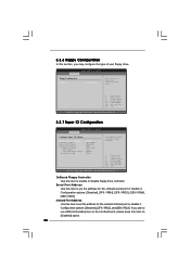
...Option General Help Load Defaults Save and Exit Exit v02.54 (C) Copyright 1985-2005, American Megatrends, Inc. 3.3.7 Super IO Configuration BIOS SETUP UTILITY Advanced Configure Super IO Chipset OnBoard Floppy Controller Serial Port Address Infrared Port Address Parallel Port Address Parallel Port Mode EPP ...Save and Exit Exit v02.54 (C) Copyright 1985-2005, American Megatrends, Inc. 3.3.6 Floppy Configuration In this section, you plan to use ASRock DeskExpress on this motherboard, please keep this item on [Disabled] option. 36 Serial Port Address Use this item to set the address for...
...Option General Help Load Defaults Save and Exit Exit v02.54 (C) Copyright 1985-2005, American Megatrends, Inc. 3.3.7 Super IO Configuration BIOS SETUP UTILITY Advanced Configure Super IO Chipset OnBoard Floppy Controller Serial Port Address Infrared Port Address Parallel Port Address Parallel Port Mode EPP ...Save and Exit Exit v02.54 (C) Copyright 1985-2005, American Megatrends, Inc. 3.3.6 Floppy Configuration In this section, you plan to use ASRock DeskExpress on this motherboard, please keep this item on [Disabled] option. 36 Serial Port Address Use this item to set the address for...
User Manual
Page 37
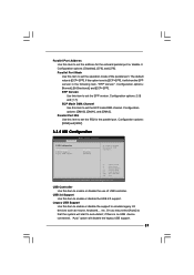
... or disable the support to emulate legacy I/O devices such as mouse, keyboard,... Configuration options: [DMA0], [DMA1], and [DMA3]. Configuration options: [IRQ5] and [IRQ7]. 3.3.8 USB Configuration BIOS SETUP UTILITY Advanced USB Configuration USB Controller USB 2.0 Support Legacy USB Support [Enabled] [Enabled] [Disabled] To enable or disable the onboard USB controllers. +F1 F9...
... or disable the support to emulate legacy I/O devices such as mouse, keyboard,... Configuration options: [DMA0], [DMA1], and [DMA3]. Configuration options: [IRQ5] and [IRQ7]. 3.3.8 USB Configuration BIOS SETUP UTILITY Advanced USB Configuration USB Controller USB 2.0 Support Legacy USB Support [Enabled] [Enabled] [Disabled] To enable or disable the onboard USB controllers. +F1 F9...

User Manual
Page 38
... option as [Enabled], you will be within 2 C. If you install 4-pin CPU fan. The default value is [Disabled]. Configuration options: [Fast], [Middle] and [Slow]. 38 BIOS SETUP UTILITY Main Advanced H/W Monitor Boot Security Exit Hardware Health Event Monitoring CPU Temperature M / B Temperature : 37 C / 98 F : 31 C / 87 F Target Fan Speed Fast Middle Slow...
... option as [Enabled], you will be within 2 C. If you install 4-pin CPU fan. The default value is [Disabled]. Configuration options: [Fast], [Middle] and [Slow]. 38 BIOS SETUP UTILITY Main Advanced H/W Monitor Boot Security Exit Hardware Health Event Monitoring CPU Temperature M / B Temperature : 37 C / 98 F : 31 C / 87 F Target Fan Speed Fast Middle Slow...

User Manual
Page 39
...Help F9 Load Defaults F10 Save and Exit ESC Exit v02.54 (C) Copyright 1985-2005, American Megatrends, Inc. 3.5.1 Boot Settings Configuration BIOS SETUP UTILITY Boot Boot Settings Configuration Boot From Onboard LAN Bootup Num-Lock [Disabled] [On] To enable or disable the boot from ... Item Change Option General Help Load Defaults Save and Exit Exit v02.54 (C) Copyright 1985-2005, American Megatrends, Inc. Main Advanced BIOS SETUP UTILITY H/W Monitor Boot Security Exit Boot Settings Boot Settings Configuration Configure Settings during System Boot. 1st Boot Device 2nd Boot Device ...
...Help F9 Load Defaults F10 Save and Exit ESC Exit v02.54 (C) Copyright 1985-2005, American Megatrends, Inc. 3.5.1 Boot Settings Configuration BIOS SETUP UTILITY Boot Boot Settings Configuration Boot From Onboard LAN Bootup Num-Lock [Disabled] [On] To enable or disable the boot from ... Item Change Option General Help Load Defaults Save and Exit Exit v02.54 (C) Copyright 1985-2005, American Megatrends, Inc. Main Advanced BIOS SETUP UTILITY H/W Monitor Boot Security Exit Boot Settings Boot Settings Configuration Configure Settings during System Boot. 1st Boot Device 2nd Boot Device ...

User Manual
Page 40
Select Screen Select Item Enter Change F1 General Help F9 Load Defaults F10 Save and Exit ESC Exit v02.54 (C) Copyright 1985-2005, American Megatrends, Inc. 40 For the user password, you may also clear it. BIOS SETUP UTILITY Main Advanced H/W Monitor Boot Security Exit Security Settings Supervisor Password : Not Installed User Password : Not Installed Change Supervisor Password Change User Password Install or Change the password. 3.6 Security Screen In this section, you may set or change the supervisor/user password for the system.
Select Screen Select Item Enter Change F1 General Help F9 Load Defaults F10 Save and Exit ESC Exit v02.54 (C) Copyright 1985-2005, American Megatrends, Inc. 40 For the user password, you may also clear it. BIOS SETUP UTILITY Main Advanced H/W Monitor Boot Security Exit Security Settings Supervisor Password : Not Installed User Password : Not Installed Change Supervisor Password Change User Password Install or Change the password. 3.6 Security Screen In this section, you may set or change the supervisor/user password for the system.


