

Intel Smart Response Installation Guide
Page 1
..., and if you want to use RST function, you intend to build RAID 0 or RAID 1 in system at this point! 3. It is not necessary to accelerate AND the SSD in RAID ROM. You MUST ...have both the HDD you just need to set the UEFI option "SATA Mode" to show the newly accelerated system configuration. * Intel® will update the new version RST driver in Icon tray, lower right-hand corner...2. For the new version RST driver, please check our website for the latest information: http://www.asrock.com * Before you use the full SSD as the Cache device, which HDD you wish to Accelerate, if ...
..., and if you want to use RST function, you intend to build RAID 0 or RAID 1 in system at this point! 3. It is not necessary to accelerate AND the SSD in RAID ROM. You MUST ...have both the HDD you just need to set the UEFI option "SATA Mode" to show the newly accelerated system configuration. * Intel® will update the new version RST driver in Icon tray, lower right-hand corner...2. For the new version RST driver, please check our website for the latest information: http://www.asrock.com * Before you use the full SSD as the Cache device, which HDD you wish to Accelerate, if ...
Intel Smart Response Installation Guide
Page 2
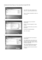
... the SSD broken up as a Cache Volume and the spare capacity volume (Yellow) if applicable. Your GUI window will now change to Accelerate. Reboot the system and cache setup is complete. Enabling Intel Smart Response Technology Setup through Start menu. Open RST GUI, either double-click on front panel. 2. Click "OK...
... the SSD broken up as a Cache Volume and the spare capacity volume (Yellow) if applicable. Your GUI window will now change to Accelerate. Reboot the system and cache setup is complete. Enabling Intel Smart Response Technology Setup through Start menu. Open RST GUI, either double-click on front panel. 2. Click "OK...
User Manual
Page 3
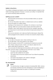
...been damaged as a result of attempting to ensure your safety, it . • Do not spill water or any kind into the system. • The system does not function properly even if you operate your retailer. • The power cord or plug is damaged. • The...all instructions in environments with the product, unplug the power cord and contact a qualified service technician or your system. • Do not use this product in the documentation before cleaning the system. • If you encounter the following technical problems with ambient temperatures between 0o C and 40o C. &#...
...been damaged as a result of attempting to ensure your safety, it . • Do not spill water or any kind into the system. • The system does not function properly even if you operate your retailer. • The power cord or plug is damaged. • The...all instructions in environments with the product, unplug the power cord and contact a qualified service technician or your system. • Do not use this product in the documentation before cleaning the system. • If you encounter the following technical problems with ambient temperatures between 0o C and 40o C. &#...

User Manual
Page 4
... in any way. 4 For your safety, have the optical drive serviced only by the manufacturer. Danger of electronic products. Installation Notices Do not place this system contains a CLASS 1 LASER PRODUCT. Safety cautions and warnings Optical Drive Safety Information Optical drives sold with optical instruments. Do not use or expose this product...
... in any way. 4 For your safety, have the optical drive serviced only by the manufacturer. Danger of electronic products. Installation Notices Do not place this system contains a CLASS 1 LASER PRODUCT. Safety cautions and warnings Optical Drive Safety Information Optical drives sold with optical instruments. Do not use or expose this product...

User Manual
Page 5
... Components 9 1.4 Rear Panel Connections 11 1.5 System Chassis 12 1.6 Remote Controller 13 2 Opening the chassis 14 3 Reinstalling the ODD/HDD 15 4 Installing the second HDD 16 5 Reinstalling the DIMMs 18 6 Reinstalling the CPU 19 7 Driver Installation 20 8 UTILITY MEMU 21 8.1 Instant Boot 21 8.1.1 Introduction 21 8.1.2 Installation 22 8.2 ASRock Extreme Tuning Utility (AXTU 25...
... Components 9 1.4 Rear Panel Connections 11 1.5 System Chassis 12 1.6 Remote Controller 13 2 Opening the chassis 14 3 Reinstalling the ODD/HDD 15 4 Installing the second HDD 16 5 Reinstalling the DIMMs 18 6 Reinstalling the CPU 19 7 Driver Installation 20 8 UTILITY MEMU 21 8.1 Instant Boot 21 8.1.1 Introduction 21 8.1.2 Installation 22 8.2 ASRock Extreme Tuning Utility (AXTU 25...

User Manual
Page 6
... 9.4.9 USB Configuration 52 9.5 Hardware Health Event Monitoring Screen 53 9.6 Boot Screen 54 9.7 Security Screen 55 9.8 Exit Screen 56 10 Software Support 57 10.1 Install Operating System 57 10.2 Support CD Information 57 10.2.1 Running Support CD 57 10.2.2 Drivers Menu 57 10.2.3 Utilities Menu 57 10.2.4 Contact Information 57 6
... 9.4.9 USB Configuration 52 9.5 Hardware Health Event Monitoring Screen 53 9.6 Boot Screen 54 9.7 Security Screen 55 9.8 Exit Screen 56 10 Software Support 57 10.1 Install Operating System 57 10.2 Support CD Information 57 10.2.1 Running Support CD 57 10.2.2 Drivers Menu 57 10.2.3 Utilities Menu 57 10.2.4 Contact Information 57 6
User Manual
Page 8
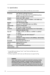
...*1 maximum up to 16GB Intel® HD Graphics 4000 Supports 2.5" SATA HDD (Up to the components and devices of your system. 1.2 Specifications * For barebone systems, CPU, memory, HDDs and ODDs may affect your system stability, or even cause damage to two HDD's) mSATA SSD Supports mSATA SSD ODD BD Combo or DVD Super Multi...
...*1 maximum up to 16GB Intel® HD Graphics 4000 Supports 2.5" SATA HDD (Up to the components and devices of your system. 1.2 Specifications * For barebone systems, CPU, memory, HDDs and ODDs may affect your system stability, or even cause damage to two HDD's) mSATA SSD Supports mSATA SSD ODD BD Combo or DVD Super Multi...

User Manual
Page 9
SATA connector: For ODD SATA data cable 5. HM77 PCH chipset 8. CPU 11. mSATA slot 9 Fan connector 7. Clear CMOS jumper 12. SATA power cable connector (+5V/+12V) for slim ODD & 2.5" HDD 4. ATX5V output power connector for second HDD 6. Memory socket 9. 1.3 System Motherboard Components 1. SATA 3.0 connector: For HDD SATA data cables 2. Infrared module header 10. SATA 3.0 connector: For HDD SATA data cables 3. Mini-PCI Express expansion slot: For WiFi module 13.
SATA connector: For ODD SATA data cable 5. HM77 PCH chipset 8. CPU 11. mSATA slot 9 Fan connector 7. Clear CMOS jumper 12. SATA power cable connector (+5V/+12V) for slim ODD & 2.5" HDD 4. ATX5V output power connector for second HDD 6. Memory socket 9. 1.3 System Motherboard Components 1. SATA 3.0 connector: For HDD SATA data cables 2. Infrared module header 10. SATA 3.0 connector: For HDD SATA data cables 3. Mini-PCI Express expansion slot: For WiFi module 13.

User Manual
Page 12
USB3.0 ports: USB devices 30. 4-in Optical Disc Drive 12 Power ON/OFF button with status indicator 32. Slot-in -1 Card reader (MMC/SD3.0/MS/MS Pro) 31. Microphone 29. 1.5 System Chassis 27. Headphone 28.
USB3.0 ports: USB devices 30. 4-in Optical Disc Drive 12 Power ON/OFF button with status indicator 32. Slot-in -1 Card reader (MMC/SD3.0/MS/MS Pro) 31. Microphone 29. 1.5 System Chassis 27. Headphone 28.

User Manual
Page 13
This product is designed to use these functions. 1.6 Remote Controller Some remote controller functions listed above are only available with the system, you adopt are not allowed to meet MCE standards. 13 If the hardware equipments you are not compatible with the relative hardware equipments.
This product is designed to use these functions. 1.6 Remote Controller Some remote controller functions listed above are only available with the system, you adopt are not allowed to meet MCE standards. 13 If the hardware equipments you are not compatible with the relative hardware equipments.

User Manual
Page 19
Rotate the screw on the top of the CPU fan. 2. Unscrew the screws of the CPU socket. 3. Now you can reinstall a new CPU to the system. 19 Chapter 6 Reinstalling the CPU 1.
Rotate the screw on the top of the CPU fan. 2. Unscrew the screws of the CPU socket. 3. Now you can reinstall a new CPU to the system. 19 Chapter 6 Reinstalling the CPU 1.
User Manual
Page 20
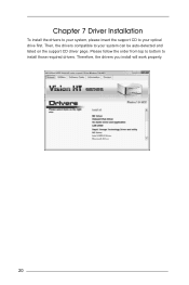
Therefore, the drivers you install will work properly. 20 Then, the drivers compatible to install those required drivers. Please follow the order from top to bottom to your optical drive first. Chapter 7 Driver Installation To install the drivers to your system, please insert the support CD to your system can be auto-detected and listed on the support CD driver page.
Therefore, the drivers you install will work properly. 20 Then, the drivers compatible to install those required drivers. Please follow the order from top to bottom to your optical drive first. Chapter 7 Driver Installation To install the drivers to your system, please insert the support CD to your system can be auto-detected and listed on the support CD driver page.

User Manual
Page 21
... applicable ONLY to individuals that allows you to enter your Windows® desktop in Windows® to save energy, time, money, and improves the system's running speed *. Even the Regular Mode is 3 times faster than the traditional boot time (50 to 60 seconds). Chapter 8 Utility Menu The... software that this product supports. 8.1 Instant Boot 8.1.1 Introduction Instant Boot, a user-friendly tool that do not secure ID and Password to their systems. * The boot time depends on your data safe even when the power is 10 times faster than the traditional boot time. Instant Boot leverages...
... applicable ONLY to individuals that allows you to enter your Windows® desktop in Windows® to save energy, time, money, and improves the system's running speed *. Even the Regular Mode is 3 times faster than the traditional boot time (50 to 60 seconds). Chapter 8 Utility Menu The... software that this product supports. 8.1 Instant Boot 8.1.1 Introduction Instant Boot, a user-friendly tool that do not secure ID and Password to their systems. * The boot time depends on your data safe even when the power is 10 times faster than the traditional boot time. Instant Boot leverages...

User Manual
Page 24
G. After entering into the OS the system will restart automatically. H. The system will shutdown again. Next time when you turn on your system, you can enjoy Instant Boot. 24
G. After entering into the OS the system will restart automatically. H. The system will shutdown again. Next time when you turn on your system, you can enjoy Instant Boot. 24
User Manual
Page 25
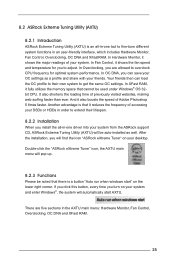
...OC DNA and XFast RAM. 25 After the installation, you turn on your system and enter Windows®, the system will be auto-installed as a profile and share with your system. 8.2 ASRock Extreme Tuning Utility (AXTU) 8.2.1 Introduction ASRock Extreme Tuning Utility (AXTU) is an all -in-one tool to adjust..... It also shortens the loading time of your friends. In Hardware Monitor, it also boosts the speed of accessing your system from the ASRock support CD, ASRock Extreme Tuning Utility (AXTU) will automatically start " on your OC settings as well. And it shows the major readings ...
...OC DNA and XFast RAM. 25 After the installation, you turn on your system and enter Windows®, the system will be auto-installed as a profile and share with your system. 8.2 ASRock Extreme Tuning Utility (AXTU) 8.2.1 Introduction ASRock Extreme Tuning Utility (AXTU) is an all -in-one tool to adjust..... It also shortens the loading time of your friends. In Hardware Monitor, it also boosts the speed of accessing your system from the ASRock support CD, ASRock Extreme Tuning Utility (AXTU) will automatically start " on your OC settings as well. And it shows the major readings ...

User Manual
Page 26
Fan Control In the Fan Control section, there are CPU speed and CPU ratio. In Temperature, it shows the major readings of your system's temperature. Hardware Monitor In the Hardware Monitor section, it shows the major readings of CPU and motherboard temperatures. In Clock, there are...any abnormal situations occuring to adjust the settings by clicking the "+/-" and confirm by "APPLY" afterwards. 26 In Voltage, there are able to your system. The main readings include Clock, Fan & Temperature, and Voltage. In CPU Fan, it shows the fan target speed and temperature, and you are...
Fan Control In the Fan Control section, there are CPU speed and CPU ratio. In Temperature, it shows the major readings of your system's temperature. Hardware Monitor In the Hardware Monitor section, it shows the major readings of CPU and motherboard temperatures. In Clock, there are...any abnormal situations occuring to adjust the settings by clicking the "+/-" and confirm by "APPLY" afterwards. 26 In Voltage, there are able to your system. The main readings include Clock, Fan & Temperature, and Voltage. In CPU Fan, it shows the fan target speed and temperature, and you are...

User Manual
Page 27
... are Clock and Voltage chapters for possible damages caused by clicking the "+/-" at your OC settings as yours. ASRock is not responsible for parameter settings adjustment in pursuit of overclocking settings. If system hangs after overclocking, please remove the AC power cord and plug the AC power cord again before you to...
... are Clock and Voltage chapters for possible damages caused by clicking the "+/-" at your OC settings as yours. ASRock is not responsible for parameter settings adjustment in pursuit of overclocking settings. If system hangs after overclocking, please remove the AC power cord and plug the AC power cord again before you to...
User Manual
Page 33
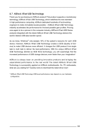
...new standard in the computer industry, ASRock XFast USB Series products integrated with the latest ASRock XFast USB Technology delivers the world's fastest USB data transfer speed. The latest ASRock XFast USB Technology is always keen on ASRock motherboards. ASRock dedicated hundreds of Service) to be ... assigns 10% of USB storage devices, even faster than your hardware configuration. 33 With the unique ASRock XFast USB Technology (Similar as HDD NCQ technology), you will surprisingly find the increased performance of the system's resource for the best possible gain profiles.
...new standard in the computer industry, ASRock XFast USB Series products integrated with the latest ASRock XFast USB Technology delivers the world's fastest USB data transfer speed. The latest ASRock XFast USB Technology is always keen on ASRock motherboards. ASRock dedicated hundreds of Service) to be ... assigns 10% of USB storage devices, even faster than your hardware configuration. 33 With the unique ASRock XFast USB Technology (Similar as HDD NCQ technology), you will surprisingly find the increased performance of the system's resource for the best possible gain profiles.

User Manual
Page 34
... the all-in-one driver to your desktop. When you install ASRock XFast USB Technology. Please unplug your system successfully. You can find the icon "XFast USB" on the ...You will see the message below carefully before you plug an USB device to your system from ASRock's support CD. C. After ASRock XFast USB driver is installed to your USB device and plug it on your ...computer for the first time. You will find it to get the latest utility: http://www.asrock.com/Feature/XFastUSB/index.asp B. This message will be auto-installed as well. Please read the ...
... the all-in-one driver to your desktop. When you install ASRock XFast USB Technology. Please unplug your system successfully. You can find the icon "XFast USB" on the ...You will see the message below carefully before you plug an USB device to your system from ASRock's support CD. C. After ASRock XFast USB driver is installed to your USB device and plug it on your ...computer for the first time. You will find it to get the latest utility: http://www.asrock.com/Feature/XFastUSB/index.asp B. This message will be auto-installed as well. Please read the ...
User Manual
Page 37
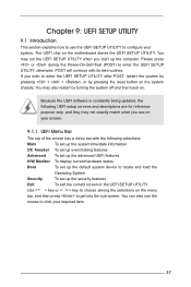
... Exit To exit the current screen or the UEFI SETUP UTILITY Use < > key or < > key to choose among the selections on the system chassis. Chapter 9: UEFI SETUP UTILITY 9.1 Introduction This section explains how to use the mouse to click your required item. 37 Please press or ... a menu bar with its test routines. Because the UEFI software is constantly being updated, the following selections: Main To set up the system time/date information OC Tweaker To set up overclocking features Advanced To set up the advanced UEFI features H/W Monitor To display current hardware status...
... Exit To exit the current screen or the UEFI SETUP UTILITY Use < > key or < > key to choose among the selections on the system chassis. Chapter 9: UEFI SETUP UTILITY 9.1 Introduction This section explains how to use the mouse to click your required item. 37 Please press or ... a menu bar with its test routines. Because the UEFI software is constantly being updated, the following selections: Main To set up the system time/date information OC Tweaker To set up overclocking features Advanced To set up the advanced UEFI features H/W Monitor To display current hardware status...
