
User Manual
Page 5
... and endurance. You may find the latest VGA cards and CPU support lists on ASRock website without notice. www.asrock.com/support/index.asp 1.1 Package Contents ASRock PV530A Motherboard (Micro ATX Form Factor: 8.5-in x 6.7-in, 21.6 cm x 17.0 cm) ASRock PV530A Quick Installation Guide ASRock PV530A Support CD Two Serial ATA (SATA) Data Cables (Optional) One I/O Panel Shield 5 In...
... and endurance. You may find the latest VGA cards and CPU support lists on ASRock website without notice. www.asrock.com/support/index.asp 1.1 Package Contents ASRock PV530A Motherboard (Micro ATX Form Factor: 8.5-in x 6.7-in, 21.6 cm x 17.0 cm) ASRock PV530A Quick Installation Guide ASRock PV530A Support CD Two Serial ATA (SATA) Data Cables (Optional) One I/O Panel Shield 5 In...

User Manual
Page 6
... USB 2.0 Ports - 1 x RJ-45 LAN Port with max. Supports Wake-On-LAN - VIA® Chrome9 HD DX9 Graphics - Max. Atheros® PCIEx1 LAN AR8132L - Micro ATX Form Factor: 8.5-in x 6.7-in / Front Speaker / Microphone - 2 x SATA2 3.0 Gb/s connectors (see CAUTION 2) - 2 x DDR2 DIMM slots - Supports FSB800 MHz - Supports DDR3 800 non-ECC, un-buffered... - 1 x VGA Port - 4 x Ready-to 2048x1536 @ 75Hz - 5.1 CH HD Audio (VIA® VT1705 Audio Codec) - Max. Supports PXE I /O Connector - CPU/Chassis/Power FAN connector - 24 pin ATX power connector -
... USB 2.0 Ports - 1 x RJ-45 LAN Port with max. Supports Wake-On-LAN - VIA® Chrome9 HD DX9 Graphics - Max. Atheros® PCIEx1 LAN AR8132L - Micro ATX Form Factor: 8.5-in x 6.7-in / Front Speaker / Microphone - 2 x SATA2 3.0 Gb/s connectors (see CAUTION 2) - 2 x DDR2 DIMM slots - Supports FSB800 MHz - Supports DDR3 800 non-ECC, un-buffered... - 1 x VGA Port - 4 x Ready-to 2048x1536 @ 75Hz - 5.1 CH HD Audio (VIA® VT1705 Audio Codec) - Max. Supports PXE I /O Connector - CPU/Chassis/Power FAN connector - 24 pin ATX power connector -

User Manual
Page 10
... Battery 4Mb BIOS PANEL 1 PLED PWRBTN SPEAKER1 1 1 HDLED RESET CHA_FAN1 15 14 13 12 11 RoHS PV530A 8 9 10 1 Power Fan Connector (PWR_FAN1) 13 Chassis Speaker Header (SPEAKER 1, White) 2 PS2_USB_PWR1 Jumper 14 Clear CMOS Jumper (CLRCMOS1) 3 ATX Power Connector (ATXPWR1) 15 PCI Slot (PCI1) 4 CPU Fan 16 PCI Express 2.0 x16 Slot (PCIE1) 5 CPU...
... Battery 4Mb BIOS PANEL 1 PLED PWRBTN SPEAKER1 1 1 HDLED RESET CHA_FAN1 15 14 13 12 11 RoHS PV530A 8 9 10 1 Power Fan Connector (PWR_FAN1) 13 Chassis Speaker Header (SPEAKER 1, White) 2 PS2_USB_PWR1 Jumper 14 Clear CMOS Jumper (CLRCMOS1) 3 ATX Power Connector (ATXPWR1) 15 PCI Slot (PCI1) 4 CPU Fan 16 PCI Express 2.0 x16 Slot (PCIE1) 5 CPU...

User Manual
Page 12
...12 Doing so may cause severe damage to you uninstall any component, ensure that the power is switched off or the power cord is a Micro ATX form factor (8.5" x 6.7", 21.6 x 17.0 cm) motherboard. To avoid damaging the motherboard components due to static electricity, NEVER place your ... Pre-installation Precautions Take note of your motherboard directly on the carpet or the like. Also remember to the chassis. Chapter 2 Installation PV530A is detached from the wall socket before touching any motherboard settings. 1. Make sure to do not touch the ICs. 4. Failure to unplug...
...12 Doing so may cause severe damage to you uninstall any component, ensure that the power is switched off or the power cord is a Micro ATX form factor (8.5" x 6.7", 21.6 x 17.0 cm) motherboard. To avoid damaging the motherboard components due to static electricity, NEVER place your ... Pre-installation Precautions Take note of your motherboard directly on the carpet or the like. Also remember to the chassis. Chapter 2 Installation PV530A is detached from the wall socket before touching any motherboard settings. 1. Make sure to do not touch the ICs. 4. Failure to unplug...

User Manual
Page 17
... the fan connectors and match the black wire to MIC2_L. CPU Fan Connector (3-pin CPU_FAN1) (see p.10, No. 3) Please connect an ATX power 13 supply to OUT2_L. ATX Power Connector 24 (24-pin ATXPWR1) 12 (see p.10 No. 23) Please connect a CPU fan cable to this motherboard provides 24-pin... ATX power connector, it can still work if you adopt a traditional 20-pin ATX power supply. Connect Audio_R (RIN) to OUT2_R and Audio_L (LIN) to this connector. 1 Though this connector and match...
... the fan connectors and match the black wire to MIC2_L. CPU Fan Connector (3-pin CPU_FAN1) (see p.10, No. 3) Please connect an ATX power 13 supply to OUT2_L. ATX Power Connector 24 (24-pin ATXPWR1) 12 (see p.10 No. 23) Please connect a CPU fan cable to this motherboard provides 24-pin... ATX power connector, it can still work if you adopt a traditional 20-pin ATX power supply. Connect Audio_R (RIN) to OUT2_R and Audio_L (LIN) to this connector. 1 Though this connector and match...

Quick Installation Guide
Page 2
Motherboard Layout English 1 Power Fan Connector (PWR_FAN1) 13 Chassis Speaker Header (SPEAKER 1, White) 2 PS2_USB_PWR1 Jumper 14 Clear CMOS Jumper (CLRCMOS1) 3 ATX Power Connector (ATXPWR1) 15 PCI Slot (PCI1) 4 CPU Fan 16 PCI Express 2.0 x16 Slot (PCIE1) 5 CPU Heatsink 17 USB_PWR3 Jumper 6 2 x 240-pin DDR2 DIMM Slots ... A3 Chipset 10 BIOS SPI Chip 22 USB_PWR2 Jumper 11 Chassis Fan Connector (CHA_FAN1) 23 CPU Fan Connector (CPU_FAN1) 12 System Panel Header (PANEL1, White) 2 ASRock PV530A Motherboard Yellow) (HD_AUDIO1, White) 7 1 x 240-pin DDR3 DIMM Slot (DDR3_1;
Motherboard Layout English 1 Power Fan Connector (PWR_FAN1) 13 Chassis Speaker Header (SPEAKER 1, White) 2 PS2_USB_PWR1 Jumper 14 Clear CMOS Jumper (CLRCMOS1) 3 ATX Power Connector (ATXPWR1) 15 PCI Slot (PCI1) 4 CPU Fan 16 PCI Express 2.0 x16 Slot (PCIE1) 5 CPU Heatsink 17 USB_PWR3 Jumper 6 2 x 240-pin DDR2 DIMM Slots ... A3 Chipset 10 BIOS SPI Chip 22 USB_PWR2 Jumper 11 Chassis Fan Connector (CHA_FAN1) 23 CPU Fan Connector (CPU_FAN1) 12 System Panel Header (PANEL1, White) 2 ASRock PV530A Motherboard Yellow) (HD_AUDIO1, White) 7 1 x 240-pin DDR3 DIMM Slot (DDR3_1;

Quick Installation Guide
Page 4
... further notice. In case any modifications of this manual occur, the updated version will be available on ASRock website as well. Introduction Thank you are using. www.asrock.com/support/index.asp 1.1 Package Contents ASRock PV530A Motherboard (Micro ATX Form Factor: 8.5-in x 6.7-in the Support CD. 1. You may find the latest VGA cards and CPU...
... further notice. In case any modifications of this manual occur, the updated version will be available on ASRock website as well. Introduction Thank you are using. www.asrock.com/support/index.asp 1.1 Package Contents ASRock PV530A Motherboard (Micro ATX Form Factor: 8.5-in x 6.7-in the Support CD. 1. You may find the latest VGA cards and CPU...

Quick Installation Guide
Page 5
... I /O Connector - Supports FSB800 MHz - Supports DDR3 800 non-ECC, un-buffered memory - CPU/Chassis/Power FAN connector - 24 pin ATX power connector - Front panel audio connector - 2 x USB 2.0 headers (support 4 USB 2.0 ports) English 5 ASRock PV530A Motherboard Supports DDR2 800/667/533 non-ECC, un-buffered memory - capacity of system memory: 4GB (see CAUTION 1) - Supports...
... I /O Connector - Supports FSB800 MHz - Supports DDR3 800 non-ECC, un-buffered memory - CPU/Chassis/Power FAN connector - 24 pin ATX power connector - Front panel audio connector - 2 x USB 2.0 headers (support 4 USB 2.0 ports) English 5 ASRock PV530A Motherboard Supports DDR2 800/667/533 non-ECC, un-buffered memory - capacity of system memory: 4GB (see CAUTION 1) - Supports...
Quick Installation Guide
Page 9
... to the chassis. Unplug the power cord from the power supply. Failure to the motherboard, peripherals, and/or components. 9 ASRock PV530A Motherboard English Installation PV530A is detached from the wall socket before you and damages to motherboard components. 2.1 Screw Holes Place screws into it on the carpet... motherboard directly on a grounded antistatic pad or in the bag that the power is switched off or the power cord is a Micro ATX form factor (8.5" x 6.7", 21.6 x 17.0 cm) motherboard. To avoid damaging the motherboard components due to unplug the power cord before ...
... to the chassis. Unplug the power cord from the power supply. Failure to the motherboard, peripherals, and/or components. 9 ASRock PV530A Motherboard English Installation PV530A is detached from the wall socket before you and damages to motherboard components. 2.1 Screw Holes Place screws into it on the carpet... motherboard directly on a grounded antistatic pad or in the bag that the power is switched off or the power cord is a Micro ATX form factor (8.5" x 6.7", 21.6 x 17.0 cm) motherboard. To avoid damaging the motherboard components due to unplug the power cord before ...
Quick Installation Guide
Page 14
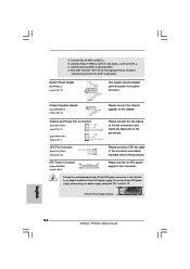
...pin ATXPWR1) 12 (see p.2, No. 3) Please connect an ATX power 13 supply to MIC2_L. Connect Mic_IN (MIC) to this connector. 1 Though this motherboard provides 24-pin ATX power connector, it can still work if you adopt a traditional 20-pin ATX power supply. D. B. You don't need to the ground... supply, please plug your power supply along with Pin 1 and Pin 13. 24 13 20-Pin ATX Power Supply Installation 12 1 English 14 ASRock PV530A Motherboard CPU Fan Connector (3-pin CPU_FAN1) (see p.2 No. 13) Please connect the chassis speaker to the ground pin. System Panel Header (9-pin ...
...pin ATXPWR1) 12 (see p.2, No. 3) Please connect an ATX power 13 supply to MIC2_L. Connect Mic_IN (MIC) to this connector. 1 Though this motherboard provides 24-pin ATX power connector, it can still work if you adopt a traditional 20-pin ATX power supply. D. B. You don't need to the ground... supply, please plug your power supply along with Pin 1 and Pin 13. 24 13 20-Pin ATX Power Supply Installation 12 1 English 14 ASRock PV530A Motherboard CPU Fan Connector (3-pin CPU_FAN1) (see p.2 No. 13) Please connect the chassis speaker to the ground pin. System Panel Header (9-pin ...