
Intel Rapid Storage Guide
Page 12
... Enter. 4. When finished press Enter. 12 Click F2 or Delete to select the drive. Enable RAID in System BIOS Use the instructions included with your motherboard to enable RAID in the system BIOS, a RAID volume must be created, and the F6 installation method must be enabled in the system BIOS. 1. How...
... Enter. 4. When finished press Enter. 12 Click F2 or Delete to select the drive. Enable RAID in System BIOS Use the instructions included with your motherboard to enable RAID in the system BIOS, a RAID volume must be created, and the F6 installation method must be enabled in the system BIOS. 1. How...

User Manual
Page 2
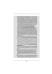
..., USA ONLY The Lithium battery adopted on this manual. "Perchlorate Material-special handling may not be constructed as a commitment by ASRock. When you discard the Lithium battery in California, USA, please follow the related regulations in this manual may or may apply...owners' benefit, without intent to change without written consent of ASRock Inc. Copyright Notice: No part of this device must accept any interference received, including interference that may appear in this motherboard contains Perchlorate, a toxic substance controlled in Perchlorate Best Management Practices ...
..., USA ONLY The Lithium battery adopted on this manual. "Perchlorate Material-special handling may not be constructed as a commitment by ASRock. When you discard the Lithium battery in California, USA, please follow the related regulations in this manual may or may apply...owners' benefit, without intent to change without written consent of ASRock Inc. Copyright Notice: No part of this device must accept any interference received, including interference that may appear in this motherboard contains Perchlorate, a toxic substance controlled in Perchlorate Best Management Practices ...

User Manual
Page 3
Contents 1 Introduction 5 1.1 Package Contents 5 1.2 Specifications 6 1.3 Motherboard Layout 12 1.4 I/O Panel 13 2 Installation 15 2.1 Screw Holes 15 2.2 Pre-installation Precautions 15 2.3 CPU Installation 16 2.4 Installation of Heatsink and CPU fan 18 2.5 Installation of ...
Contents 1 Introduction 5 1.1 Package Contents 5 1.2 Specifications 6 1.3 Motherboard Layout 12 1.4 I/O Panel 13 2 Installation 15 2.1 Screw Holes 15 2.2 Pre-installation Precautions 15 2.3 CPU Installation 16 2.4 Installation of Heatsink and CPU fan 18 2.5 Installation of ...

User Manual
Page 5
...64257;nd the latest VGA cards and CPU support lists on ASRock website without notice. ASRock website http://www.asrock.com If you are using. www.asrock.com/support/index.asp 1.1 Package Contents ASRock P67 Pro3 Motherboard (ATX Form Factor: 12.0-in x 9.6-in our support ...subject to the hardware installation. In this manual, chapter 1 and 2 contain introduction of this motherboard, please visit our website for purchasing ASRock P67 Pro3 motherboard, a reliable motherboard produced under ASRock's consistently stringent quality control. To get better performance in Windows® 7 / 7 64-...
...64257;nd the latest VGA cards and CPU support lists on ASRock website without notice. ASRock website http://www.asrock.com If you are using. www.asrock.com/support/index.asp 1.1 Package Contents ASRock P67 Pro3 Motherboard (ATX Form Factor: 12.0-in x 9.6-in our support ...subject to the hardware installation. In this manual, chapter 1 and 2 contain introduction of this motherboard, please visit our website for purchasing ASRock P67 Pro3 motherboard, a reliable motherboard produced under ASRock's consistently stringent quality control. To get better performance in Windows® 7 / 7 64-...

User Manual
Page 9
...memory size may depend on page 19 for system usage under Windows® 7 / VistaTM / XP. For audio output, this motherboard supports both stereo and mono modes. Due to get the same OC settings. Please check the table on page 13 for you ... clicks without sacrificing computing performance. In Hardware Monitor, it shows the fan speed and temperature for proper connection. 6. ASRock website: http://www.asrock.com 7. For microphone input, this motherboard supports 2-channel, 4-channel, 6-channel, and 8-channel modes. Before you implement Dual Channel Memory Technology, make sure ...
...memory size may depend on page 19 for system usage under Windows® 7 / VistaTM / XP. For audio output, this motherboard supports both stereo and mono modes. Due to get the same OC settings. Please check the table on page 13 for you ... clicks without sacrificing computing performance. In Hardware Monitor, it shows the fan speed and temperature for proper connection. 6. ASRock website: http://www.asrock.com 7. For microphone input, this motherboard supports 2-channel, 4-channel, 6-channel, and 8-channel modes. Before you implement Dual Channel Memory Technology, make sure ...
User Manual
Page 10
...Windows® 7 / 7 64 bit / VistaTM / VistaTM 64 bit, and your browser version is not recommended to ASRock of charging your iPhone/iPod touch. Although this motherboard offers stepless control, it makes your iPhone charged much quickly from App store to your Apple devices, such as a game... than before. Frequencies other than the recommended CPU bus frequencies may cause the instability of ficial website or ASRock software support CD to your motherboard, and also download the free AIWI Lite from your PC enters into an enhanced view for you the most visited...
...Windows® 7 / 7 64 bit / VistaTM / VistaTM 64 bit, and your browser version is not recommended to ASRock of charging your iPhone/iPod touch. Although this motherboard offers stepless control, it makes your iPhone charged much quickly from App store to your Apple devices, such as a game... than before. Frequencies other than the recommended CPU bus frequencies may cause the instability of ficial website or ASRock software support CD to your motherboard, and also download the free AIWI Lite from your PC enters into an enhanced view for you the most visited...

User Manual
Page 11
... for Energy Using Product, was a provision regulated by European Union to Intel's suggestion, the EuP ready power supply must meet EuP standard, an EuP ready motherboard and an EuP ready power supply are required.
... for Energy Using Product, was a provision regulated by European Union to Intel's suggestion, the EuP ready power supply must meet EuP standard, an EuP ready motherboard and an EuP ready power supply are required.

User Manual
Page 12
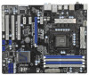
1.3 Motherboard Layout 1 2 34 24.4cm (9.6 in) ATX12V1 CPU_FAN2 CPU_FAN1 PS2 Mouse 5 ...PWR_FAN1 CHA_FAN3 REAR SPK FRONT Bottom: CTR BASS Top: LINE IN Center: Bottom: MIC IN 38 37 PCIE1 P67 Pro3 RoHS 36 PCIE2 ErP/EuP Ready PCI Express 2.0 Designed in Taipei 35 PCIE3 CMOS 34 Battery Super I/O PCIE4... 1 CLRCMOS1 33 AUDIO CODEC PCI1 USB 3.0 PCI2 USB8_9 CHA_FAN2 SATA3 6Gb/s Intel P67 64Mb BIOS PLED1 1 SPEAKER1 1 PANEL1 PLED PWRBTN 1 HDLED RESET SATA3_1 SATA3_0 SATA2_3 SATA2_2 32 HD_AUDIO1 1 HDMI_SPDIF1 COM1 1 1...
1.3 Motherboard Layout 1 2 34 24.4cm (9.6 in) ATX12V1 CPU_FAN2 CPU_FAN1 PS2 Mouse 5 ...PWR_FAN1 CHA_FAN3 REAR SPK FRONT Bottom: CTR BASS Top: LINE IN Center: Bottom: MIC IN 38 37 PCIE1 P67 Pro3 RoHS 36 PCIE2 ErP/EuP Ready PCI Express 2.0 Designed in Taipei 35 PCIE3 CMOS 34 Battery Super I/O PCIE4... 1 CLRCMOS1 33 AUDIO CODEC PCI1 USB 3.0 PCI2 USB8_9 CHA_FAN2 SATA3 6Gb/s Intel P67 64Mb BIOS PLED1 1 SPEAKER1 1 PANEL1 PLED PWRBTN 1 HDLED RESET SATA3_1 SATA3_0 SATA2_3 SATA2_2 32 HD_AUDIO1 1 HDMI_SPDIF1 COM1 1 1...

User Manual
Page 15
...ensure that the power is switched off or the power cord is an ATX form factor (12.0" x 9.6", 30.5 x 24.4 cm) motherboard. Whenever you uninstall any motherboard settings. 1. Unplug the power cord from the power supply. Failure to do so may cause physical injuries to you and damages to unplug...and do so may cause severe damage to static electricity, NEVER place your chassis to the chassis. Hold components by circles to secure the motherboard to ensure that comes with the component. Failure to do not touch the ICs. 4. Chapter 2: Installation This is detached from the wall...
...ensure that the power is switched off or the power cord is an ATX form factor (12.0" x 9.6", 30.5 x 24.4 cm) motherboard. Whenever you uninstall any motherboard settings. 1. Unplug the power cord from the power supply. Failure to do so may cause physical injuries to you and damages to unplug...and do so may cause severe damage to static electricity, NEVER place your chassis to the chassis. Hold components by circles to secure the motherboard to ensure that comes with the component. Failure to do not touch the ICs. 4. Chapter 2: Installation This is detached from the wall...
User Manual
Page 16
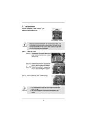
... the socket: Step 1-1. Step 1-3. Step 2. Do not force to fully open position at approximately 135 degrees. Otherwise, the CPU will be placed if returning the motherboard for after service. 16 Rotate the load plate to fully open position at approximately 100 degrees. Load Plate Load Lever Contact Array Socket Body 1155...
... the socket: Step 1-1. Step 1-3. Step 2. Do not force to fully open position at approximately 135 degrees. Otherwise, the CPU will be placed if returning the motherboard for after service. 16 Rotate the load plate to fully open position at approximately 100 degrees. Load Plate Load Lever Contact Array Socket Body 1155...

User Manual
Page 18
...Align fasteners with each other components. Ensure that the CPU and the heatsink are securely fastened and in good contact with the motherboard throughholes. Below is equipped with remaining fasteners. Apply Thermal Interface Material Step 2. Secure excess cable with tie-wrap to ensure cable... throughholes are oriented on side closest to the CPU fan connector on the socket surface. Repeat with 1155-Pin socket that this motherboard supports Combo Cooler Option (C.C.O.), which provides the flexible option to adopt three different CPU cooler types, Socket LGA 775, ...
...Align fasteners with each other components. Ensure that the CPU and the heatsink are securely fastened and in good contact with the motherboard throughholes. Below is equipped with remaining fasteners. Apply Thermal Interface Material Step 2. Secure excess cable with tie-wrap to ensure cable... throughholes are oriented on side closest to the CPU fan connector on the socket surface. Repeat with 1155-Pin socket that this motherboard supports Combo Cooler Option (C.C.O.), which provides the flexible option to adopt three different CPU cooler types, Socket LGA 775, ...

User Manual
Page 19
...If you always need to install identical (the same brand, speed, size and chip-type) DDR3 DIMM pair in the DDR3 DIMM slots on this motherboard. 19 2.5 Installation of the same color. Dual Channel Memory Configurations DDR3_A1 DDR3_A2 DDR3_B1 DDR3_B2 (Blue Slot) (White Slot) (Blue Slot) ...slots (DDR3_A1 and DDR3_B1), or in all four slots. It is unable to install them in Dual Channel A (DDR3_ A1 and DDR3_B1; This motherboard also allows you have to install a DDR or DDR2 memory module into DDR3 slot; Populated (3)* Populated Populated Populated Populated * For the con&#...
...If you always need to install identical (the same brand, speed, size and chip-type) DDR3 DIMM pair in the DDR3 DIMM slots on this motherboard. 19 2.5 Installation of the same color. Dual Channel Memory Configurations DDR3_A1 DDR3_A2 DDR3_B1 DDR3_B2 (Blue Slot) (White Slot) (Blue Slot) ...slots (DDR3_A1 and DDR3_B1), or in all four slots. It is unable to install them in Dual Channel A (DDR3_ A1 and DDR3_B1; This motherboard also allows you have to install a DDR or DDR2 memory module into DDR3 slot; Populated (3)* Populated Populated Populated Populated * For the con&#...

User Manual
Page 20
... 2. Align a DIMM on the slot such that the notch on the DIMM matches the break on the slot. Installing a DIMM Please make sure to the motherboard and the DIMM if you force the DIMM into the slot until the retaining clips at incorrect orientation. notch break notch break The DIMM only...
... 2. Align a DIMM on the slot such that the notch on the DIMM matches the break on the slot. Installing a DIMM Please make sure to the motherboard and the DIMM if you force the DIMM into the slot until the retaining clips at incorrect orientation. notch break notch break The DIMM only...

User Manual
Page 21
... expansion card and make sure that the power supply is switched off or the power cord is completely seated on this motherboard. Step 5. Remove the system unit cover (if your motherboard is used for later use . Step 3. Before installing the expansion card, please make necessary hardware settings for PCI Express x16 lane...
... expansion card and make sure that the power supply is switched off or the power cord is completely seated on this motherboard. Step 5. Remove the system unit cover (if your motherboard is used for later use . Step 3. Before installing the expansion card, please make necessary hardware settings for PCI Express x16 lane...

User Manual
Page 23
2.8 Onboard Headers and Connectors Onboard headers and connectors are NOT jumpers. If you install the HDD on the eSATA port on this motherboard. 23 Serial ATAII Connectors (SATA2_2: see p.12, No. 18) (SATA2_3: see p.12, No. 17) (SATA2_4: see p.12, No. 19) (SATA2_5: see p.12, No. 20... (SATA3_0: see p.12, No. 16) (SATA3_1: see p.12 No. 29) the red-striped side to 3.0 Gb/s data transfer rate. Either end of the motherboard! Placing jumper caps over these headers and connectors. The current SATAII interface allows up to the SATA / SATAII / SATA3 hard disk or the SATAII / SATA3...
2.8 Onboard Headers and Connectors Onboard headers and connectors are NOT jumpers. If you install the HDD on the eSATA port on this motherboard. 23 Serial ATAII Connectors (SATA2_2: see p.12, No. 18) (SATA2_3: see p.12, No. 17) (SATA2_4: see p.12, No. 19) (SATA2_5: see p.12, No. 20... (SATA3_0: see p.12, No. 16) (SATA3_1: see p.12 No. 29) the red-striped side to 3.0 Gb/s data transfer rate. Either end of the motherboard! Placing jumper caps over these headers and connectors. The current SATAII interface allows up to the SATA / SATAII / SATA3 hard disk or the SATAII / SATA3...

User Manual
Page 24
... USB_PWR USB_PWR P-13 P+13 GND DUMMY 1 GND P+12 P-12 USB_PWR Besides six default USB 2.0 ports on the I/O panel, there are three USB 2.0 headers on this motherboard. Each USB 2.0 header can support two USB 2.0 ports.
... USB_PWR USB_PWR P-13 P+13 GND DUMMY 1 GND P+12 P-12 USB_PWR Besides six default USB 2.0 ports on the I/O panel, there are three USB 2.0 headers on this motherboard. Each USB 2.0 header can support two USB 2.0 ports.

User Manual
Page 26
... CHA_FAN1) (see p.12 No. 27) FAN_SPEED_CONTROL GND +12V CHA_FAN_SPEED (3-pin CHA_FAN2) (see p.12 No. 12) Please connect the chassis speaker to this motherboard, please connect it to this motherboard provides 4-Pin CPU fan (Quiet Fan) support, the 3-Pin CPU fan still can work successfully even without the fan speed control function. Though...
... CHA_FAN1) (see p.12 No. 27) FAN_SPEED_CONTROL GND +12V CHA_FAN_SPEED (3-pin CHA_FAN2) (see p.12 No. 12) Please connect the chassis speaker to this motherboard, please connect it to this motherboard provides 4-Pin CPU fan (Quiet Fan) support, the 3-Pin CPU fan still can work successfully even without the fan speed control function. Though...

User Manual
Page 27
... Power Connector (24-pin ATXPWR1) (see p.12 No. 7) 12 24 Please connect an ATX power supply to this connector. 1 13 Though this motherboard provides 24-pin ATX power connector, 12 24 it can still work if you adopt a traditional 20-pin ATX power supply. To use the 4-pin... (9-pin COM1) (see p.12 No. 32) 1 GND SPDIFOUT HDMI_SPDIF header, providing SPDIF audio output to HDMI VGA card, allows the system to this motherboard provides 8-pin ATX 12V power connector, it can still work if you adopt a traditional 4-pin ATX 12V power supply. HDMI_SPDIF Header (2-pin HDMI_SPDIF1) (see...
... Power Connector (24-pin ATXPWR1) (see p.12 No. 7) 12 24 Please connect an ATX power supply to this connector. 1 13 Though this motherboard provides 24-pin ATX power connector, 12 24 it can still work if you adopt a traditional 20-pin ATX power supply. To use the 4-pin... (9-pin COM1) (see p.12 No. 32) 1 GND SPDIFOUT HDMI_SPDIF header, providing SPDIF audio output to HDMI VGA card, allows the system to this motherboard provides 8-pin ATX 12V power connector, it can still work if you adopt a traditional 4-pin ATX 12V power supply. HDMI_SPDIF Header (2-pin HDMI_SPDIF1) (see...

User Manual
Page 28
2.9 Smart Switches The motherboard has three smart switches: power switch, reset switch and clear CMOS switch, allowing users to quickly turn on /off the system. Clear CMOS Switch (CLRCBTN) (...
2.9 Smart Switches The motherboard has three smart switches: power switch, reset switch and clear CMOS switch, allowing users to quickly turn on /off the system. Clear CMOS Switch (CLRCBTN) (...

User Manual
Page 34
.../ SATAII hard disks. This section will guide you to the SATA / SATAII hard disk. 2.12 Serial ATA3 (SATA3) Hard Disks Installation This motherboard adopts Intel® P67 chipset that supports Serial ATA (SATA) / Serial ATAII (SATAII) hard disks and RAID (RAID 0, RAID 1, RAID 10, RAID 5 and...hard disks into the drive bays of your chassis. 2.11 Serial ATA (SATA) / Serial ATAII (SATAII) Hard Disks Installation This motherboard adopts Intel® P67 chipset that supports Serial ATA3 (SATA3) hard disks and RAID (RAID 0, RAID 1, RAID 10, RAID 5 and Intel Rapid Storage) functions.
.../ SATAII hard disks. This section will guide you to the SATA / SATAII hard disk. 2.12 Serial ATA3 (SATA3) Hard Disks Installation This motherboard adopts Intel® P67 chipset that supports Serial ATA (SATA) / Serial ATAII (SATAII) hard disks and RAID (RAID 0, RAID 1, RAID 10, RAID 5 and...hard disks into the drive bays of your chassis. 2.11 Serial ATA (SATA) / Serial ATAII (SATAII) Hard Disks Installation This motherboard adopts Intel® P67 chipset that supports Serial ATA3 (SATA3) hard disks and RAID (RAID 0, RAID 1, RAID 10, RAID 5 and Intel Rapid Storage) functions.


