
User Manual
Page 9
ASRock website: http://www.asrock.com/feature/IES/index.html 11...update system BIOS without preparing an additional floppy diskette or other complicated flash utility. ASRock Instant Flash is not recommended to spray thermal grease between the CPU and the ...Featuring an advanced proprietary hardware and software design, Intelligent Energy Saver is able to access ASRock Instant Flash. In other than 50% under the operating system and simplifies the complicated recording...was a provision regulated by ASRock, provides a convenient way for the user to adopt two different CPU cooler types...
ASRock website: http://www.asrock.com/feature/IES/index.html 11...update system BIOS without preparing an additional floppy diskette or other complicated flash utility. ASRock Instant Flash is not recommended to spray thermal grease between the CPU and the ...Featuring an advanced proprietary hardware and software design, Intelligent Energy Saver is able to access ASRock Instant Flash. In other than 50% under the operating system and simplifies the complicated recording...was a provision regulated by ASRock, provides a convenient way for the user to adopt two different CPU cooler types...
User Manual
Page 11
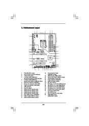
... SATAII_1 SATAII_2 23 22 21 20 1918 17 16 15 14 6 7 8 9 10 11 12 13 1 PS2_USB_PWR1 Jumper 2 ATX 12V Power Connector (ATX12V1) 3 1156-Pin CPU Socket 4 2 x 240-pin DDR3 DIMM Slots (Dual Channel: DDR3_A2, DDR3_B2, Blue) 5 2 x 240-pin DDR3 DIMM Slots (Dual Channel: DDR3_A1, DDR3_B1, White) 6 ATX Power Connector (ATXPWR1) 7 Chassis...
... SATAII_1 SATAII_2 23 22 21 20 1918 17 16 15 14 6 7 8 9 10 11 12 13 1 PS2_USB_PWR1 Jumper 2 ATX 12V Power Connector (ATX12V1) 3 1156-Pin CPU Socket 4 2 x 240-pin DDR3 DIMM Slots (Dual Channel: DDR3_A2, DDR3_B2, Blue) 5 2 x 240-pin DDR3 DIMM Slots (Dual Channel: DDR3_A1, DDR3_B1, White) 6 ATX Power Connector (ATXPWR1) 7 Chassis...

User Manual
Page 13
... like. Before you install the motherboard, study the configuration of the following precautions before touching any component. 2. Chapter 2: Installation This is detached from the wall socket before you uninstall any component, place it . Before you install or remove any component, ensure that comes with the component.
... like. Before you install the motherboard, study the configuration of the following precautions before touching any component. 2. Chapter 2: Installation This is detached from the wall socket before you uninstall any component, place it . Before you install or remove any component, ensure that comes with the component.

User Manual
Page 14
... if there is any bent pin on the hook to fully open position at approximately 100 degrees. Open the socket: Step 1-1. Disengaging the lever by depressing down and out on the socket. Step 1-2. Step 1-3. Step 2. This cap must be seriously damaged. Otherwise, the CPU will be placed...PnP cap. 2. Remove PnP Cap (Pick and Place Cap). 1. Load Plate Load Lever Contact Array Socket Body 1156-Pin Socket Overview Before you insert the 1156-Pin CPU into the socket if above situation is recommended to use the cap tab to fully open position at approximately 135 degrees.
... if there is any bent pin on the hook to fully open position at approximately 100 degrees. Open the socket: Step 1-1. Disengaging the lever by depressing down and out on the socket. Step 1-2. Step 1-3. Step 2. This cap must be seriously damaged. Otherwise, the CPU will be placed...PnP cap. 2. Remove PnP Cap (Pick and Place Cap). 1. Load Plate Load Lever Contact Array Socket Body 1156-Pin Socket Overview Before you insert the 1156-Pin CPU into the socket if above situation is recommended to use the cap tab to fully open position at approximately 135 degrees.

User Manual
Page 15
...inserting, please ensure to the orient keys. Step 3-4. Step 4-3. Secure load lever with black line. Step 3. Step 4. Step 3-3. Close the socket: Step 4-1. black line Step 3-2. While pressing down lightly on load plate, engage the load lever. Locate Pin1 and the two orientation key notches...IHS (Integrated Heat Sink) up. Hold the CPU by using a purely vertical motion. Carefully place the CPU into the socket by the edge where is within the socket and properly mated to match the two orientation key notches of load lever. 15 Rotate the load plate onto the IHS. ...
...inserting, please ensure to the orient keys. Step 3-4. Step 4-3. Secure load lever with black line. Step 3. Step 4. Step 3-3. Close the socket: Step 4-1. black line Step 3-2. While pressing down lightly on load plate, engage the load lever. Locate Pin1 and the two orientation key notches...IHS (Integrated Heat Sink) up. Hold the CPU by using a purely vertical motion. Carefully place the CPU into the socket by the edge where is within the socket and properly mated to match the two orientation key notches of load lever. 15 Rotate the load plate onto the IHS. ...

User Manual
Page 16
...between the CPU and the heatsink to improve heat dissipation. Step 5. Connect fan header with remaining fasteners. Step 3. Place the heatsink onto the socket. Please be secured on side closest to install and lock. Then connect the CPU fan to the instruction manuals of your CPU fan and ... rotating them clockwise, the heatsink cannot be noticed that the CPU and the heatsink are securely fastened and in good contact with 1156-Pin socket that supports Intel 1156-Pin CPU. 2.4 Installation of CPU Fan and Heatsink This motherboard is an example to illustrate the installation of the...
...between the CPU and the heatsink to improve heat dissipation. Step 5. Connect fan header with remaining fasteners. Step 3. Place the heatsink onto the socket. Please be secured on side closest to install and lock. Then connect the CPU fan to the instruction manuals of your CPU fan and ... rotating them clockwise, the heatsink cannot be noticed that the CPU and the heatsink are securely fastened and in good contact with 1156-Pin socket that supports Intel 1156-Pin CPU. 2.4 Installation of CPU Fan and Heatsink This motherboard is an example to illustrate the installation of the...

Quick Installation Guide
Page 2
Motherboard Layout English 1 PS2_USB_PWR1 Jumper 2 ATX 12V Power Connector (ATX12V1) 3 1156-Pin CPU Socket 4 2 x 240-pin DDR3 DIMM Slots (Dual Channel: DDR3_A2, DDR3_B2, Blue) 5 2 x 240-pin DDR3 DIMM Slots (Dual Channel: DDR3_A1, DDR3_B1, White) 6 ATX Power Connector (ATXPWR1) 7 Chassis ... (PCIE1, White) 29 Internal Audio Connector: CD1 (Black) 30 Front Panel Audio Header (HD_AUDIO1, Lime) 31 CPU Fan Connector (CPU_FAN1) 32 HDMI_SPDIF Header (HDMI_SPDIF1, Yellow) 2 ASRock P55DE Pro / P55DE3 Motherboard
Motherboard Layout English 1 PS2_USB_PWR1 Jumper 2 ATX 12V Power Connector (ATX12V1) 3 1156-Pin CPU Socket 4 2 x 240-pin DDR3 DIMM Slots (Dual Channel: DDR3_A2, DDR3_B2, Blue) 5 2 x 240-pin DDR3 DIMM Slots (Dual Channel: DDR3_A1, DDR3_B1, White) 6 ATX Power Connector (ATXPWR1) 7 Chassis ... (PCIE1, White) 29 Internal Audio Connector: CD1 (Black) 30 Front Panel Audio Header (HD_AUDIO1, Lime) 31 CPU Fan Connector (CPU_FAN1) 32 HDMI_SPDIF Header (HDMI_SPDIF1, Yellow) 2 ASRock P55DE Pro / P55DE3 Motherboard
Quick Installation Guide
Page 8
... Please be used. 16. It helps you to record the OC settings and share with the power supply manufacturer for more details. 8 ASRock P55DE Pro / P55DE3 Motherboard English According to save your OC settings as yours! This convenient BIOS update tool allows you to Intel's suggestion, the EuP ready ... you install the PC system. 15. OC DNA, an exclusive utility developed by European Union to adopt two different CPU cooler types, Socket LGA 775 and LGA 1156. 10. In other complicated flash utility. ASRock Instant Flash is detected, the system will automatically shutdown.
... Please be used. 16. It helps you to record the OC settings and share with the power supply manufacturer for more details. 8 ASRock P55DE Pro / P55DE3 Motherboard English According to save your OC settings as yours! This convenient BIOS update tool allows you to Intel's suggestion, the EuP ready ... you install the PC system. 15. OC DNA, an exclusive utility developed by European Union to adopt two different CPU cooler types, Socket LGA 775 and LGA 1156. 10. In other complicated flash utility. ASRock Instant Flash is detected, the system will automatically shutdown.

Quick Installation Guide
Page 10
... bag that comes with the component. 5. Otherwise, the CPU will be seriously damaged. 10 ASRock P55DE Pro / P55DE3 Motherboard English Unplug the power cord from the wall socket before you install motherboard components or change any bent pin on the socket. Also remember to the chassis, please do not touch the ICs. 4. Do not...
... bag that comes with the component. 5. Otherwise, the CPU will be seriously damaged. 10 ASRock P55DE Pro / P55DE3 Motherboard English Unplug the power cord from the wall socket before you install motherboard components or change any bent pin on the socket. Also remember to the chassis, please do not touch the ICs. 4. Do not...

Quick Installation Guide
Page 11
Remove PnP Cap (Pick and Place Cap). 1. Orient the CPU with black lines. ASRock P55DE Pro / P55DE3 Motherboard Pin1 11 English black line Step 3-2. Open the socket: Step 1-1. Step 1-3. Step 2. It is recommended to use the cap tab to match the two orientation key notches of the CPU with ...the two alignment keys of the socket. This cap must be placed if returning the ...
Remove PnP Cap (Pick and Place Cap). 1. Orient the CPU with black lines. ASRock P55DE Pro / P55DE3 Motherboard Pin1 11 English black line Step 3-2. Open the socket: Step 1-1. Step 1-3. Step 2. It is recommended to use the cap tab to match the two orientation key notches of the CPU with ...the two alignment keys of the socket. This cap must be placed if returning the ...

Quick Installation Guide
Page 12
... using a purely vertical motion. Step 3-4. Secure load lever with the motherboard throughholes. Below is within the socket and properly mated to install and lock. Step 5. Rotate the load plate onto the IHS. Step 1. Align fasteners with load..., then press down on the socket surface. Please be secured on the motherboard. Close the socket: Step 4-1. Apply thermal interface material onto center of the heatsink for Socket LGA 1156 CPU fan. 12 ASRock P55DE Pro / P55DE3 Motherboard English Place the heatsink onto the socket. The white throughholes are oriented ...
... using a purely vertical motion. Step 3-4. Secure load lever with the motherboard throughholes. Below is within the socket and properly mated to install and lock. Step 5. Rotate the load plate onto the IHS. Step 1. Align fasteners with load..., then press down on the socket surface. Please be secured on the motherboard. Close the socket: Step 4-1. Apply thermal interface material onto center of the heatsink for Socket LGA 1156 CPU fan. 12 ASRock P55DE Pro / P55DE3 Motherboard English Place the heatsink onto the socket. The white throughholes are oriented ...