
User Manual
Page 5
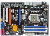
... of this manual occur, the updated version will be available on ASRock website as well. www.asrock.com/support/index.asp 1.1 Package Contents ASRock P55DE Pro / P55DE3 Motherboard (ATX Form Factor: 12.0-in x 8.3-in, 30.5 cm x 21.1 cm) ASRock P55DE Pro / P55DE3 Quick Installation Guide ASRock P55DE Pro / P55DE3 Support CD 2 x Serial ATA (SATA) Data Cables (Optional) 1 x I/O Panel Shield...
... of this manual occur, the updated version will be available on ASRock website as well. www.asrock.com/support/index.asp 1.1 Package Contents ASRock P55DE Pro / P55DE3 Motherboard (ATX Form Factor: 12.0-in x 8.3-in, 30.5 cm x 21.1 cm) ASRock P55DE Pro / P55DE3 Quick Installation Guide ASRock P55DE Pro / P55DE3 Support CD 2 x Serial ATA (SATA) Data Cables (Optional) 1 x I/O Panel Shield...

User Manual
Page 6
... + 1 Power Phase Design - Supports Untied Overclocking Technology (see CAUTION 4) - Supports EM64T CPU - Max. PCIE x1 Gigabit LAN 10/100/1000 Mb/s - Supports Wake-On-LAN I /O - ATX Form Factor: 12.0-in x 8.3-in the LGA1156 Package - Supports Intel® Turbo Boost Technology - Dual Channel DDR3 Memory Technology (see CAUTION 5) - 1 x PCI Express 2.0 x16 slot...
... + 1 Power Phase Design - Supports Untied Overclocking Technology (see CAUTION 4) - Supports EM64T CPU - Max. PCIE x1 Gigabit LAN 10/100/1000 Mb/s - Supports Wake-On-LAN I /O - ATX Form Factor: 12.0-in x 8.3-in the LGA1156 Package - Supports Intel® Turbo Boost Technology - Dual Channel DDR3 Memory Technology (see CAUTION 5) - 1 x PCI Express 2.0 x16 slot...
User Manual
Page 11
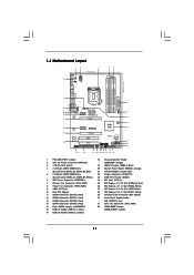
...SPEAKER1 1 1 USB10_11 CLRCMOS1 1 SATAII_3 SATAII_4 SATAII_1 SATAII_2 23 22 21 20 1918 17 16 15 14 6 7 8 9 10 11 12 13 1 PS2_USB_PWR1 Jumper 2 ATX 12V Power Connector (ATX12V1) 3 1156-Pin CPU Socket 4 2 x 240-pin DDR3 DIMM Slots (Dual Channel: DDR3_A2, DDR3_B2, Blue) 5 2 x 240-pin ...DDR3 DIMM Slots (Dual Channel: DDR3_A1, DDR3_B1, White) 6 ATX Power Connector (ATXPWR1) 7 Chassis Fan Connector (CHA_FAN1) 8 Power Fan Connector (PWR_FAN1) 9 16Mb SPI Flash 10 Intel P55 Chipset 11 SATAII Connector (SATAII_3, Red) ...
...SPEAKER1 1 1 USB10_11 CLRCMOS1 1 SATAII_3 SATAII_4 SATAII_1 SATAII_2 23 22 21 20 1918 17 16 15 14 6 7 8 9 10 11 12 13 1 PS2_USB_PWR1 Jumper 2 ATX 12V Power Connector (ATX12V1) 3 1156-Pin CPU Socket 4 2 x 240-pin DDR3 DIMM Slots (Dual Channel: DDR3_A2, DDR3_B2, Blue) 5 2 x 240-pin ...DDR3 DIMM Slots (Dual Channel: DDR3_A1, DDR3_B1, White) 6 ATX Power Connector (ATXPWR1) 7 Chassis Fan Connector (CHA_FAN1) 8 Power Fan Connector (PWR_FAN1) 9 16Mb SPI Flash 10 Intel P55 Chipset 11 SATAII Connector (SATAII_3, Red) ...

User Manual
Page 13
... a safety grounded object before you install motherboard components or change any component, ensure that the power is switched off or the power cord is an ATX form factor (12.0" x 8.3", 30.5 x 21.1 cm) motherboard. Doing so may damage the motherboard. 2.2 Pre-installation Precautions Take note of your motherboard directly on a grounded antistatic...
... a safety grounded object before you install motherboard components or change any component, ensure that the power is switched off or the power cord is an ATX form factor (12.0" x 8.3", 30.5 x 21.1 cm) motherboard. Doing so may damage the motherboard. 2.2 Pre-installation Precautions Take note of your motherboard directly on a grounded antistatic...

User Manual
Page 27
... Connector (24-pin ATXPWR1) (see p.11, No. 6) 12 24 1 13 Please connect an ATX power supply to the ground pin. Chassis and Power Fan Connectors (4-pin CHA_FAN1) (see p.11 No. 7) (3-pin PWR_FAN1) (see p.11 No. 8) GND +12V CHA_FAN_SPEED FAN_SPEED_CONTROL ...
... Connector (24-pin ATXPWR1) (see p.11, No. 6) 12 24 1 13 Please connect an ATX power supply to the ground pin. Chassis and Power Fan Connectors (4-pin CHA_FAN1) (see p.11 No. 7) (3-pin PWR_FAN1) (see p.11 No. 8) GND +12V CHA_FAN_SPEED FAN_SPEED_CONTROL ...

User Manual
Page 28
... supply, please plug your power supply along with Pin 1 and Pin 13. 20-Pin ATX Power Supply Installation 1 13 ATX 12V Power Connector 4 8 (8-pin ATX12V1) (see p.11 No. 32) 4-Pin ATX 12V Power Supply Installation 1 5 RRXD1 DDTR#1 DDSR#1 CCTS#1 1 RRI#1 RRTS#1 GND TTXD1 DDCD#1 This COM1 header supports a serial port ... power supply. Please connect the HDMI_SPDIF connector of HDMI VGA card to this header. 28 To use the 20-pin ATX power supply, please plug your power supply along with Pin 1 and Pin 5. 4 8 Serial port Header (9-pin COM1) (see p.11 No.23) HDMI_SPDIF Header ...
... supply, please plug your power supply along with Pin 1 and Pin 13. 20-Pin ATX Power Supply Installation 1 13 ATX 12V Power Connector 4 8 (8-pin ATX12V1) (see p.11 No. 32) 4-Pin ATX 12V Power Supply Installation 1 5 RRXD1 DDTR#1 DDSR#1 CCTS#1 1 RRI#1 RRTS#1 GND TTXD1 DDCD#1 This COM1 header supports a serial port ... power supply. Please connect the HDMI_SPDIF connector of HDMI VGA card to this header. 28 To use the 20-pin ATX power supply, please plug your power supply along with Pin 1 and Pin 5. 4 8 Serial port Header (9-pin COM1) (see p.11 No.23) HDMI_SPDIF Header ...

Quick Installation Guide
Page 2
... (ATX12V1) 3 1156-Pin CPU Socket 4 2 x 240-pin DDR3 DIMM Slots (Dual Channel: DDR3_A2, DDR3_B2, Blue) 5 2 x 240-pin DDR3 DIMM Slots (Dual Channel: DDR3_A1, DDR3_B1, White) 6 ATX Power Connector (ATXPWR1) 7 Chassis Fan Connector (CHA_FAN1) 8 Power Fan Connector (PWR_FAN1) 9 16Mb SPI Flash 10 Intel P55 Chipset 11 SATAII Connector (SATAII_3, Red) 12 SATAII... (PCIE1, White) 29 Internal Audio Connector: CD1 (Black) 30 Front Panel Audio Header (HD_AUDIO1, Lime) 31 CPU Fan Connector (CPU_FAN1) 32 HDMI_SPDIF Header (HDMI_SPDIF1, Yellow) 2 ASRock P55DE Pro / P55DE3 Motherboard
... (ATX12V1) 3 1156-Pin CPU Socket 4 2 x 240-pin DDR3 DIMM Slots (Dual Channel: DDR3_A2, DDR3_B2, Blue) 5 2 x 240-pin DDR3 DIMM Slots (Dual Channel: DDR3_A1, DDR3_B1, White) 6 ATX Power Connector (ATXPWR1) 7 Chassis Fan Connector (CHA_FAN1) 8 Power Fan Connector (PWR_FAN1) 9 16Mb SPI Flash 10 Intel P55 Chipset 11 SATAII Connector (SATAII_3, Red) 12 SATAII... (PCIE1, White) 29 Internal Audio Connector: CD1 (Black) 30 Front Panel Audio Header (HD_AUDIO1, Lime) 31 CPU Fan Connector (CPU_FAN1) 32 HDMI_SPDIF Header (HDMI_SPDIF1, Yellow) 2 ASRock P55DE Pro / P55DE3 Motherboard

Quick Installation Guide
Page 4
... case any modifications of the motherboard can be updated, the content of the motherboard and step-by-step installation guide. www.asrock.com/support/index.asp 1.1 Package Contents ASRock P55DE Pro / P55DE3 Motherboard (ATX Form Factor: 12.0-in x 8.3-in the Support CD. Because the motherboard specifications and the BIOS software might be found in...
... case any modifications of the motherboard can be updated, the content of the motherboard and step-by-step installation guide. www.asrock.com/support/index.asp 1.1 Package Contents ASRock P55DE Pro / P55DE3 Motherboard (ATX Form Factor: 12.0-in x 8.3-in the Support CD. Because the motherboard specifications and the BIOS software might be found in...

Quick Installation Guide
Page 5
...V4 + 1 Power Phase Design - Max. HD Audio Jack: Side Speaker/Rear Speaker/Central/Bass/ Line in , 30.5 cm x 21.1 cm - ATX Form Factor: 12.0-in x 8.3-in /Front Speaker/Microphone (see CAUTION 2) - Supports Intel® Turbo Boost Technology - Supports EM64T CPU - capacity of...x Powered eSATAII/USB Connectors - 1 x RJ-45 LAN Port with LED (ACT/LINK LED and SPEED LED) - Supports Untied Overclocking Technology (see CAUTION 6) 5 ASRock P55DE Pro / P55DE3 Motherboard English PCIE x1 Gigabit LAN 10/100/1000 Mb/s - Supports DDR3 2400+(OC)/2133(OC)/1866(OC)/1600/ 1333/1066 non-ECC, un...
...V4 + 1 Power Phase Design - Max. HD Audio Jack: Side Speaker/Rear Speaker/Central/Bass/ Line in , 30.5 cm x 21.1 cm - ATX Form Factor: 12.0-in x 8.3-in /Front Speaker/Microphone (see CAUTION 2) - Supports Intel® Turbo Boost Technology - Supports EM64T CPU - capacity of...x Powered eSATAII/USB Connectors - 1 x RJ-45 LAN Port with LED (ACT/LINK LED and SPEED LED) - Supports Untied Overclocking Technology (see CAUTION 6) 5 ASRock P55DE Pro / P55DE3 Motherboard English PCIE x1 Gigabit LAN 10/100/1000 Mb/s - Supports DDR3 2400+(OC)/2133(OC)/1866(OC)/1600/ 1333/1066 non-ECC, un...

Quick Installation Guide
Page 23
English 23 ASRock P55DE Pro / P55DE3 Motherboard For Windows® VistaTM / VistaTM 64-bit OS: Go to the "Front Mic" Tab in "Front Mic" of "Playback" portion. Though this connector. Pin 1-3 Connected 3-Pin Fan Installation ATX Power Connector (24-pin ATXPWR1) (see p.2, No. 6) 12 24 1 13 Please connect an ATX power supply to make the...
English 23 ASRock P55DE Pro / P55DE3 Motherboard For Windows® VistaTM / VistaTM 64-bit OS: Go to the "Front Mic" Tab in "Front Mic" of "Playback" portion. Though this connector. Pin 1-3 Connected 3-Pin Fan Installation ATX Power Connector (24-pin ATXPWR1) (see p.2, No. 6) 12 24 1 13 Please connect an ATX power supply to make the...

Quick Installation Guide
Page 24
...ASRock P55DE Pro / P55DE3 Motherboard To use the 4-pin ATX power supply, please plug your power supply along with Pin 1 and Pin 13. 20-Pin ATX Power Supply Installation 1 13 ATX 12V Power Connector 4 8 (8-pin ATX12V1) (see p.2 No. 2) 1 5 Please connect an ATX 12V power supply to this connector. HDMI_SPDIF Header (3-pin HDMI_SPDIF1) (see p.2 No.23) 4-Pin ATX... HDMI_SPDIF connector of HDMI VGA card to con nect HDMI Digital TV/ projector/LCD devices. To use the 20-pin ATX power supply, please plug your power supply along with Pin 1 and Pin 5. 4 8 Serial port Header (9-pin ...
...ASRock P55DE Pro / P55DE3 Motherboard To use the 4-pin ATX power supply, please plug your power supply along with Pin 1 and Pin 13. 20-Pin ATX Power Supply Installation 1 13 ATX 12V Power Connector 4 8 (8-pin ATX12V1) (see p.2 No. 2) 1 5 Please connect an ATX 12V power supply to this connector. HDMI_SPDIF Header (3-pin HDMI_SPDIF1) (see p.2 No.23) 4-Pin ATX... HDMI_SPDIF connector of HDMI VGA card to con nect HDMI Digital TV/ projector/LCD devices. To use the 20-pin ATX power supply, please plug your power supply along with Pin 1 and Pin 5. 4 8 Serial port Header (9-pin ...