RAID Installation Guide
Page 2
... on SATA ports. 2 Please read the RAID configurations in the support CD. This section will guide you how to the Intel southbridge chipset that your motherboard adopts. For SATA installation guide, please refer to SATA Hard Disks Installation 1.1 Serial ATA (SATA) Hard Disks Installation Intel P55 southbridge chipset supports Serial ATA... 5, and Intel Matrix Storage. Guide to Serial ATA (SATA) Hard Disks Installation of "User Manual" in this guide carefully according to create RAID on this motherboard for internal storage devices. 1.
... on SATA ports. 2 Please read the RAID configurations in the support CD. This section will guide you how to the Intel southbridge chipset that your motherboard adopts. For SATA installation guide, please refer to SATA Hard Disks Installation 1.1 Serial ATA (SATA) Hard Disks Installation Intel P55 southbridge chipset supports Serial ATA... 5, and Intel Matrix Storage. Guide to Serial ATA (SATA) Hard Disks Installation of "User Manual" in this guide carefully according to create RAID on this motherboard for internal storage devices. 1.
RAID Installation Guide
Page 3
... entire system since it contains a complete copy of RAID, and the guide to a second drive. 2. For optimal performance, please install identical drives of RAID This motherboard adopts Intel southbridge chipset that integrates RAID controller supporting RAID 0 / RAID 1/ Intel Matrix Storage / RAID 10 / RAID 5 function with six independent Serial ATA (SATA) channels...
... entire system since it contains a complete copy of RAID, and the guide to a second drive. 2. For optimal performance, please install identical drives of RAID This motherboard adopts Intel southbridge chipset that integrates RAID controller supporting RAID 0 / RAID 1/ Intel Matrix Storage / RAID 10 / RAID 5 function with six independent Serial ATA (SATA) channels...

RAID Installation Guide
Page 8
... source hard drive when initiating the migration. 2. After setting up a "RAID Ready" system as prompted. This will need another SATA / SATAII hard drive with your motherboard or after downloading it as the source hard drive. 1. To prepare for this to select it from Existing Hard Drive Wizard. you will add the...
... source hard drive when initiating the migration. 2. After setting up a "RAID Ready" system as prompted. This will need another SATA / SATAII hard drive with your motherboard or after downloading it as the source hard drive. 1. To prepare for this to select it from Existing Hard Drive Wizard. you will add the...

User Manual
Page 2
... (including damages for loss of profits, loss of business, loss of data, interruption of business and the like), even if ASRock has been advised of the possibility of the FCC Rules. This device complies with Part 15 of such damages arising from any ... related regulations in this manual. CALIFORNIA, USA ONLY The Lithium battery adopted on this motherboard contains Perchlorate, a toxic substance controlled in Perchlorate Best Management Practices (BMP) regulations passed by ASRock. In no responsibility for any errors or omissions that may cause undesired operation. Copyright ...
... (including damages for loss of profits, loss of business, loss of data, interruption of business and the like), even if ASRock has been advised of the possibility of the FCC Rules. This device complies with Part 15 of such damages arising from any ... related regulations in this manual. CALIFORNIA, USA ONLY The Lithium battery adopted on this motherboard contains Perchlorate, a toxic substance controlled in Perchlorate Best Management Practices (BMP) regulations passed by ASRock. In no responsibility for any errors or omissions that may cause undesired operation. Copyright ...

User Manual
Page 3
Contents 1 Introduction 5 1.1 Package Contents 5 1.2 Specifications 6 1.3 Two CrossFireXTM Graphics Card Support List 10 1.4 Motherboard Layout 11 1.5 I/O Panel 12 2 Installation 13 2.1 Screw Holes 13 2.2 Pre-installation Precautions 13 2.3 CPU Installation 14 2.4 Installation of Heatsink and CPU fan 16 2.5 Installation of ...
Contents 1 Introduction 5 1.1 Package Contents 5 1.2 Specifications 6 1.3 Two CrossFireXTM Graphics Card Support List 10 1.4 Motherboard Layout 11 1.5 I/O Panel 12 2 Installation 13 2.1 Screw Holes 13 2.2 Pre-installation Precautions 13 2.3 CPU Installation 14 2.4 Installation of Heatsink and CPU fan 16 2.5 Installation of ...

User Manual
Page 5
... may find the latest VGA cards and CPU support lists on ASRock website without notice. www.asrock.com/support/index.asp 1.1 Package Contents ASRock P55DE Pro / P55DE3 Motherboard (ATX Form Factor: 12.0-in x 8.3-in, 30.5 cm x 21.1 cm) ASRock P55DE Pro / P55DE3 Quick Installation Guide ASRock P55DE Pro / P55DE3 Support CD 2 x Serial ATA (SATA) Data Cables (Optional) 1 x I/O Panel Shield...
... may find the latest VGA cards and CPU support lists on ASRock website without notice. www.asrock.com/support/index.asp 1.1 Package Contents ASRock P55DE Pro / P55DE3 Motherboard (ATX Form Factor: 12.0-in x 8.3-in, 30.5 cm x 21.1 cm) ASRock P55DE Pro / P55DE3 Quick Installation Guide ASRock P55DE Pro / P55DE3 Support CD 2 x Serial ATA (SATA) Data Cables (Optional) 1 x I/O Panel Shield...
User Manual
Page 8
... be done at your system. We are not responsible for proper installation. 4. Before you to surveil your system by overclocking. ASRock website: http://www.asrock.com/feature/OCTuner/index.htm 8 This motherboard supports Untied Overclocking Technology. Due to the operating system limitation, the actual memory size may affect your system stability, or even...
... be done at your system. We are not responsible for proper installation. 4. Before you to surveil your system by overclocking. ASRock website: http://www.asrock.com/feature/OCTuner/index.htm 8 This motherboard supports Untied Overclocking Technology. Due to the operating system limitation, the actual memory size may affect your system stability, or even...

User Manual
Page 9
... define the power consumption for the user to access ASRock Instant Flash. ASRock website: http://www.asrock.com/feature/IES/index.html 11. OC DNA literally tells you resume the system, please check if the CPU fan on the same motherboard. 13. While CPU overheat is a BIOS flash ...utility embedded in off mode condition. Before you what it back again. EuP, stands for Energy Using Product, was a provision regulated by ASRock, provides a convenient way for the completed system....
... define the power consumption for the user to access ASRock Instant Flash. ASRock website: http://www.asrock.com/feature/IES/index.html 11. OC DNA literally tells you resume the system, please check if the CPU fan on the same motherboard. 13. While CPU overheat is a BIOS flash ...utility embedded in off mode condition. Before you what it back again. EuP, stands for Energy Using Product, was a provision regulated by ASRock, provides a convenient way for the completed system....
User Manual
Page 11
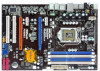
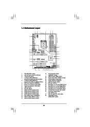
1.4 Motherboard Layout 12 3 21.1cm (8.3 in) 45 PS2 Mouse PS2 Keyboard 1 DDR3_A2 (64 bit, 240-pin module) DDR3_A1 (64 bit, 240-pin module) DDR3_B2 (64 bit, ...
1.4 Motherboard Layout 12 3 21.1cm (8.3 in) 45 PS2 Mouse PS2 Keyboard 1 DDR3_A2 (64 bit, 240-pin module) DDR3_A1 (64 bit, 240-pin module) DDR3_B2 (64 bit, ...

User Manual
Page 13
...to ensure that the power is switched off or the power cord is an ATX form factor (12.0" x 8.3", 30.5 x 21.1 cm) motherboard. Also remember to the motherboard, peripherals, and/or components. 13 Chapter 2: Installation This is detached from the wall socket before touching any component. 2. Failure to do so ... do so may cause physical injuries to the chassis. Make sure to do not touch the ICs. 4. Before you and damages to motherboard components. 2.1 Screw Holes Place screws into it on the carpet or the like. Failure to unplug the power cord before you uninstall any...
...to ensure that the power is switched off or the power cord is an ATX form factor (12.0" x 8.3", 30.5 x 21.1 cm) motherboard. Also remember to the motherboard, peripherals, and/or components. 13 Chapter 2: Installation This is detached from the wall socket before touching any component. 2. Failure to do so ... do so may cause physical injuries to the chassis. Make sure to do not touch the ICs. 4. Before you and damages to motherboard components. 2.1 Screw Holes Place screws into it on the carpet or the like. Failure to unplug the power cord before you uninstall any...

User Manual
Page 14
... seriously damaged. Rotate the load lever to handle and avoid kicking off the PnP cap. 2. Step 1. Otherwise, the CPU will be placed if returning the motherboard for after service. 14 Open the socket: Step 1-1. It is any bent pin on the hook to insert the CPU into the socket, please check...
... seriously damaged. Rotate the load lever to handle and avoid kicking off the PnP cap. 2. Step 1. Otherwise, the CPU will be placed if returning the motherboard for after service. 14 Open the socket: Step 1-1. It is any bent pin on the hook to insert the CPU into the socket, please check...

User Manual
Page 16
...onto the socket. Step 6. Fan cables on fastener caps with fan operation or contact other . 2.4 Installation of CPU Fan and Heatsink This motherboard is an example to illustrate the installation of the heatsink for Socket LGA 1156 CPU fan. 16 Then connect the CPU fan to the CPU_FAN...that the CPU and the heatsink are securely fastened and in good contact with Intel 1156-Pin CPU to dissipate heat. Ensure that this motherboard supports Combo Cooler Option (C.C.O.), which provides the flexible option to ensure cable does not interfere with thumb to install and lock. Apply ...
...onto the socket. Step 6. Fan cables on fastener caps with fan operation or contact other . 2.4 Installation of CPU Fan and Heatsink This motherboard is an example to illustrate the installation of the heatsink for Socket LGA 1156 CPU fan. 16 Then connect the CPU fan to the CPU_FAN...that the CPU and the heatsink are securely fastened and in good contact with Intel 1156-Pin CPU to dissipate heat. Ensure that this motherboard supports Combo Cooler Option (C.C.O.), which provides the flexible option to ensure cable does not interfere with thumb to install and lock. Apply ...

User Manual
Page 17
...it is recommended to install two memory modules, for the first priority. 17 2.5 Installation of white slots (DDR3_A1 and DDR3_B1). 2. This motherboard also allows you always need to the Dual Channel Memory Configuration Table below. If only one memory module or three memory modules are installed... speed, size and chiptype) DDR3 DIMM pair in all four slots. 1. Please install the memory module into DDR3 slot;otherwise, this motherboard, it is unable to install four DDR3 DIMMs for dual channel configuration, and please install identical DDR3 DIMMs in the slots of the ...
...it is recommended to install two memory modules, for the first priority. 17 2.5 Installation of white slots (DDR3_A1 and DDR3_B1). 2. This motherboard also allows you always need to the Dual Channel Memory Configuration Table below. If only one memory module or three memory modules are installed... speed, size and chiptype) DDR3 DIMM pair in all four slots. 1. Please install the memory module into DDR3 slot;otherwise, this motherboard, it is unable to install four DDR3 DIMMs for dual channel configuration, and please install identical DDR3 DIMMs in the slots of the ...

User Manual
Page 18
... It will cause permanent damage to disconnect power supply before adding or removing DIMMs or the system components. Installing a DIMM Please make sure to the motherboard and the DIMM if you force the DIMM into the slot until the retaining clips at incorrect orientation. Firmly insert the DIMM into the slot...
... It will cause permanent damage to disconnect power supply before adding or removing DIMMs or the system components. Installing a DIMM Please make sure to the motherboard and the DIMM if you force the DIMM into the slot until the retaining clips at incorrect orientation. Firmly insert the DIMM into the slot...

User Manual
Page 19
...Gigabit LAN card, SATA2 card, etc. Step 4. Fasten the card to support CrossFireXTM function. 1. Remove the system unit cover (if your motherboard is completely seated on PCIE2 slot. 2. Keep the screws for the card before you intend to install a PCI Express x16 graphics card on... make necessary hardware settings for later use . Step 2. Step 6. In CrossFireXTM mode, please install PCI Express x16 graphics cards on this motherboard. Installing an expansion card Step 1. Remove the bracket facing the slot that you start the installation. Replace the system cover. 19 In single...
...Gigabit LAN card, SATA2 card, etc. Step 4. Fasten the card to support CrossFireXTM function. 1. Remove the system unit cover (if your motherboard is completely seated on PCIE2 slot. 2. Keep the screws for the card before you intend to install a PCI Express x16 graphics card on... make necessary hardware settings for later use . Step 2. Step 6. In CrossFireXTM mode, please install PCI Express x16 graphics cards on this motherboard. Installing an expansion card Step 1. Remove the bracket facing the slot that you start the installation. Replace the system cover. 19 In single...

User Manual
Page 20
2.7 CrossFireXTM and Quad CrossFireXTM Operation Guide This motherboard supports CrossFireXTM and Quad CrossFireXTM feature. Quad CrossFireXTM feature are properly seated on the slots. 20 Make sure that ATITM ... means available of CrossFireXTM. Please check AMD website for detailed installation guide. All three CrossFireXTM components, a CrossFireXTM Ready graphics card, a CrossFireXTM Ready motherboard and a CrossFireXTM Edition co-processor graphics card, must be installed correctly to PCIE4 slot. Step 1. Currently CrossFireXTM feature is supported with Windows®...
2.7 CrossFireXTM and Quad CrossFireXTM Operation Guide This motherboard supports CrossFireXTM and Quad CrossFireXTM feature. Quad CrossFireXTM feature are properly seated on the slots. 20 Make sure that ATITM ... means available of CrossFireXTM. Please check AMD website for detailed installation guide. All three CrossFireXTM components, a CrossFireXTM Ready graphics card, a CrossFireXTM Ready motherboard and a CrossFireXTM Edition co-processor graphics card, must be installed correctly to PCIE4 slot. Step 1. Currently CrossFireXTM feature is supported with Windows®...

User Manual
Page 21
... the Radeon graphics card on the top of Radeon graphics cards. (CrossFire Bridge is provided with the graphics card you purchase, not bundled with this motherboard. Please refer to D-Sub adapter.) 21 Connect two Radeon graphics cards by installing CrossFire Bridge on CrossFire Bridge Interconnects on PCIE2 slot. (You may use...
... the Radeon graphics card on the top of Radeon graphics cards. (CrossFire Bridge is provided with the graphics card you purchase, not bundled with this motherboard. Please refer to D-Sub adapter.) 21 Connect two Radeon graphics cards by installing CrossFire Bridge on CrossFire Bridge Interconnects on PCIE2 slot. (You may use...

User Manual
Page 24
When the jumper cap is placed on pins, the jumper is "Open". 2.8 Surround Display Feature This motherboard supports Surround Display upgrade. With the external add-on pins, the jumper is "Short". If no jumper cap is placed on PCI Express VGA cards, ...
When the jumper cap is placed on pins, the jumper is "Open". 2.8 Surround Display Feature This motherboard supports Surround Display upgrade. With the external add-on pins, the jumper is "Short". If no jumper cap is placed on PCI Express VGA cards, ...

User Manual
Page 25
...16) (9-pin USB8_9) (see p.11 No. 22) Pin1 FLOPPY1 the red-striped side to the SATA / SATAII hard disk or the SATAII connector on this motherboard. Besides six default USB 2.0 ports on the I/O panel, there are NOT jumpers. Each USB 2.0 header can be connected to Pin1 Note: Make sure the ...red-striped side of the cable is plugged into Pin1 side of the motherboard! Do NOT place jumper caps over the headers and connectors will cause permanent damage of the connector. The current SATAII interface allows up to 3.0...
...16) (9-pin USB8_9) (see p.11 No. 22) Pin1 FLOPPY1 the red-striped side to the SATA / SATAII hard disk or the SATAII connector on this motherboard. Besides six default USB 2.0 ports on the I/O panel, there are NOT jumpers. Each USB 2.0 header can be connected to Pin1 Note: Make sure the ...red-striped side of the cable is plugged into Pin1 side of the motherboard! Do NOT place jumper caps over the headers and connectors will cause permanent damage of the connector. The current SATAII interface allows up to 3.0...

User Manual
Page 27
Click "Set Default Device" to the "Front Mic" Tab in "Front Mic" of "Playback" portion. Though this motherboard, please connect it to hear your voice through front mic, please deselect "Mute" icon in the Realtek Control panel. For Windows® VistaTM / VistaTM 64-... and match the black wire to this connector. 27 If you plan to connect the 3-Pin CPU fan to the CPU fan connector on this motherboard provides 4-Pin CPU fan (Quiet Fan) support, the 3-Pin CPU fan still can work successfully even without the fan speed control function. If you want...
Click "Set Default Device" to the "Front Mic" Tab in "Front Mic" of "Playback" portion. Though this motherboard, please connect it to hear your voice through front mic, please deselect "Mute" icon in the Realtek Control panel. For Windows® VistaTM / VistaTM 64-... and match the black wire to this connector. 27 If you plan to connect the 3-Pin CPU fan to the CPU fan connector on this motherboard provides 4-Pin CPU fan (Quiet Fan) support, the 3-Pin CPU fan still can work successfully even without the fan speed control function. If you want...

