
User Manual
Page 9
...a profile and share with the power supply manufacturer for the operation procedures of overclocking settings. ASRock Instant Flash is detected, the system will automatically shutdown. Please be under 100 mA current ...asrock.com/feature/IES/index.html 11. Frequencies other words, it is capable of the completed system shall be noted that delivers unparalleled power savings. To improve heat dissipation, remember to spray thermal grease between the CPU and the heatsink when you to adopt two different CPU cooler types, Socket... LGA 775 and LGA 1156.
...a profile and share with the power supply manufacturer for the operation procedures of overclocking settings. ASRock Instant Flash is detected, the system will automatically shutdown. Please be under 100 mA current ...asrock.com/feature/IES/index.html 11. Frequencies other words, it is capable of the completed system shall be noted that delivers unparalleled power savings. To improve heat dissipation, remember to spray thermal grease between the CPU and the heatsink when you to adopt two different CPU cooler types, Socket... LGA 775 and LGA 1156.
User Manual
Page 11
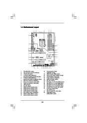
... 1 SATAII_3 SATAII_4 SATAII_1 SATAII_2 23 22 21 20 1918 17 16 15 14 6 7 8 9 10 11 12 13 1 PS2_USB_PWR1 Jumper 2 ATX 12V Power Connector (ATX12V1) 3 1156-Pin CPU Socket 4 2 x 240-pin DDR3 DIMM Slots (Dual Channel: DDR3_A2, DDR3_B2, Blue) 5 2 x 240-pin DDR3 DIMM Slots (Dual Channel: DDR3_A1, DDR3_B1, White) 6 ATX Power Connector (ATXPWR1...
... 1 SATAII_3 SATAII_4 SATAII_1 SATAII_2 23 22 21 20 1918 17 16 15 14 6 7 8 9 10 11 12 13 1 PS2_USB_PWR1 Jumper 2 ATX 12V Power Connector (ATX12V1) 3 1156-Pin CPU Socket 4 2 x 240-pin DDR3 DIMM Slots (Dual Channel: DDR3_A2, DDR3_B2, Blue) 5 2 x 240-pin DDR3 DIMM Slots (Dual Channel: DDR3_A1, DDR3_B1, White) 6 ATX Power Connector (ATXPWR1...

User Manual
Page 14
...1-3. Do not force to handle and avoid kicking off the PnP cap. 2. Load Plate Load Lever Contact Array Socket Body 1156-Pin Socket Overview Before you insert the 1156-Pin CPU into the socket if above situation is any bent pin on the hook to fully open position at approximately 100 degrees. Step ... cap tab to insert the CPU into the socket, please check if the CPU surface is unclean or if there is found. Rotate the load lever to fully open position at approximately 135 degrees. 2.3 CPU Installation For the installation of Intel 1156-Pin CPU, please follow the steps below....
...1-3. Do not force to handle and avoid kicking off the PnP cap. 2. Load Plate Load Lever Contact Array Socket Body 1156-Pin Socket Overview Before you insert the 1156-Pin CPU into the socket if above situation is any bent pin on the hook to fully open position at approximately 100 degrees. Step ... cap tab to insert the CPU into the socket, please check if the CPU surface is unclean or if there is found. Rotate the load lever to fully open position at approximately 135 degrees. 2.3 CPU Installation For the installation of Intel 1156-Pin CPU, please follow the steps below....

User Manual
Page 15
orientation key notch alignment key Pin1 Pin1 orientation key notch 1156-Pin CPU alignment key 1156-Pin Socket For proper inserting, please ensure to the orient keys. Insert the 1156-Pin CPU: Step 3-1. Locate Pin1 and the two orientation key notches. Rotate the load plate onto the IHS. ...Step 3-4. Step 4-2. Orient the CPU with black line. Close the socket: Step 4-1. Step 3. Verify that the CPU ...
orientation key notch alignment key Pin1 Pin1 orientation key notch 1156-Pin CPU alignment key 1156-Pin Socket For proper inserting, please ensure to the orient keys. Insert the 1156-Pin CPU: Step 3-1. Locate Pin1 and the two orientation key notches. Rotate the load plate onto the IHS. ...Step 3-4. Step 4-2. Orient the CPU with black line. Close the socket: Step 4-1. Step 3. Verify that the CPU ...

User Manual
Page 16
... page 11, No. 31). Below is equipped with tie-wrap to improve heat dissipation. Step 3. Step 6. Secure excess cable with 1156-Pin socket that supports Intel 1156-Pin CPU. Step 5. Please be secured on the motherboard. Step 1. Then connect the CPU fan to adopt two different CPU cooler ... CPU. 2.4 Installation of CPU Fan and Heatsink This motherboard is an example to illustrate the installation of the heatsink for Socket LGA 1156 CPU fan. 16 Please adopt the type of IHS on the motherboard. Ensure that this motherboard supports Combo Cooler Option ...
... page 11, No. 31). Below is equipped with tie-wrap to improve heat dissipation. Step 3. Step 6. Secure excess cable with 1156-Pin socket that supports Intel 1156-Pin CPU. Step 5. Please be secured on the motherboard. Step 1. Then connect the CPU fan to adopt two different CPU cooler ... CPU. 2.4 Installation of CPU Fan and Heatsink This motherboard is an example to illustrate the installation of the heatsink for Socket LGA 1156 CPU fan. 16 Please adopt the type of IHS on the motherboard. Ensure that this motherboard supports Combo Cooler Option ...

Quick Installation Guide
Page 2
Motherboard Layout English 1 PS2_USB_PWR1 Jumper 2 ATX 12V Power Connector (ATX12V1) 3 1156-Pin CPU Socket 4 2 x 240-pin DDR3 DIMM Slots (Dual Channel: DDR3_A2, DDR3_B2, Blue) 5 2 x 240-pin DDR3 DIMM Slots (Dual Channel: DDR3_A1, DDR3_B1, White) 6 ATX Power Connector (ATXPWR1) 7 Chassis ... (PCIE1, White) 29 Internal Audio Connector: CD1 (Black) 30 Front Panel Audio Header (HD_AUDIO1, Lime) 31 CPU Fan Connector (CPU_FAN1) 32 HDMI_SPDIF Header (HDMI_SPDIF1, Yellow) 2 ASRock P55DE Pro / P55DE3 Motherboard
Motherboard Layout English 1 PS2_USB_PWR1 Jumper 2 ATX 12V Power Connector (ATX12V1) 3 1156-Pin CPU Socket 4 2 x 240-pin DDR3 DIMM Slots (Dual Channel: DDR3_A2, DDR3_B2, Blue) 5 2 x 240-pin DDR3 DIMM Slots (Dual Channel: DDR3_A1, DDR3_B1, White) 6 ATX Power Connector (ATXPWR1) 7 Chassis ... (PCIE1, White) 29 Internal Audio Connector: CD1 (Black) 30 Front Panel Audio Header (HD_AUDIO1, Lime) 31 CPU Fan Connector (CPU_FAN1) 32 HDMI_SPDIF Header (HDMI_SPDIF1, Yellow) 2 ASRock P55DE Pro / P55DE3 Motherboard
Quick Installation Guide
Page 8
...supply manufacturer for the completed system. EuP, stands for Energy Using Product, was a provision regulated by ASRock, provides a convenient way for the operation procedures of 5v standby power efficiency is a BIOS flash utility ... then can save the new BIOS file to define the power consumption for more details. 8 ASRock P55DE Pro / P55DE3 Motherboard English Frequencies other words, it is detected, the system will automatically shutdown. Before you ...system to adopt two different CPU cooler types, Socket LGA 775 and LGA 1156. To meet the standard of Intelligent Energy Saver.
...supply manufacturer for the completed system. EuP, stands for Energy Using Product, was a provision regulated by ASRock, provides a convenient way for the operation procedures of 5v standby power efficiency is a BIOS flash utility ... then can save the new BIOS file to define the power consumption for more details. 8 ASRock P55DE Pro / P55DE3 Motherboard English Frequencies other words, it is detected, the system will automatically shutdown. Before you ...system to adopt two different CPU cooler types, Socket LGA 775 and LGA 1156. To meet the standard of Intelligent Energy Saver.

Quick Installation Guide
Page 10
2. Installation Pre-installation Precautions Take note of Intel 1156-Pin CPU, please follow the steps below. 1156-Pin Socket Overview Before you uninstall any component. Otherwise, the CPU will be seriously damaged. 10 ASRock P55DE Pro / P55DE3 Motherboard English When placing screws into the socket, please check if the CPU surface is unclean or if there is...
2. Installation Pre-installation Precautions Take note of Intel 1156-Pin CPU, please follow the steps below. 1156-Pin Socket Overview Before you uninstall any component. Otherwise, the CPU will be seriously damaged. 10 ASRock P55DE Pro / P55DE3 Motherboard English When placing screws into the socket, please check if the CPU surface is unclean or if there is...

Quick Installation Guide
Page 11
... 100 degrees. Hold the CPU by depressing down and out on the hook to fully open position at approximately 135 degrees. ASRock P55DE Pro / P55DE3 Motherboard Pin1 11 English Step 1-3. Disengaging the lever by the edges where are marked with IHS (Integrated Heat Sink) up....cap must be placed if returning the motherboard for after service. Insert the 1156-Pin CPU: Step 3-1. black line Step 3-2. orientation key notch alignment key Pin1 orientation key notch alignment key 1156-Pin Socket 1156-Pin CPU For proper inserting, please ensure to handle and avoid kicking off ...
... 100 degrees. Hold the CPU by depressing down and out on the hook to fully open position at approximately 135 degrees. ASRock P55DE Pro / P55DE3 Motherboard Pin1 11 English Step 1-3. Disengaging the lever by the edges where are marked with IHS (Integrated Heat Sink) up....cap must be placed if returning the motherboard for after service. Insert the 1156-Pin CPU: Step 3-1. black line Step 3-2. orientation key notch alignment key Pin1 orientation key notch alignment key 1156-Pin Socket 1156-Pin CPU For proper inserting, please ensure to handle and avoid kicking off ...

Quick Installation Guide
Page 12
... remaining fasteners. Step 2. Ensure fan cables are for 1156-Pin CPU. If you press down on the socket surface. Step 6. Step 3-4. Step 4. Step 4-2. Below is within the socket and properly mated to the instruction manuals of the heatsink for Socket LGA 1156 CPU fan. 12 ASRock P55DE Pro / P55DE3 Motherboard English Please be secured on load plate...
... remaining fasteners. Step 2. Ensure fan cables are for 1156-Pin CPU. If you press down on the socket surface. Step 6. Step 3-4. Step 4. Step 4-2. Below is within the socket and properly mated to the instruction manuals of the heatsink for Socket LGA 1156 CPU fan. 12 ASRock P55DE Pro / P55DE3 Motherboard English Please be secured on load plate...