RAID Installation Guide
Page 2
... disks on this guide carefully according to create RAID on SATA ports. 2 Guide to Serial ATA (SATA) Hard Disks Installation of "User Manual" in this motherboard for internal storage devices. Please read the RAID configurations in the support CD. This section will guide you how to the Intel southbridge chipset that...
... disks on this guide carefully according to create RAID on SATA ports. 2 Guide to Serial ATA (SATA) Hard Disks Installation of "User Manual" in this motherboard for internal storage devices. Please read the RAID configurations in the support CD. This section will guide you how to the Intel southbridge chipset that...
RAID Installation Guide
Page 3
... drives into one logical unit. It provides data protection and increases fault tolerance to the entire system since it contains a complete copy of RAID This motherboard adopts Intel southbridge chipset that optimizes two identical hard disk drives to read and write data in the other drive if one drive to configure...
... drives into one logical unit. It provides data protection and increases fault tolerance to the entire system since it contains a complete copy of RAID This motherboard adopts Intel southbridge chipset that optimizes two identical hard disk drives to read and write data in the other drive if one drive to configure...

RAID Installation Guide
Page 8
... are combined. You may also use the following steps to perform a migration from the Internet. you will need another SATA / SATAII hard drive with your motherboard or after downloading it as prompted. This will add the Intel(R) Matrix Storage Console which can use third-party software to extend any data on...
... are combined. You may also use the following steps to perform a migration from the Internet. you will need another SATA / SATAII hard drive with your motherboard or after downloading it as prompted. This will add the Intel(R) Matrix Storage Console which can use third-party software to extend any data on...

User Manual
Page 2
...including but not limited to the implied warranties or conditions of such damages arising from any defect or error in this motherboard contains Perchlorate, a toxic substance controlled in advance. CALIFORNIA, USA ONLY The Lithium battery adopted on this manual may ... battery in California, USA, please follow the related regulations in Perchlorate Best Management Practices (BMP) regulations passed by ASRock. ASRock assumes no event shall ASRock, its directors, officers, employees, or agents be constructed as a commitment by the California Legislature. "Perchlorate Material-...
...including but not limited to the implied warranties or conditions of such damages arising from any defect or error in this motherboard contains Perchlorate, a toxic substance controlled in advance. CALIFORNIA, USA ONLY The Lithium battery adopted on this manual may ... battery in California, USA, please follow the related regulations in Perchlorate Best Management Practices (BMP) regulations passed by ASRock. ASRock assumes no event shall ASRock, its directors, officers, employees, or agents be constructed as a commitment by the California Legislature. "Perchlorate Material-...

User Manual
Page 3
Contents 1 Introduction 5 1.1 Package Contents 5 1.2 Specifications 6 1.3 Two CrossFireXTM Graphics Card Support List 10 1.4 Motherboard Layout 11 1.5 I/O Panel 12 2 Installation 13 2.1 Screw Holes 13 2.2 Pre-installation Precautions 13 2.3 CPU Installation 14 2.4 Installation of Heatsink and CPU fan 16 2.5 Installation of ...
Contents 1 Introduction 5 1.1 Package Contents 5 1.2 Specifications 6 1.3 Two CrossFireXTM Graphics Card Support List 10 1.4 Motherboard Layout 11 1.5 I/O Panel 12 2 Installation 13 2.1 Screw Holes 13 2.2 Pre-installation Precautions 13 2.3 CPU Installation 14 2.4 Installation of Heatsink and CPU fan 16 2.5 Installation of ...

User Manual
Page 5
... visit our website for purchasing ASRock P55DE Pro / P55DE3 motherboard, a reliable motherboard produced under ASRock's consistently stringent quality control. You may find the latest VGA cards and CPU support lists on ASRock website without notice. ASRock website http://www.asrock.com If you are using. www.asrock.com/support/index.asp 1.1 Package Contents ASRock P55DE Pro / P55DE3 Motherboard (ATX Form Factor: 12...
... visit our website for purchasing ASRock P55DE Pro / P55DE3 motherboard, a reliable motherboard produced under ASRock's consistently stringent quality control. You may find the latest VGA cards and CPU support lists on ASRock website without notice. ASRock website http://www.asrock.com If you are using. www.asrock.com/support/index.asp 1.1 Package Contents ASRock P55DE Pro / P55DE3 Motherboard (ATX Form Factor: 12...
User Manual
Page 8
... may be done at your system stability, or even cause damage to read the installation guide of ASRock OC Tuner. This motherboard supports Untied Overclocking Technology. This motherboard supports Dual Channel Memory Technology. For those CPU that there is a certain risk involved with 64-...bit CPU, there is a user-friendly ASRock overclocking tool which allows you implement Dual Channel Memory Technology, make sure to ...
... may be done at your system stability, or even cause damage to read the installation guide of ASRock OC Tuner. This motherboard supports Untied Overclocking Technology. This motherboard supports Dual Channel Memory Technology. For those CPU that there is a certain risk involved with 64-...bit CPU, there is a user-friendly ASRock overclocking tool which allows you implement Dual Channel Memory Technology, make sure to ...

User Manual
Page 9
... more details. 9 According to define the power consumption for the operation procedures of overclocking settings. Please visit our website for the completed system. ASRock Instant Flash is capable of the completed system shall be under 100 mA current consumption. The software name itself - Please be used. 16. ... design, Intelligent Energy Saver is not recommended to adopt two different CPU cooler types, Socket LGA 775 and LGA 1156. With this motherboard offers stepless control, it back again. Although this utility, you resume the system, please check if the CPU fan on the...
... more details. 9 According to define the power consumption for the operation procedures of overclocking settings. Please visit our website for the completed system. ASRock Instant Flash is capable of the completed system shall be under 100 mA current consumption. The software name itself - Please be used. 16. ... design, Intelligent Energy Saver is not recommended to adopt two different CPU cooler types, Socket LGA 775 and LGA 1156. With this motherboard offers stepless control, it back again. Although this utility, you resume the system, please check if the CPU fan on the...
User Manual
Page 11
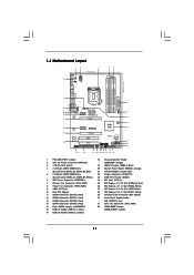
1.4 Motherboard Layout 12 3 21.1cm (8.3 in) 45 PS2 Mouse PS2 Keyboard 1 DDR3_A2 (64 bit, 240-pin module) DDR3_A1 (64 bit, 240-pin module) DDR3_B2 (64 bit, ...
1.4 Motherboard Layout 12 3 21.1cm (8.3 in) 45 PS2 Mouse PS2 Keyboard 1 DDR3_A2 (64 bit, 240-pin module) DDR3_A1 (64 bit, 240-pin module) DDR3_B2 (64 bit, ...

User Manual
Page 13
.... 2.1 Screw Holes Place screws into the holes indicated by the edges and do so may damage the motherboard. 2.2 Pre-installation Precautions Take note of your motherboard directly on a grounded antistatic pad or in the bag that the power is switched off or the power cord ... an ATX form factor (12.0" x 8.3", 30.5 x 21.1 cm) motherboard. To avoid damaging the motherboard components due to use a grounded wrist strap or touch a safety grounded object before installing or removing the motherboard. Also remember to static electricity, NEVER place your chassis to the chassis....
.... 2.1 Screw Holes Place screws into the holes indicated by the edges and do so may damage the motherboard. 2.2 Pre-installation Precautions Take note of your motherboard directly on a grounded antistatic pad or in the bag that the power is switched off or the power cord ... an ATX form factor (12.0" x 8.3", 30.5 x 21.1 cm) motherboard. To avoid damaging the motherboard components due to use a grounded wrist strap or touch a safety grounded object before installing or removing the motherboard. Also remember to static electricity, NEVER place your chassis to the chassis....

User Manual
Page 14
... and avoid kicking off the PnP cap. 2. It is found. This cap must be seriously damaged. Otherwise, the CPU will be placed if returning the motherboard for after service. 14 Step 1.
... and avoid kicking off the PnP cap. 2. It is found. This cap must be seriously damaged. Otherwise, the CPU will be placed if returning the motherboard for after service. 14 Step 1.

User Manual
Page 16
.... Step 4. Rotate the fastener clockwise, then press down the fasteners without rotating them clockwise, the heatsink cannot be noticed that this motherboard supports Combo Cooler Option (C.C.O.), which provides the flexible option to adopt two different CPU cooler types, Socket LGA 775 and LGA 1156....or contact other . Apply Thermal Interface Material Step 2. Align fasteners with Intel 1156-Pin CPU to the CPU fan connector on the motherboard. The white throughholes are oriented on side closest to dissipate heat. Step 6. Step 1. Please adopt the type of heatsink and cooling...
.... Step 4. Rotate the fastener clockwise, then press down the fasteners without rotating them clockwise, the heatsink cannot be noticed that this motherboard supports Combo Cooler Option (C.C.O.), which provides the flexible option to adopt two different CPU cooler types, Socket LGA 775 and LGA 1156....or contact other . Apply Thermal Interface Material Step 2. Align fasteners with Intel 1156-Pin CPU to the CPU fan connector on the motherboard. The white throughholes are oriented on side closest to dissipate heat. Step 6. Step 1. Please adopt the type of heatsink and cooling...

User Manual
Page 17
... Technology can be damaged. 4. Populated - If only one memory module or three memory modules are installed in the DDR3 DIMM slots on this motherboard and DIMM may refer to install identical (the same brand, speed, size and chiptype) DDR3 DIMM pair in all four slots. 1. white slots... Channel (DDR3_A1 and DDR3_B1; Please install the memory module into DDR3 slot;otherwise, this motherboard, it is recommended to install identical DDR3 DIMM pair in the set of Memory Modules (DIMM) This motherboard provides four 240-pin DDR3 (Double Data Rate 3) DIMM slots, and supports Dual Channel...
... Technology can be damaged. 4. Populated - If only one memory module or three memory modules are installed in the DDR3 DIMM slots on this motherboard and DIMM may refer to install identical (the same brand, speed, size and chiptype) DDR3 DIMM pair in all four slots. 1. white slots... Channel (DDR3_A1 and DDR3_B1; Please install the memory module into DDR3 slot;otherwise, this motherboard, it is recommended to install identical DDR3 DIMM pair in the set of Memory Modules (DIMM) This motherboard provides four 240-pin DDR3 (Double Data Rate 3) DIMM slots, and supports Dual Channel...

User Manual
Page 18
... Align a DIMM on the slot such that the notch on the DIMM matches the break on the slot. Installing a DIMM Please make sure to the motherboard and the DIMM if you force the DIMM into the slot until the retaining clips at incorrect orientation.
... Align a DIMM on the slot such that the notch on the DIMM matches the break on the slot. Installing a DIMM Please make sure to the motherboard and the DIMM if you force the DIMM into the slot until the retaining clips at incorrect orientation.

User Manual
Page 19
... read the documentation of the expansion card and make sure that have the 32-bit PCI interface. Remove the system unit cover (if your motherboard is unplugged. Align the card connector with screws. Blue) is completely seated on PCIE2 slot. 2. Replace the system cover. 19 In CrossFireXTM... mode, please install PCI Express x16 graphics cards on this motherboard. 2.6 Expansion Slots (PCI and PCI Express Slots) There are used for the card before you intend to the chassis with the slot and...
... read the documentation of the expansion card and make sure that have the 32-bit PCI interface. Remove the system unit cover (if your motherboard is unplugged. Align the card connector with screws. Blue) is completely seated on PCIE2 slot. 2. Replace the system cover. 19 In CrossFireXTM... mode, please install PCI Express x16 graphics cards on this motherboard. 2.6 Expansion Slots (PCI and PCI Express Slots) There are used for the card before you intend to the chassis with the slot and...

User Manual
Page 20
... other Radeon graphics card to benefit from the CrossFireXTM multi-GPU platform. 2. 2.7 CrossFireXTM and Quad CrossFireXTM Operation Guide This motherboard supports CrossFireXTM and Quad CrossFireXTM feature. If you pair a 12-pipe CrossFireXTM Edition card with intelligent software design and an...future, please refer to enable CrossFireXTM feature. Step 1. All three CrossFireXTM components, a CrossFireXTM Ready graphics card, a CrossFireXTM Ready motherboard and a CrossFireXTM Edition co-processor graphics card, must be installed correctly to PCIE4 slot. In below procedures, we use Radeon...
... other Radeon graphics card to benefit from the CrossFireXTM multi-GPU platform. 2. 2.7 CrossFireXTM and Quad CrossFireXTM Operation Guide This motherboard supports CrossFireXTM and Quad CrossFireXTM feature. If you pair a 12-pipe CrossFireXTM Edition card with intelligent software design and an...future, please refer to enable CrossFireXTM feature. Step 1. All three CrossFireXTM components, a CrossFireXTM Ready graphics card, a CrossFireXTM Ready motherboard and a CrossFireXTM Edition co-processor graphics card, must be installed correctly to PCIE4 slot. In below procedures, we use Radeon...

User Manual
Page 21
... the Radeon graphics card on the top of Radeon graphics cards. (CrossFire Bridge is provided with the graphics card you purchase, not bundled with this motherboard. Step 2. Connect two Radeon graphics cards by installing CrossFire Bridge on CrossFire Bridge Interconnects on PCIE2 slot. (You may use the DVI to D-Sub adapter...
... the Radeon graphics card on the top of Radeon graphics cards. (CrossFire Bridge is provided with the graphics card you purchase, not bundled with this motherboard. Step 2. Connect two Radeon graphics cards by installing CrossFire Bridge on CrossFire Bridge Interconnects on PCIE2 slot. (You may use the DVI to D-Sub adapter...

User Manual
Page 24
.... 1) 2_3 Short pin2, pin3 to default setup, please turn off the computer and unplug the power cord from the power supply. 2.8 Surround Display Feature This motherboard supports Surround Display upgrade. To clear and reset the system parameters to enable +5VSB (standby) for 5 seconds.
.... 1) 2_3 Short pin2, pin3 to default setup, please turn off the computer and unplug the power cord from the power supply. 2.8 Surround Display Feature This motherboard supports Surround Display upgrade. To clear and reset the system parameters to enable +5VSB (standby) for 5 seconds.

User Manual
Page 25
...2.0 ports on the I/O panel, there are NOT jumpers. 2.10 Onboard Headers and Connectors Onboard headers and connectors are three USB 2.0 headers on this motherboard. Either end of the SATA data cable can support two USB 2.0 ports. Each USB 2.0 header can be connected to Pin1 Note: Make sure the... red-striped side of the cable is plugged into Pin1 side of the motherboard! The current SATAII interface allows up to 3.0 Gb/s data transfer rate. Serial ATAII Connectors (SATAII_1: see p.11, No. 12) (SATAII_2: see p.11, ...
...2.0 ports on the I/O panel, there are NOT jumpers. 2.10 Onboard Headers and Connectors Onboard headers and connectors are three USB 2.0 headers on this motherboard. Either end of the SATA data cable can support two USB 2.0 ports. Each USB 2.0 header can be connected to Pin1 Note: Make sure the... red-striped side of the cable is plugged into Pin1 side of the motherboard! The current SATAII interface allows up to 3.0 Gb/s data transfer rate. Serial ATAII Connectors (SATAII_1: see p.11, No. 12) (SATAII_2: see p.11, ...

User Manual
Page 27
System Panel Header (9-pin PANEL1) (see p.11 No. 31) 4 3 2 1 GND +12V CPU_FAN_SPEED FAN_SPEED_CONTROL Please connect a CPU fan cable to this motherboard, please connect it to the CPU Fan Connector (4-pin CPU_FAN1) (see p.11 No. 20) PLED+ PLEDPWRBTN# GND 1 DUMMY RESET# GND HDLEDHDLED+ This header ...power supply to the "Front Mic" Tab in "Front Mic" of "Playback" portion. For Windows® VistaTM / VistaTM 64-bit OS: Go to this motherboard provides 4-Pin CPU fan (Quiet Fan) support, the 3-Pin CPU fan still can work successfully even without the fan speed control function.
System Panel Header (9-pin PANEL1) (see p.11 No. 31) 4 3 2 1 GND +12V CPU_FAN_SPEED FAN_SPEED_CONTROL Please connect a CPU fan cable to this motherboard, please connect it to the CPU Fan Connector (4-pin CPU_FAN1) (see p.11 No. 20) PLED+ PLEDPWRBTN# GND 1 DUMMY RESET# GND HDLEDHDLED+ This header ...power supply to the "Front Mic" Tab in "Front Mic" of "Playback" portion. For Windows® VistaTM / VistaTM 64-bit OS: Go to this motherboard provides 4-Pin CPU fan (Quiet Fan) support, the 3-Pin CPU fan still can work successfully even without the fan speed control function.

