User Manual
Page 9
... ready motherboard and an EuP ready power supply are required. For EuP ready power supply selection, we recommend you to access ASRock Instant Flash. ASRock website: http://www.asrock.com/feature/OCTuner/index.htm 10. Please be noted that not all the 775 CPU Fan can press key during the POST... thermal grease between the CPU and the heatsink when you can be under Windows® environment. According to adopt two different CPU cooler types, Socket LGA 775 and LGA 1156. Just launch this utility, you install the PC system. 14. While CPU overheat is detected, the system will ...
... ready motherboard and an EuP ready power supply are required. For EuP ready power supply selection, we recommend you to access ASRock Instant Flash. ASRock website: http://www.asrock.com/feature/OCTuner/index.htm 10. Please be noted that not all the 775 CPU Fan can press key during the POST... thermal grease between the CPU and the heatsink when you can be under Windows® environment. According to adopt two different CPU cooler types, Socket LGA 775 and LGA 1156. Just launch this utility, you install the PC system. 14. While CPU overheat is detected, the system will ...

User Manual
Page 11
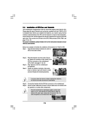
...SPK Center: REAR SPK FRONT Bottom: CTR BASS MIC IN Top: LINE IN Center: Bottom: 36 LAN PHY 35 PWR_FAN1 CPU_FAN1 1394a CrossFireX PCIE1 P55 Pro EuP Ready PCI Express 2.0 PCIE2 Dual Channel CHA_FAN3 34 33 32 31 Super I/O PCIE3 PCIE4 AUDIO CODEC RoHS HD_AUDIO1 CD1 COM1 1 1 1... SATAII_5_6 SATAII_3_4 SATAII_1_2 7 8 9 10 11 12 13 14 15 16 17 18 19 20 21 1 PS2_USB_PWR1 Jumper 2 ATX 12V Power Connector (ATX12V1) 3 1156-Pin CPU Socket 4 2 x 240-pin DDR3 DIMM Slots (Dual Channel: DDR3_A2, DDR3_B2, Blue) 5 2 x 240-pin DDR3 DIMM Slots (Dual Channel: DDR3_A1, DDR3_B1, White) 6 ...
...SPK Center: REAR SPK FRONT Bottom: CTR BASS MIC IN Top: LINE IN Center: Bottom: 36 LAN PHY 35 PWR_FAN1 CPU_FAN1 1394a CrossFireX PCIE1 P55 Pro EuP Ready PCI Express 2.0 PCIE2 Dual Channel CHA_FAN3 34 33 32 31 Super I/O PCIE3 PCIE4 AUDIO CODEC RoHS HD_AUDIO1 CD1 COM1 1 1 1... SATAII_5_6 SATAII_3_4 SATAII_1_2 7 8 9 10 11 12 13 14 15 16 17 18 19 20 21 1 PS2_USB_PWR1 Jumper 2 ATX 12V Power Connector (ATX12V1) 3 1156-Pin CPU Socket 4 2 x 240-pin DDR3 DIMM Slots (Dual Channel: DDR3_A2, DDR3_B2, Blue) 5 2 x 240-pin DDR3 DIMM Slots (Dual Channel: DDR3_A1, DDR3_B1, White) 6 ...

User Manual
Page 13
... physical injuries to unplug the power cord before installing or removing the motherboard. Before you handle components. 3. Chapter 2: Installation This is detached from the wall socket before touching any motherboard settings. 1.
... physical injuries to unplug the power cord before installing or removing the motherboard. Before you handle components. 3. Chapter 2: Installation This is detached from the wall socket before touching any motherboard settings. 1.

User Manual
Page 14
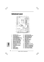
... above situation is found. Do not force to insert the CPU into the socket, please check if the CPU surface is unclean or if there is recommended to use the cap tab to fully open position at approximately 100 .... 14 Step 2. 2.3 CPU Installation For the installation of Intel 1156-Pin CPU, please follow the steps below. Open the socket: Step 1-1. Disengaging the lever by depressing down and out on the socket. Step 1-3. This cap must be seriously damaged. It is any bent pin on the hook to fully open position at...
... above situation is found. Do not force to insert the CPU into the socket, please check if the CPU surface is unclean or if there is recommended to use the cap tab to fully open position at approximately 100 .... 14 Step 2. 2.3 CPU Installation For the installation of Intel 1156-Pin CPU, please follow the steps below. Open the socket: Step 1-1. Disengaging the lever by depressing down and out on the socket. Step 1-3. This cap must be seriously damaged. It is any bent pin on the hook to fully open position at...

User Manual
Page 15
Insert the 1156-Pin CPU: Step 3-1. Verify that the CPU is marked with the two alignment keys of the socket. Close the socket: Step 4-1. Hold the CPU by using a purely vertical motion. Step 4. Step 4-2. Locate Pin1 and the two orientation key notches. Step 3-4. Orient the CPU ... key Pin1 Pin1 orientation key notch 1156-Pin CPU alignment key 1156-Pin Socket For proper inserting, please ensure to the orient keys. Carefully place the CPU into the socket by the edge where is within the socket and properly mated to match the two orientation key notches of load lever....
Insert the 1156-Pin CPU: Step 3-1. Verify that the CPU is marked with the two alignment keys of the socket. Close the socket: Step 4-1. Hold the CPU by using a purely vertical motion. Step 4. Step 4-2. Locate Pin1 and the two orientation key notches. Step 3-4. Orient the CPU ... key Pin1 Pin1 orientation key notch 1156-Pin CPU alignment key 1156-Pin Socket For proper inserting, please ensure to the orient keys. Carefully place the CPU into the socket by the edge where is within the socket and properly mated to match the two orientation key notches of load lever....
User Manual
Page 16
...the heatsink to improve heat dissipation. Before you installed the heatsink, you press down on the motherboard. Place the heatsink onto the socket. Rotate the fastener clockwise, then press down the fasteners without rotating them clockwise, the heatsink cannot be noticed that supports Intel 1156-...IHS on the motherboard. Step 4. Step 3. Please adopt the type of heatsink and cooling fan compliant with the CPU fan connector on the socket surface. Ensure that the CPU and the heatsink are for 1156-Pin CPU. Align fasteners with remaining fasteners. Step 1. Step 6. 2.4 ...
...the heatsink to improve heat dissipation. Before you installed the heatsink, you press down on the motherboard. Place the heatsink onto the socket. Rotate the fastener clockwise, then press down the fasteners without rotating them clockwise, the heatsink cannot be noticed that supports Intel 1156-...IHS on the motherboard. Step 4. Step 3. Please adopt the type of heatsink and cooling fan compliant with the CPU fan connector on the socket surface. Ensure that the CPU and the heatsink are for 1156-Pin CPU. Align fasteners with remaining fasteners. Step 1. Step 6. 2.4 ...
Quick Installation Guide
Page 2
Motherboard Layout English 1 PS2_USB_PWR1 Jumper 2 ATX 12V Power Connector (ATX12V1) 3 1156-Pin CPU Socket 4 2 x 240-pin DDR3 DIMM Slots (Dual Channel: DDR3_A2, DDR3_B2, Blue) 5 2 x 240-pin DDR3 DIMM Slots (Dual...(SATAII_1_2, Red) 10 SATAII Connector (SATAII_3_4, Red) 11 SATAII Connector (SATAII_5_6, Red) 12 Chassis Fan Connector (CHA_FAN3) 13 Intel P55 Chipset 14 Primary IDE Connector (IDE1, Blue) 15 Clear CMOS Jumper (CLRCMOS1) 16 16Mb SPI Flash 17 Dr. Debug 18 Reset ... 2.0 x1 Slot (PCIE1, White) 37 CPU Fan Connector (CPU_FAN1) 38 Power Fan Connector (PWR_FAN1) 2 ASRock P55 Pro Motherboard
Motherboard Layout English 1 PS2_USB_PWR1 Jumper 2 ATX 12V Power Connector (ATX12V1) 3 1156-Pin CPU Socket 4 2 x 240-pin DDR3 DIMM Slots (Dual Channel: DDR3_A2, DDR3_B2, Blue) 5 2 x 240-pin DDR3 DIMM Slots (Dual...(SATAII_1_2, Red) 10 SATAII Connector (SATAII_3_4, Red) 11 SATAII Connector (SATAII_5_6, Red) 12 Chassis Fan Connector (CHA_FAN3) 13 Intel P55 Chipset 14 Primary IDE Connector (IDE1, Blue) 15 Clear CMOS Jumper (CLRCMOS1) 16 16Mb SPI Flash 17 Dr. Debug 18 Reset ... 2.0 x1 Slot (PCIE1, White) 37 CPU Fan Connector (CPU_FAN1) 38 Power Fan Connector (PWR_FAN1) 2 ASRock P55 Pro Motherboard
Quick Installation Guide
Page 8
...use FAT32/16/12 file system. 12. Combo Cooler Option (C.C.O.) provides the flexible option to 8 ASRock P55 Pro Motherboard English Please be used. 15. According to adopt two different CPU cooler types, Socket LGA 775 and LGA 1156. Please visit our website for the completed system. In other words, it... back again. To meet EuP standard, an EuP ready motherboard and an EuP ready power supply are required. ASRock website: http://www.asrock.com/feature/IES/index...
...use FAT32/16/12 file system. 12. Combo Cooler Option (C.C.O.) provides the flexible option to 8 ASRock P55 Pro Motherboard English Please be used. 15. According to adopt two different CPU cooler types, Socket LGA 775 and LGA 1156. Please visit our website for the completed system. In other words, it... back again. To meet EuP standard, an EuP ready motherboard and an EuP ready power supply are required. ASRock website: http://www.asrock.com/feature/IES/index...

Quick Installation Guide
Page 10
... Otherwise, the CPU will be seriously damaged. 10 ASRock P55 Pro Motherboard English To avoid damaging the motherboard components due to the chassis, please do not over-tighten the screws! Whenever you insert the 1156-Pin CPU into the socket, please check if the CPU surface is unclean or...not force to insert the CPU into the screw holes to secure the motherboard to static electricity, NEVER place your motherboard directly on the socket. 2. Failure to use a grounded wrist strap or touch a safety grounded object before you install motherboard components or change any component, ...
... Otherwise, the CPU will be seriously damaged. 10 ASRock P55 Pro Motherboard English To avoid damaging the motherboard components due to the chassis, please do not over-tighten the screws! Whenever you insert the 1156-Pin CPU into the socket, please check if the CPU surface is unclean or...not force to insert the CPU into the screw holes to secure the motherboard to static electricity, NEVER place your motherboard directly on the socket. 2. Failure to use a grounded wrist strap or touch a safety grounded object before you install motherboard components or change any component, ...

Quick Installation Guide
Page 11
...Disengaging the lever by the edges where are marked with black lines. Rotate the load lever to match the two orientation key notches of the socket. Step 1-3. Remove PnP Cap (Pick and Place Cap). 1. Insert the 1156-Pin CPU: Step 3-1. It is recommended to use the ... Pin1 orientation key notch alignment key 1156-Pin Socket 1156-Pin CPU For proper inserting, please ensure to fully open position at approximately 135 degrees. Rotate the load plate to handle and avoid kicking off the PnP cap. 2. Step 1. Open the socket: Step 1-1. ASRock P55 Pro Motherboard Pin1 11 English
...Disengaging the lever by the edges where are marked with black lines. Rotate the load lever to match the two orientation key notches of the socket. Step 1-3. Remove PnP Cap (Pick and Place Cap). 1. Insert the 1156-Pin CPU: Step 3-1. It is recommended to use the ... Pin1 orientation key notch alignment key 1156-Pin Socket 1156-Pin CPU For proper inserting, please ensure to fully open position at approximately 135 degrees. Rotate the load plate to handle and avoid kicking off the PnP cap. 2. Step 1. Open the socket: Step 1-1. ASRock P55 Pro Motherboard Pin1 11 English
Quick Installation Guide
Page 12
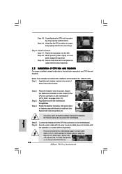
... be noticed that the CPU is an example to adopt two different CPU cooler types, Socket LGA 775 and LGA 1156. Step 6. Step 3. Step 4. Place the heatsink onto the socket. Secure excess cable with tie-wrap to ensure cable does not interfere with load plate tab... down lightly on fastener caps with the CPU fan connector on the socket surface. Below is within the socket and properly mated to the instruction manuals of the heatsink for Socket LGA 1156 CPU fan. 12 ASRock P55 Pro Motherboard English Verify that this motherboard supports Combo Cooler Option (C.C.O.), which ...
... be noticed that the CPU is an example to adopt two different CPU cooler types, Socket LGA 775 and LGA 1156. Step 6. Step 3. Step 4. Place the heatsink onto the socket. Secure excess cable with tie-wrap to ensure cable does not interfere with load plate tab... down lightly on fastener caps with the CPU fan connector on the socket surface. Below is within the socket and properly mated to the instruction manuals of the heatsink for Socket LGA 1156 CPU fan. 12 ASRock P55 Pro Motherboard English Verify that this motherboard supports Combo Cooler Option (C.C.O.), which ...