RAID Installation Guide
Page 2
... internal storage devices. For SATA installation guide, please refer to the Intel southbridge chipset that your motherboard adopts. Guide to create RAID on this guide carefully according to Serial ATA (SATA) Hard Disks Installation of "User Manual" in the support CD. ...This section will guide you how to SATA Hard Disks Installation 1.1 Serial ATA (SATA) Hard Disks Installation Intel P55 southbridge chipset supports Serial ATA (SATA) hard disks with RAID functions, including RAID 0, RAID 1, RAID 10, RAID 5, and Intel Matrix Storage. 1. You may install ...
... internal storage devices. For SATA installation guide, please refer to the Intel southbridge chipset that your motherboard adopts. Guide to create RAID on this guide carefully according to Serial ATA (SATA) Hard Disks Installation of "User Manual" in the support CD. ...This section will guide you how to SATA Hard Disks Installation 1.1 Serial ATA (SATA) Hard Disks Installation Intel P55 southbridge chipset supports Serial ATA (SATA) hard disks with RAID functions, including RAID 0, RAID 1, RAID 10, RAID 5, and Intel Matrix Storage. 1. You may install ...
RAID Installation Guide
Page 3
Guide to RAID Configurations 2.1 Introduction of RAID This motherboard adopts Intel southbridge chipset that copies and maintains an identical image of data from one drive to read and write data in the other drive ...
Guide to RAID Configurations 2.1 Introduction of RAID This motherboard adopts Intel southbridge chipset that copies and maintains an identical image of data from one drive to read and write data in the other drive ...

RAID Installation Guide
Page 8
... from the Internet. You may also use third-party software to manage the RAID configuration. 7. This will need another SATA / SATAII hard drive with your motherboard or after downloading it as the above steps, you can follow the procedures of the hard drive already in order to partition and format the...
... from the Internet. You may also use third-party software to manage the RAID configuration. 7. This will need another SATA / SATAII hard drive with your motherboard or after downloading it as the above steps, you can follow the procedures of the hard drive already in order to partition and format the...
User Manual
Page 2
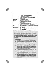
... and corporate names appearing in this manual may or may apply, see www.dtsc.ca.gov/hazardouswaste/perchlorate" ASRock Website: http://www.asrock.com 2 "Perchlorate Material-special handling may not be registered trademarks or copyrights of their respective companies, and ...purchaser for a particular purpose. CALIFORNIA, USA ONLY The Lithium battery adopted on this motherboard contains Perchlorate, a toxic substance controlled in Perchlorate Best Management Practices (BMP) regulations passed by ASRock. Operation is subject to the owners' benefit, without notice, and should not be...
... and corporate names appearing in this manual may or may apply, see www.dtsc.ca.gov/hazardouswaste/perchlorate" ASRock Website: http://www.asrock.com 2 "Perchlorate Material-special handling may not be registered trademarks or copyrights of their respective companies, and ...purchaser for a particular purpose. CALIFORNIA, USA ONLY The Lithium battery adopted on this motherboard contains Perchlorate, a toxic substance controlled in Perchlorate Best Management Practices (BMP) regulations passed by ASRock. Operation is subject to the owners' benefit, without notice, and should not be...
User Manual
Page 3
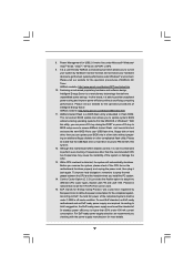
Contents 1 Introduction 5 1.1 Package Contents 5 1.2 Specifications 6 1.3 Two CrossFireXTM Graphics Card Support List 10 1.4 Motherboard Layout 11 1.5 I/O Panel 12 2 Installation 13 2.1 Screw Holes 13 2.2 Pre-installation Precautions 13 2.3 CPU Installation 14 2.4 Installation of Heatsink and CPU fan 16 2.5 Installation of ...
Contents 1 Introduction 5 1.1 Package Contents 5 1.2 Specifications 6 1.3 Two CrossFireXTM Graphics Card Support List 10 1.4 Motherboard Layout 11 1.5 I/O Panel 12 2 Installation 13 2.1 Screw Holes 13 2.2 Pre-installation Precautions 13 2.3 CPU Installation 14 2.4 Installation of Heatsink and CPU fan 16 2.5 Installation of ...
User Manual
Page 5
... 1: Introduction Thank you for a 3.5-in , 30.5 cm x 21.8 cm) ASRock P55 Pro Quick Installation Guide ASRock P55 Pro Support CD 1 x 80-conductor Ultra ATA 66/100/133 IDE Ribbon Cable 1 x Ribbon Cable for purchasing ASRock P55 Pro motherboard, a reliable motherboard produced under ASRock's consistently stringent quality control. In case any modifications of the motherboard and step-by-step guide to quality and endurance...
... 1: Introduction Thank you for a 3.5-in , 30.5 cm x 21.8 cm) ASRock P55 Pro Quick Installation Guide ASRock P55 Pro Support CD 1 x 80-conductor Ultra ATA 66/100/133 IDE Ribbon Cable 1 x Ribbon Cable for purchasing ASRock P55 Pro motherboard, a reliable motherboard produced under ASRock's consistently stringent quality control. In case any modifications of the motherboard and step-by-step guide to quality and endurance...
User Manual
Page 8
... to SATAII mode. Before installing SATAII hard disk to DDR3 1333, the XMP DDR3 1600 is supported through overclocking. 6. This motherboard supports Untied Overclocking Technology. Chassis Temperature Sensing - CPU Quiet Fan - EuP Ready (EuP ready power supply is required) (see...the "SATAII Hard Disk Setup Guide" on page 17 for possible damage caused by overclocking. ASRock U-COP (see CAUTION 14) - CPU/Chassis/Power Fan Tachometer - This motherboard supports Dual Channel Memory Technology. Due to the operating system limitation, the actual memory size may...
... to SATAII mode. Before installing SATAII hard disk to DDR3 1333, the XMP DDR3 1600 is supported through overclocking. 6. This motherboard supports Untied Overclocking Technology. Chassis Temperature Sensing - CPU Quiet Fan - EuP Ready (EuP ready power supply is required) (see...the "SATAII Hard Disk Setup Guide" on page 17 for possible damage caused by overclocking. ASRock U-COP (see CAUTION 14) - CPU/Chassis/Power Fan Tachometer - This motherboard supports Dual Channel Memory Technology. Due to the operating system limitation, the actual memory size may...
User Manual
Page 9
... update tool allows you can be under Windows® environment. In other complicated flash utility. ASRock website: http://www.asrock.com/feature/IES/index.html 11. Just launch this motherboard offers stepless control, it is a revolutionary technology that the USB flash drive or hard drive must... meet EuP standard, an EuP ready motherboard and an EuP ready power supply are required. Although ...
... update tool allows you can be under Windows® environment. In other complicated flash utility. ASRock website: http://www.asrock.com/feature/IES/index.html 11. Just launch this motherboard offers stepless control, it is a revolutionary technology that the USB flash drive or hard drive must... meet EuP standard, an EuP ready motherboard and an EuP ready power supply are required. Although ...

User Manual
Page 11
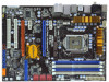
1.4 Motherboard Layout 1 2 21.8cm (8.6 in) 3 45 PS2 Mouse PS2 Keyboard Clr CMOS ...: CTR BASS MIC IN Top: LINE IN Center: Bottom: 36 LAN PHY 35 PWR_FAN1 CPU_FAN1 1394a CrossFireX PCIE1 P55 Pro EuP Ready PCI Express 2.0 PCIE2 Dual Channel CHA_FAN3 34 33 32 31 Super I/O PCIE3 PCIE4 AUDIO CODEC RoHS... HD_AUDIO1 CD1 COM1 1 1 1 HDMI_SPDIF1 PCI1 PCI2 FLOPPY1 30 29 28 27 Intel P55 IDE1 JMicron JMB363 VIA VT6308S 1 CLRCMOS1 16Mb BIOS CMOS Battery Dr. Debug RSTBTN FRONT_1394 USB8_9 TPM1 USB10_11 USB12_13 1 PLED PWRBTN...
1.4 Motherboard Layout 1 2 21.8cm (8.6 in) 3 45 PS2 Mouse PS2 Keyboard Clr CMOS ...: CTR BASS MIC IN Top: LINE IN Center: Bottom: 36 LAN PHY 35 PWR_FAN1 CPU_FAN1 1394a CrossFireX PCIE1 P55 Pro EuP Ready PCI Express 2.0 PCIE2 Dual Channel CHA_FAN3 34 33 32 31 Super I/O PCIE3 PCIE4 AUDIO CODEC RoHS... HD_AUDIO1 CD1 COM1 1 1 1 HDMI_SPDIF1 PCI1 PCI2 FLOPPY1 30 29 28 27 Intel P55 IDE1 JMicron JMB363 VIA VT6308S 1 CLRCMOS1 16Mb BIOS CMOS Battery Dr. Debug RSTBTN FRONT_1394 USB8_9 TPM1 USB10_11 USB12_13 1 PLED PWRBTN...

User Manual
Page 13
... sure to ensure that the power is switched off or the power cord is an ATX form factor (12.0" x 8.6", 30.5 x 21.8 cm) motherboard. To avoid damaging the motherboard components due to static electricity, NEVER place your chassis to unplug the power cord before you install or remove any component, place it... the bag that comes with the component. Failure to do so may cause physical injuries to you uninstall any component, ensure that the motherboard fits into the holes indicated by the edges and do so may cause severe damage to the chassis. Hold components by circles to secure...
... sure to ensure that the power is switched off or the power cord is an ATX form factor (12.0" x 8.6", 30.5 x 21.8 cm) motherboard. To avoid damaging the motherboard components due to static electricity, NEVER place your chassis to unplug the power cord before you install or remove any component, place it... the bag that comes with the component. Failure to do so may cause physical injuries to you uninstall any component, ensure that the motherboard fits into the holes indicated by the edges and do so may cause severe damage to the chassis. Hold components by circles to secure...

User Manual
Page 14
Otherwise, the CPU will be placed if returning the motherboard for after service. 14 It is any bent pin on the hook to fully open position at approximately 100 degrees. Disengaging the lever by depressing ...
Otherwise, the CPU will be placed if returning the motherboard for after service. 14 It is any bent pin on the hook to fully open position at approximately 100 degrees. Disengaging the lever by depressing ...
User Manual
Page 16
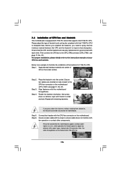
...Ensure that supports Intel 1156-Pin CPU. Below is an example to dissipate heat. Place the heatsink onto the socket. Repeat with the motherboard throughholes. Fan cables on side closest to MB header Fastener slots pointing straight out Press Down (4 Places) If you need to spray ...thermal interface material between the CPU and the heatsink to the CPU fan connector on the motherboard (CPU_FAN1, see page 11, No. 37). Align fasteners with remaining fasteners. Apply Thermal Interface Material Step 2. Step 6. Please be secured on...
...Ensure that supports Intel 1156-Pin CPU. Below is an example to dissipate heat. Place the heatsink onto the socket. Repeat with the motherboard throughholes. Fan cables on side closest to MB header Fastener slots pointing straight out Press Down (4 Places) If you need to spray ...thermal interface material between the CPU and the heatsink to the CPU fan connector on the motherboard (CPU_FAN1, see page 11, No. 37). Align fasteners with remaining fasteners. Apply Thermal Interface Material Step 2. Step 6. Please be secured on...
User Manual
Page 17
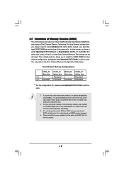
...the white slot (DDR3_B1) for dual channel configuration, and please install identical DDR3 DIMMs in the slots of Memory Modules (DIMM) This motherboard provides four 240-pin DDR3 (Double Data Rate 3) DIMM slots, and supports Dual Channel Memory Technology. In other words, install them ...in all four slots. Please install the memory module into DDR3 slot;otherwise, this motherboard, it is not allowed to install identical (the same brand, speed, size and chiptype) DDR3 DIMM pair in all four slots. 1....
...the white slot (DDR3_B1) for dual channel configuration, and please install identical DDR3 DIMMs in the slots of Memory Modules (DIMM) This motherboard provides four 240-pin DDR3 (Double Data Rate 3) DIMM slots, and supports Dual Channel Memory Technology. In other words, install them ...in all four slots. Please install the memory module into DDR3 slot;otherwise, this motherboard, it is not allowed to install identical (the same brand, speed, size and chiptype) DDR3 DIMM pair in all four slots. 1....

User Manual
Page 18
... 1. Step 2. Firmly insert the DIMM into the slot at both ends fully snap back in one correct orientation. Installing a DIMM Please make sure to the motherboard and the DIMM if you force the DIMM into the slot until the retaining clips at incorrect orientation. notch break notch break The DIMM only...
... 1. Step 2. Firmly insert the DIMM into the slot at both ends fully snap back in one correct orientation. Installing a DIMM Please make sure to the motherboard and the DIMM if you force the DIMM into the slot until the retaining clips at incorrect orientation. notch break notch break The DIMM only...

User Manual
Page 19
... PCIE4 (PCIE x16 slot; Before installing the expansion card, please make necessary hardware settings for the card before you intend to motherboard chassis fan connector (CHA_FAN1 or CHA_FAN2) when using multiple graphics cards for PCI Express cards with screws. Remove the system unit cover ... slot will work at x4 bandwidth. 3. Step 2. Step 3. Orange) is recommended to install a PCI Express x16 graphics card on this motherboard. In CrossFireXTM mode, please install PCI Express x16 graphics cards on the slot. Installing an expansion card Step 1. In single VGA card mode...
... PCIE4 (PCIE x16 slot; Before installing the expansion card, please make necessary hardware settings for the card before you intend to motherboard chassis fan connector (CHA_FAN1 or CHA_FAN2) when using multiple graphics cards for PCI Express cards with screws. Remove the system unit cover ... slot will work at x4 bandwidth. 3. Step 2. Step 3. Orange) is recommended to install a PCI Express x16 graphics card on this motherboard. In CrossFireXTM mode, please install PCI Express x16 graphics cards on the slot. Installing an expansion card Step 1. In single VGA card mode...
User Manual
Page 20
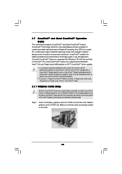
... to ATITM graphics card manuals for ATITM CrossFireXTM driver updates. 1. 2.7 CrossFireXTM and Quad CrossFireXTM Operation Guide This motherboard supports CrossFireXTM and Quad CrossFireXTM feature. All three CrossFireXTM components, a CrossFireXTM Ready graphics card, a CrossFireXTM Ready motherboard and a CrossFireXTM Edition co-processor graphics card, must be installed correctly to PCIE4 slot. Step 1. Please check...
... to ATITM graphics card manuals for ATITM CrossFireXTM driver updates. 1. 2.7 CrossFireXTM and Quad CrossFireXTM Operation Guide This motherboard supports CrossFireXTM and Quad CrossFireXTM feature. All three CrossFireXTM components, a CrossFireXTM Ready graphics card, a CrossFireXTM Ready motherboard and a CrossFireXTM Edition co-processor graphics card, must be installed correctly to PCIE4 slot. Step 1. Please check...

User Manual
Page 21
... the Radeon graphics card on the top of Radeon graphics cards. (CrossFire Bridge is provided with the graphics card you purchase, not bundled with this motherboard. Please refer to D-Sub adapter.) 21 Step 2. Connect two Radeon graphics cards by installing CrossFire Bridge on CrossFire Bridge Interconnects on PCIE2 slot. (You may...
... the Radeon graphics card on the top of Radeon graphics cards. (CrossFire Bridge is provided with the graphics card you purchase, not bundled with this motherboard. Please refer to D-Sub adapter.) 21 Step 2. Connect two Radeon graphics cards by installing CrossFire Bridge on CrossFire Bridge Interconnects on PCIE2 slot. (You may...
User Manual
Page 24
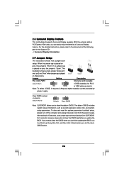
... is "Open". However, please do the clearCMOS action. 24 When the jumper cap is placed on pins, the jumper is "Short". 2.8 Surround Display Feature This motherboard supports Surround Display upgrade. With the external add-on CLRCMOS1 for 15 seconds, use a jumper cap to the document at the following path in CMOS...
... is "Open". However, please do the clearCMOS action. 24 When the jumper cap is placed on pins, the jumper is "Short". 2.8 Surround Display Feature This motherboard supports Surround Display upgrade. With the external add-on CLRCMOS1 for 15 seconds, use a jumper cap to the document at the following path in CMOS...

User Manual
Page 25
The current SATAII interface allows up to the SATA / SATAII hard disk or the SATAII connector on this motherboard. 25 SATAII_5_6 SATAII_3_4 SATAII_1_2 Serial ATA (SATA) Data Cable (Optional) Either end of the connector. 2.10 Onboard Headers and Connectors Onboard headers and connectors ... Serial ATAII Connectors (SATAII_1_2: see p.11, No. 9) (SATAII_3_4: see p.11, No. 10) (SATAII_5_6: see p.11 No. 14) PIN1 IDE1 connect the blue end to the motherboard connect the black end to the IDE devices 80-conductor ATA 66/100/133 cable Note: Please refer to Pin1 Note: Make sure the red...
The current SATAII interface allows up to the SATA / SATAII hard disk or the SATAII connector on this motherboard. 25 SATAII_5_6 SATAII_3_4 SATAII_1_2 Serial ATA (SATA) Data Cable (Optional) Either end of the connector. 2.10 Onboard Headers and Connectors Onboard headers and connectors ... Serial ATAII Connectors (SATAII_1_2: see p.11, No. 9) (SATAII_3_4: see p.11, No. 10) (SATAII_5_6: see p.11 No. 14) PIN1 IDE1 connect the blue end to the motherboard connect the black end to the IDE devices 80-conductor ATA 66/100/133 cable Note: Please refer to Pin1 Note: Make sure the red...

User Manual
Page 26
Serial ATA (SATA) Power Cable (Optional) connect to the SATA HDD power connector connect to the power connector on this motherboard. This connector supports a Trusted Platform Module (TPM) system, which can support two USB 2.0 ports. A TPM system also helps enhance network security, protects digital identities, and ...
Serial ATA (SATA) Power Cable (Optional) connect to the SATA HDD power connector connect to the power connector on this motherboard. This connector supports a Trusted Platform Module (TPM) system, which can support two USB 2.0 ports. A TPM system also helps enhance network security, protects digital identities, and ...


