RAID Installation Guide
Page 2
...Hard Disks Installation of "User Manual" in this motherboard for internal storage devices. Guide to create RAID on this guide carefully according to the Intel southbridge chipset that your motherboard adopts. You may install SATA hard disks on SATA ports. 2 Please read the RAID configurations in the support CD.... This section will guide you how to SATA Hard Disks Installation 1.1 Serial ATA (SATA) Hard Disks Installation Intel P55 southbridge chipset supports Serial ATA (SATA) hard disks with RAID functions, including RAID 0, RAID 1, RAID 10, RAID 5, and...
...Hard Disks Installation of "User Manual" in this motherboard for internal storage devices. Guide to create RAID on this guide carefully according to the Intel southbridge chipset that your motherboard adopts. You may install SATA hard disks on SATA ports. 2 Please read the RAID configurations in the support CD.... This section will guide you how to SATA Hard Disks Installation 1.1 Serial ATA (SATA) Hard Disks Installation Intel P55 southbridge chipset supports Serial ATA (SATA) hard disks with RAID functions, including RAID 0, RAID 1, RAID 10, RAID 5, and...

User Manual
Page 6
... EM64T CPU - Supports DDR3 2600+(OC)/2133(OC)/1866(OC)/1600/ 1333/1066 non-ECC, un-buffered memory - Max. Supports Intel® Extreme Memory Profile (XMP) (see CAUTION 2) - PCIE x1 Gigabit LAN 10/100/1000 Mb/s - DAC with Content Protection - 1.2... Level HD Audio with 110dB dynamic range (ALC890 Audio Codec) - Supports Intel® Turbo Boost Technology - Dual Channel DDR3 Memory Technology (see CAUTION 1) - Supports Hyper-Threading Technology (see CAUTION 3) - 4 x DDR3 DIMM slots - Intel® P55 - capacity of system memory: 16GB (see CAUTION 4) - Premium Blu-ray...
... EM64T CPU - Supports DDR3 2600+(OC)/2133(OC)/1866(OC)/1600/ 1333/1066 non-ECC, un-buffered memory - Max. Supports Intel® Extreme Memory Profile (XMP) (see CAUTION 2) - PCIE x1 Gigabit LAN 10/100/1000 Mb/s - DAC with Content Protection - 1.2... Level HD Audio with 110dB dynamic range (ALC890 Audio Codec) - Supports Intel® Turbo Boost Technology - Dual Channel DDR3 Memory Technology (see CAUTION 1) - Supports Hyper-Threading Technology (see CAUTION 3) - 4 x DDR3 DIMM slots - Intel® P55 - capacity of system memory: 16GB (see CAUTION 4) - Premium Blu-ray...

User Manual
Page 12
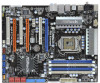
... LINE IN Center: FRONT Bottom: MIC IN 40 LAN PHY CPU_FAN1 P55 Extreme 39 PCIE1 38 PCI1 VIA VT6330 16Mb BIOS 37 CMOS CrossFireX Battery PCIE2 36 1394a Intel Super I/O PCIE3 PCI Express 2.0 P55 IDE1 35 PCI2 SATAII_5_6 SATAII_3_4 SATAII_1_2 34 33 32 AUDIO CODEC CD1 ...1 PS2_USB_PWR1 Jumper 22 Dr. Debug (LED) 2 ATX 12V Power Connector (ATX12V1) 23 USB 2.0 Header (USB8_9, Blue) 3 1156-Pin CPU Socket 24 Intel P55 Chipset 4 Chassis Fan Connector (CHA_FAN3) 25 Front Panel IEEE 1394 Header 5 2 x 240-pin DDR3 DIMM Slots (FRONT_1394, Red) (Dual Channel: DDR3_A2,...
... LINE IN Center: FRONT Bottom: MIC IN 40 LAN PHY CPU_FAN1 P55 Extreme 39 PCIE1 38 PCI1 VIA VT6330 16Mb BIOS 37 CMOS CrossFireX Battery PCIE2 36 1394a Intel Super I/O PCIE3 PCI Express 2.0 P55 IDE1 35 PCI2 SATAII_5_6 SATAII_3_4 SATAII_1_2 34 33 32 AUDIO CODEC CD1 ...1 PS2_USB_PWR1 Jumper 22 Dr. Debug (LED) 2 ATX 12V Power Connector (ATX12V1) 23 USB 2.0 Header (USB8_9, Blue) 3 1156-Pin CPU Socket 24 Intel P55 Chipset 4 Chassis Fan Connector (CHA_FAN3) 25 Front Panel IEEE 1394 Header 5 2 x 240-pin DDR3 DIMM Slots (FRONT_1394, Red) (Dual Channel: DDR3_A2,...

User Manual
Page 43
... you plan to use RAID 5 function, you need to install the SATA / SATAII hard disks. If you plan to use RAID 0, RAID 1, RAID 10 or Intel Matrix Storage function, you to install at least 3 SATA / SATAII hard disks. 2. STEP 1: Install the SATA / SATAII hard disks into the drive bays of... SATA / SATAII hard disks on this motherboard for internal storage devices. 2.16 Serial ATA (SATA) / Serial ATAII (SATAII) Hard Disks Installation This motherboard adopts Intel® P55 chipset that supports Serial ATA (SATA) / Serial ATAII (SATAII) hard disks and RAID (RAID 0, RAID 1, RAID 10, RAID 5, and...
... you plan to use RAID 5 function, you need to install the SATA / SATAII hard disks. If you plan to use RAID 0, RAID 1, RAID 10 or Intel Matrix Storage function, you to install at least 3 SATA / SATAII hard disks. 2. STEP 1: Install the SATA / SATAII hard disks into the drive bays of... SATA / SATAII hard disks on this motherboard for internal storage devices. 2.16 Serial ATA (SATA) / Serial ATAII (SATAII) Hard Disks Installation This motherboard adopts Intel® P55 chipset that supports Serial ATA (SATA) / Serial ATAII (SATAII) hard disks and RAID (RAID 0, RAID 1, RAID 10, RAID 5, and...

User Manual
Page 44
... / SATAII HDDs are built as RAID1 or RAID 5 then it cannot perform Hot Plug if the OS has been installed into the SATA / SATAII HDD. Intel® P55 chipset provides hardware support for Advanced Host controller Interface (AHCI), a new programming interface for SATA host controllers developed thru a joint industry effort. 2.17 Hot...
... / SATAII HDDs are built as RAID1 or RAID 5 then it cannot perform Hot Plug if the OS has been installed into the SATA / SATAII HDD. Intel® P55 chipset provides hardware support for Advanced Host controller Interface (AHCI), a new programming interface for SATA host controllers developed thru a joint industry effort. 2.17 Hot...

User Manual
Page 55
... Main OC Tweaker Advanced H/W Monitor Boot Security Exit System Overview System Time System Date [14:00:09] [Thu 06/04/2009] BIOS Version : P55 Extreme P1.00 Processor Type : Intel (R) Core (TM) CPU 860 @ 2.80GHz (64bit) Processor Speed : 2800MHz Microcode Update : 106E5/3 Cache Size : 8192KB Total Memory DDR3_A2 DDR3_A1 DDR3_B2 DDR3_B1 : 2048MB Single...
... Main OC Tweaker Advanced H/W Monitor Boot Security Exit System Overview System Time System Date [14:00:09] [Thu 06/04/2009] BIOS Version : P55 Extreme P1.00 Processor Type : Intel (R) Core (TM) CPU 860 @ 2.80GHz (64bit) Processor Speed : 2800MHz Microcode Update : 106E5/3 Cache Size : 8192KB Total Memory DDR3_A2 DDR3_A1 DDR3_B2 DDR3_B1 : 2048MB Single...

Quick Installation Guide
Page 2
Motherboard Layout English 1 PS2_USB_PWR1 Jumper 22 Dr. Debug (LED) 2 ATX 12V Power Connector (ATX12V1) 23 USB 2.0 Header (USB8_9, Blue) 3 1156-Pin CPU Socket 24 Intel P55 Chipset 4 Chassis Fan Connector (CHA_FAN3) 25 Front Panel IEEE 1394 Header 5 2 x 240-pin DDR3 DIMM Slots (FRONT_1394, Red) (Dual Channel: DDR3_A2, DDR3_B2, Blue) 26 Chassis ... Express 2.0 x16 Slot (PCIE1, Blue) 20 Infrared Module Header (IR1) 40 CPU Fan Connector (CPU_FAN1) 21 USB 2.0 Header (USB10_11, Blue) 41 Power Fan Connector (PWR_FAN1) 2 ASRock P55 Extreme Motherboard
Motherboard Layout English 1 PS2_USB_PWR1 Jumper 22 Dr. Debug (LED) 2 ATX 12V Power Connector (ATX12V1) 23 USB 2.0 Header (USB8_9, Blue) 3 1156-Pin CPU Socket 24 Intel P55 Chipset 4 Chassis Fan Connector (CHA_FAN3) 25 Front Panel IEEE 1394 Header 5 2 x 240-pin DDR3 DIMM Slots (FRONT_1394, Red) (Dual Channel: DDR3_A2, DDR3_B2, Blue) 26 Chassis ... Express 2.0 x16 Slot (PCIE1, Blue) 20 Infrared Module Header (IR1) 40 CPU Fan Connector (CPU_FAN1) 21 USB 2.0 Header (USB10_11, Blue) 41 Power Fan Connector (PWR_FAN1) 2 ASRock P55 Extreme Motherboard

Quick Installation Guide
Page 5
... Port - 1 x PS/2 Keyboard Port - 1 x Coaxial SPDIF Out Port - 1 x Optical SPDIF Out Port - 7 x Ready-to-Use USB 2.0 Ports 5 ASRock P55 Extreme Motherboard English Realtek RTL8111DL - Advanced V8 + 2 Power Phase Design - Supports EM64T CPU - Supports the Intel® CoreTM i7 and Intel® CoreTM i5 Processors in , 30.5 cm x 24.4 cm - Supports Hyper-Threading Technology (see CAUTION 1) -
... Port - 1 x PS/2 Keyboard Port - 1 x Coaxial SPDIF Out Port - 1 x Optical SPDIF Out Port - 7 x Ready-to-Use USB 2.0 Ports 5 ASRock P55 Extreme Motherboard English Realtek RTL8111DL - Advanced V8 + 2 Power Phase Design - Supports EM64T CPU - Supports the Intel® CoreTM i7 and Intel® CoreTM i5 Processors in , 30.5 cm x 24.4 cm - Supports Hyper-Threading Technology (see CAUTION 1) -

Quick Installation Guide
Page 6
... LED) Smart Switch - 1 x Clear CMOS Switch with LED - 1 x Power Switch with LED - 1 x Reset Switch with LED - Supports Smart BIOS Support CD - Hybrid Booster: 6 ASRock P55 Extreme Motherboard Supports "Plug and Play" - Supports I. Intelligent Energy Saver (see CAUTION 7) - 1 x ATA133 IDE connector (supports 2 x IDE devices) - 1 x Floppy connector - 1 x IR...Front Speaker/Microphone (see CAUTION 6) Connector - 6 x SATAII 3.0Gb/s connectors, support RAID (RAID 0, RAID 1, RAID 10, RAID 5 and Intel Matrix Storage), NCQ, AHCI and "Hot Plug" functions (see CAUTION 10) -
... LED) Smart Switch - 1 x Clear CMOS Switch with LED - 1 x Power Switch with LED - 1 x Reset Switch with LED - Supports Smart BIOS Support CD - Hybrid Booster: 6 ASRock P55 Extreme Motherboard Supports "Plug and Play" - Supports I. Intelligent Energy Saver (see CAUTION 7) - 1 x ATA133 IDE connector (supports 2 x IDE devices) - 1 x Floppy connector - 1 x IR...Front Speaker/Microphone (see CAUTION 6) Connector - 6 x SATAII 3.0Gb/s connectors, support RAID (RAID 0, RAID 1, RAID 10, RAID 5 and Intel Matrix Storage), NCQ, AHCI and "Hot Plug" functions (see CAUTION 10) -

Quick Installation Guide
Page 9
Intel's suggestion, the EuP ready power supply must meet the standard of 5v standby power efficiency is supported under 100 mA current consumption. ASRock website: http://www.asrock.com/support/index.htm English 9 ASRock P55 Extreme Motherboard For EuP ready power supply selection, we recommend you checking with the power supply manufacturer for more details. 1.3 Two SLITM...
Intel's suggestion, the EuP ready power supply must meet the standard of 5v standby power efficiency is supported under 100 mA current consumption. ASRock website: http://www.asrock.com/support/index.htm English 9 ASRock P55 Extreme Motherboard For EuP ready power supply selection, we recommend you checking with the power supply manufacturer for more details. 1.3 Two SLITM...

Quick Installation Guide
Page 11
...wrist strap or touch a safety grounded object before touching any bent pin on the carpet or the like. English 11 ASRock P55 Extreme Motherboard Unplug the power cord from the wall socket before you insert the 1156-Pin CPU into the socket if above ...00PRO Catalyst 9.1 00XT Catalyst 9.1 0X2 Catalyst 9.1 350 Catalyst 9.1 870X2 Catalyst 9.1 Catalyst 9.6 Catalyst 9.6 2. Installation Pre-installation Precautions Take note of Intel 1156-Pin CPU, please follow the steps below. 1156-Pin Socket Overview Before you handle components. 3. Do not force to the motherboard, peripherals,...
...wrist strap or touch a safety grounded object before touching any bent pin on the carpet or the like. English 11 ASRock P55 Extreme Motherboard Unplug the power cord from the wall socket before you insert the 1156-Pin CPU into the socket if above ...00PRO Catalyst 9.1 00XT Catalyst 9.1 0X2 Catalyst 9.1 350 Catalyst 9.1 870X2 Catalyst 9.1 Catalyst 9.6 Catalyst 9.6 2. Installation Pre-installation Precautions Take note of Intel 1156-Pin CPU, please follow the steps below. 1156-Pin Socket Overview Before you handle components. 3. Do not force to the motherboard, peripherals,...

Quick Installation Guide
Page 35
...HDDs without RAID functions, please follow the instruction to install Windows® VistaTM / VistaTM 64-bit OS on the bottom to load the Intel® AHCI drivers. Set the option "SATAII Operation Mode" to [AHCI]. When you see "Where do you want to install Windows...into the optical drive to boot your system, and follow below steps. page, please insert the ASRock Support CD into the optical drive again to continue the installation. 35 ASRock P55 Extreme Motherboard English Enter BIOS SETUP UTILITY Advanced screen Storage Configuration. B. Enter BIOS SETUP UTILITY Advanced ...
...HDDs without RAID functions, please follow the instruction to install Windows® VistaTM / VistaTM 64-bit OS on the bottom to load the Intel® AHCI drivers. Set the option "SATAII Operation Mode" to [AHCI]. When you see "Where do you want to install Windows...into the optical drive to boot your system, and follow below steps. page, please insert the ASRock Support CD into the optical drive again to continue the installation. 35 ASRock P55 Extreme Motherboard English Enter BIOS SETUP UTILITY Advanced screen Storage Configuration. B. Enter BIOS SETUP UTILITY Advanced ...


