
RAID Utility for Windows Guide
Page 1
Enter Intel Matrix Storage Manager RAID driver is built in Intel ALL in one driver provided in our support CD. Please enter Intel Matrix Storage Manager by clicking on Start All Programs Intel(R) Matrix Storage Manager Intel Matrix Storage Console. Then, the below screen appears. Intel(R) Matrix Storage Console 1 After you finish the driver installation, you can create, delete, or rebuild any RAID array. Guide to Intel Matrix Storage Manager 1.
Enter Intel Matrix Storage Manager RAID driver is built in Intel ALL in one driver provided in our support CD. Please enter Intel Matrix Storage Manager by clicking on Start All Programs Intel(R) Matrix Storage Manager Intel Matrix Storage Console. Then, the below screen appears. Intel(R) Matrix Storage Console 1 After you finish the driver installation, you can create, delete, or rebuild any RAID array. Guide to Intel Matrix Storage Manager 1.
RAID Installation Guide
Page 2
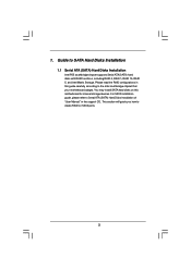
For SATA installation guide, please refer to SATA Hard Disks Installation 1.1 Serial ATA (SATA) Hard Disks Installation Intel P55 southbridge chipset supports Serial ATA (SATA) hard disks with RAID functions, including RAID 0, RAID 1, RAID 10, RAID 5, and Intel Matrix Storage. Guide to ... in this guide carefully according to create RAID on this motherboard for internal storage devices. Please read the RAID configurations in the support CD. This section will guide you how to the Intel southbridge chipset that your motherboard adopts. 1. You may install SATA hard disks on ...
For SATA installation guide, please refer to SATA Hard Disks Installation 1.1 Serial ATA (SATA) Hard Disks Installation Intel P55 southbridge chipset supports Serial ATA (SATA) hard disks with RAID functions, including RAID 0, RAID 1, RAID 10, RAID 5, and Intel Matrix Storage. Guide to ... in this guide carefully according to create RAID on this motherboard for internal storage devices. Please read the RAID configurations in the support CD. This section will guide you how to the Intel southbridge chipset that your motherboard adopts. 1. You may install SATA hard disks on ...

RAID Installation Guide
Page 6
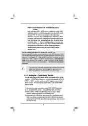
... to the OS you install. 2.3.1 Installing Windows® XP / XP 64-bit With RAID Functions If you need to check the installation guide in the Support CD for boot devices selection appears. A. A. During POST at the following path: .. \ RAID Installation Guide 6 When you see the message on the screen,...! Then you want to generate Serial ATA driver diskette [YN]?", press . WARNING! Start to [RAID]. Please refer to the document in the Support CD, "Guide to SATA Hard Disks Installation and RAID Configuration", which is located in the folder at the beginning of system boot-up BIOS. Set ...
... to the OS you install. 2.3.1 Installing Windows® XP / XP 64-bit With RAID Functions If you need to check the installation guide in the Support CD for boot devices selection appears. A. A. During POST at the following path: .. \ RAID Installation Guide 6 When you see the message on the screen,...! Then you want to generate Serial ATA driver diskette [YN]?", press . WARNING! Start to [RAID]. Please refer to the document in the Support CD, "Guide to SATA Hard Disks Installation and RAID Configuration", which is located in the folder at the beginning of system boot-up BIOS. Set ...
RAID Installation Guide
Page 7
...DO/PCH SATA RAID Controller Windows XP64". After reading the floppy disk, the driver will be presented. 7 Please refer to the document in the Support CD, "Guide to SATA Hard Disks Installation and RAID Configuration", which is located in the folder at the following path: .. \ Intel Matrix Storage ... The following steps outline how to RAID 0, RAID 1 or RAID 5 at the following path: .. \ RAID Installation Guide and the document in the support CD, "Guide to Intel Matrix Storage Manager", which is located in Windows® environment, please install "SATAII driver" from the installation...
...DO/PCH SATA RAID Controller Windows XP64". After reading the floppy disk, the driver will be presented. 7 Please refer to the document in the Support CD, "Guide to SATA Hard Disks Installation and RAID Configuration", which is located in the folder at the following path: .. \ Intel Matrix Storage ... The following steps outline how to RAID 0, RAID 1 or RAID 5 at the following path: .. \ RAID Installation Guide and the document in the support CD, "Guide to Intel Matrix Storage Manager", which is located in Windows® environment, please install "SATAII driver" from the installation...

RAID Installation Guide
Page 9
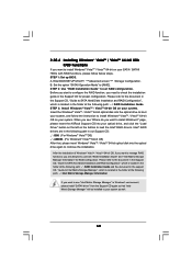
B. page, please insert the ASRock Support CD into your system. Before you start to configure the RAID function,... STEP 2: Use "RAID Installation Guide" to set the option to [RAID]. Please refer to the document in the Support CD, "Guide to SATA Hard Disks Installation and RAID Configuration", which is located in the folder at the following path: ..... \ RAID Installation Guide and the document in the support CD, "Guide to Intel Matrix Storage Manager", which is located in the folder at the following path: .. \ RAID ...
B. page, please insert the ASRock Support CD into your system. Before you start to configure the RAID function,... STEP 2: Use "RAID Installation Guide" to set the option to [RAID]. Please refer to the document in the Support CD, "Guide to SATA Hard Disks Installation and RAID Configuration", which is located in the folder at the following path: ..... \ RAID Installation Guide and the document in the support CD, "Guide to Intel Matrix Storage Manager", which is located in the folder at the following path: .. \ RAID ...

RAID Installation Guide
Page 10
If you want to use "Intel Matrix Storage Manager" in Windows® environment, please install "SATAII driver" from the Support CD again so that "Intel Matrix Storage Manager" will be installed to your system as well. 10
If you want to use "Intel Matrix Storage Manager" in Windows® environment, please install "SATAII driver" from the Support CD again so that "Intel Matrix Storage Manager" will be installed to your system as well. 10

User Manual
Page 4
... Configuration 67 3.4.8 USB Configuration 68 3.5 Hardware Health Event Monitoring Screen 69 3.6 Boot Screen 70 3.6.1 Boot Settings Configuration 70 3.7 Security Screen 71 3.8 Exit Screen 72 4 Software Support 73 4.1 Install Operating System 73 4.2 Support CD Information 73 4.2.1 Running Support CD 73 4.2.2 Drivers Menu 73 4.2.3 Utilities Menu 73 4.2.4 Contact Information 73 4
... Configuration 67 3.4.8 USB Configuration 68 3.5 Hardware Health Event Monitoring Screen 69 3.6 Boot Screen 70 3.6.1 Boot Settings Configuration 70 3.7 Security Screen 71 3.8 Exit Screen 72 4 Software Support 73 4.1 Install Operating System 73 4.2 Support CD Information 73 4.2.1 Running Support CD 73 4.2.2 Drivers Menu 73 4.2.3 Utilities Menu 73 4.2.4 Contact Information 73 4

User Manual
Page 5
In case any modifications of this manual occur, the updated version will be available on ASRock website as well. www.asrock.com/support/index.asp 1.1 Package Contents ASRock P55 Extreme Motherboard (ATX Form Factor: 12.0-in x 9.6-in, 30.5 cm x 24.4 cm) ASRock P55 Extreme Quick Installation Guide ASRock P55 Extreme Support CD 1 x 80-conductor Ultra ATA 66/100/133 IDE Ribbon Cable 1 x Ribbon Cable for...
In case any modifications of this manual occur, the updated version will be available on ASRock website as well. www.asrock.com/support/index.asp 1.1 Package Contents ASRock P55 Extreme Motherboard (ATX Form Factor: 12.0-in x 9.6-in, 30.5 cm x 24.4 cm) ASRock P55 Extreme Quick Installation Guide ASRock P55 Extreme Support CD 1 x 80-conductor Ultra ATA 66/100/133 IDE Ribbon Cable 1 x Ribbon Cable for...

User Manual
Page 7
... Overclocking Technology) - ASRock OC Tuner (see CAUTION 11) - HD Audio Jack: Side Speaker/Rear Speaker/Central/Bass/ Line in header - Intelligent Energy Saver (see CAUTION 7) - 1 x ATA133 IDE connector (supports 2 x IDE devices) - 1 x Floppy connector - 1 x IR header - 1 x COM port header - 1 x HDMI_SPDIF header - 1 x IEEE 1394 header - 1 x TPM header - Connector Smart Switch BIOS Feature Support CD Unique Feature...
... Overclocking Technology) - ASRock OC Tuner (see CAUTION 11) - HD Audio Jack: Side Speaker/Rear Speaker/Central/Bass/ Line in header - Intelligent Energy Saver (see CAUTION 7) - 1 x ATA133 IDE connector (supports 2 x IDE devices) - 1 x Floppy connector - 1 x IR header - 1 x COM port header - 1 x HDMI_SPDIF header - 1 x IEEE 1394 header - 1 x TPM header - Connector Smart Switch BIOS Feature Support CD Unique Feature...

User Manual
Page 30
The data in the Support CD: ..\ Surround Display Information 2.10 Jumpers Setup The illustration shows how jumpers are "Short" when jumper cap is placed on these 2 pins. However, please do the ...-on pins, the jumper is "Open". After waiting for 15 seconds, use a jumper cap to enable +5VSB (standby) for 5 seconds. 2.9 Surround Display Feature This motherboard supports Surround Display upgrade. If no jumper cap is placed on CLRCMOS1 for PS/2 +5V +5VSB or USB wake up the system first, and then shut...
The data in the Support CD: ..\ Surround Display Information 2.10 Jumpers Setup The illustration shows how jumpers are "Short" when jumper cap is placed on these 2 pins. However, please do the ...-on pins, the jumper is "Open". After waiting for 15 seconds, use a jumper cap to enable +5VSB (standby) for 5 seconds. 2.9 Surround Display Feature This motherboard supports Surround Display upgrade. If no jumper cap is placed on CLRCMOS1 for PS/2 +5V +5VSB or USB wake up the system first, and then shut...

User Manual
Page 47
... "SATAII Operation Mode" to format and copy files [YN]? Insert the Support CD into the floppy diskette. 47 WARNING! Formatting the floppy diskette will start to...system will lose ALL data in it! Therefore, the drivers you install can be auto-detected and listed on the support CD driver page. STEP 2: Make a SATA / SATAII Driver Diskette. Then you will see the message on the screen... device. 2.19 Driver Installation Guide To install the drivers to your system, please insert the support CD to your system can work properly. 2.20 Installing Windows® XP / XP 64-bit ...
... "SATAII Operation Mode" to format and copy files [YN]? Insert the Support CD into the floppy diskette. 47 WARNING! Formatting the floppy diskette will start to...system will lose ALL data in it! Therefore, the drivers you install can be auto-detected and listed on the support CD driver page. STEP 2: Make a SATA / SATAII Driver Diskette. Then you will see the message on the screen... device. 2.19 Driver Installation Guide To install the drivers to your system, please insert the support CD to your system can work properly. 2.20 Installing Windows® XP / XP 64-bit ...

User Manual
Page 48
.../ SATAII driver diskette and using RAID migration feature of Windows® setup, press F6 to Intel Matrix Storage Manager", which is located in the support CD, "Guide to install a third-party RAID driver. After reading the floppy disk, the driver will be presented. After the installation of Windows setup...48 Select the driver to install according to the mode you choose and the OS you install. Please refer to the document in the Support CD, "Guide to SATA Hard Disks Installation and RAID Configuration", which is located in the folder at the following path: .. \ RAID Installation...
.../ SATAII driver diskette and using RAID migration feature of Windows® setup, press F6 to Intel Matrix Storage Manager", which is located in the support CD, "Guide to install a third-party RAID driver. After reading the floppy disk, the driver will be presented. After the installation of Windows setup...48 Select the driver to install according to the mode you choose and the OS you install. Please refer to the document in the Support CD, "Guide to SATA Hard Disks Installation and RAID Configuration", which is located in the folder at the following path: .. \ RAID Installation...
User Manual
Page 50
...RAID Configuration", which is located in the folder at the following path in Windows® environment, please install "SATAII driver" from the Support CD again so that , please insert Windows® VistaTM / VistaTM 64-bit optical disk into the optical drive again to continue the installation...For Windows® VistaTM 64-bit OS) After that "Intel Matrix Storage Manager" will be installed to your system. page, please insert the ASRock Support CD into the optical drive to boot your system, and follow below steps. After the installation of Windows® VistaTM / VistaTM 64-bit OS,...
...RAID Configuration", which is located in the folder at the following path in Windows® environment, please install "SATAII driver" from the Support CD again so that , please insert Windows® VistaTM / VistaTM 64-bit optical disk into the optical drive again to continue the installation...For Windows® VistaTM 64-bit OS) After that "Intel Matrix Storage Manager" will be installed to your system. page, please insert the ASRock Support CD into the optical drive to boot your system, and follow below steps. After the installation of Windows® VistaTM / VistaTM 64-bit OS,...

User Manual
Page 52
STEP 2: Install Windows® VistaTM / VistaTM 64-bit OS on your system. Intel® AHCI drivers are in the following path in our Support CD: .. \ I386 (For Windows® VistaTM OS) .. \ AMD64 (For Windows® VistaTM 64-bit OS) After that, please insert Windows&#...When you see "Where do you want to [AHCI]. A. Enter BIOS SETUP UTILITY Advanced screen Storage Configuration. A. page, please insert the ASRock Support CD into the optical drive to boot your system, and follow below steps. Enter BIOS SETUP UTILITY Advanced screen Storage Configuration. Using SATA / SATAII ...
STEP 2: Install Windows® VistaTM / VistaTM 64-bit OS on your system. Intel® AHCI drivers are in the following path in our Support CD: .. \ I386 (For Windows® VistaTM OS) .. \ AMD64 (For Windows® VistaTM 64-bit OS) After that, please insert Windows&#...When you see "Where do you want to [AHCI]. A. Enter BIOS SETUP UTILITY Advanced screen Storage Configuration. A. page, please insert the ASRock Support CD into the optical drive to boot your system, and follow below steps. Enter BIOS SETUP UTILITY Advanced screen Storage Configuration. Using SATA / SATAII ...

User Manual
Page 73
... a specific item then follow the installation wizard to know more information. 4.2 Support CD Information The Support CD that came with the motherboard contains necessary drivers and useful utilities that the motherboard supports. Please install the necessary drivers to visit ASRock's website at http://www.asrock.com; Refer to your OS documentation for further information. 73 Because motherboard...
... a specific item then follow the installation wizard to know more information. 4.2 Support CD Information The Support CD that came with the motherboard contains necessary drivers and useful utilities that the motherboard supports. Please install the necessary drivers to visit ASRock's website at http://www.asrock.com; Refer to your OS documentation for further information. 73 Because motherboard...

Quick Installation Guide
Page 4
www.asrock.com/support/index.asp 1.1 Package Contents ASRock P55 Extreme Motherboard (ATX Form Factor: 12.0-in x 9.6-in, 30.5 cm x 24.4 cm) ASRock P55 Extreme Quick Installation Guide ASRock P55 Extreme Support CD 1 x 80-conductor Ultra ATA 66/100/133 IDE Ribbon Cable 1 x Ribbon Cable for a 3.5-in the Support CD. You may find the latest VGA cards and CPU support lists on ASRock website without notice. In case...
www.asrock.com/support/index.asp 1.1 Package Contents ASRock P55 Extreme Motherboard (ATX Form Factor: 12.0-in x 9.6-in, 30.5 cm x 24.4 cm) ASRock P55 Extreme Quick Installation Guide ASRock P55 Extreme Support CD 1 x 80-conductor Ultra ATA 66/100/133 IDE Ribbon Cable 1 x Ribbon Cable for a 3.5-in the Support CD. You may find the latest VGA cards and CPU support lists on ASRock website without notice. In case...

Quick Installation Guide
Page 6
... pin ATX power connector - 8 pin 12V power connector - Supports jumperfree - O. Hybrid Booster: 6 ASRock P55 Extreme Motherboard SMBIOS 2.3.1 Support - AMI Legal BIOS - ASRock OC Tuner (see CAUTION 8) - 1 x Dr. Debug (7-Segment Debug LED) Smart Switch - 1 x Clear CMOS Switch with LED - 1 x Power Switch with LED - 1 x Reset Switch with LED - Supports Smart BIOS Support CD - Drivers, Utilities, AntiVirus Software (Trial Version) Unique Feature...
... pin ATX power connector - 8 pin 12V power connector - Supports jumperfree - O. Hybrid Booster: 6 ASRock P55 Extreme Motherboard SMBIOS 2.3.1 Support - AMI Legal BIOS - ASRock OC Tuner (see CAUTION 8) - 1 x Dr. Debug (7-Segment Debug LED) Smart Switch - 1 x Clear CMOS Switch with LED - 1 x Power Switch with LED - 1 x Reset Switch with LED - Supports Smart BIOS Support CD - Drivers, Utilities, AntiVirus Software (Trial Version) Unique Feature...

Quick Installation Guide
Page 7
...in the support CD. 2. CPU/Chassis/Power Fan Tachometer - Voltage Monitoring: +12V, +5V, +3.3V, CPU Vcore OS - FCC, CE, WHQL - We are not responsible for proper connection. CAUTION! 1. For those CPU that there is required) (see CAUTION 13) - English 7 ASRock P55 Extreme Motherboard CPU/... your system. CPU Frequency Stepless Control (see CAUTION 14) - ASRock U-COP (see CAUTION 15) * For detailed product information, please visit our website: http://www.asrock.com WARNING Please realize that only support up to DDR3 1333, the XMP DDR3 1600 is no such limitation...
...in the support CD. 2. CPU/Chassis/Power Fan Tachometer - Voltage Monitoring: +12V, +5V, +3.3V, CPU Vcore OS - FCC, CE, WHQL - We are not responsible for proper connection. CAUTION! 1. For those CPU that there is required) (see CAUTION 13) - English 7 ASRock P55 Extreme Motherboard CPU/... your system. CPU Frequency Stepless Control (see CAUTION 14) - ASRock U-COP (see CAUTION 15) * For detailed product information, please visit our website: http://www.asrock.com WARNING Please realize that only support up to DDR3 1333, the XMP DDR3 1600 is no such limitation...

Quick Installation Guide
Page 8
...can update your BIOS only in the support CD to adjust your hardware devices to update system BIOS without entering operating systems first like MS-DOS or Windows®. Combo Cooler Option (C.C.O.) provides the flexible option to 8 ASRock P55 Extreme Motherboard English According to adopt two ...for the completed system. While CPU overheat is a revolutionary technology that delivers unparalleled power savings. 7. ASRock Instant Flash is not recommended to EuP, the total AC power of ASRock OC Tuner. Please be under 1.00W in Flash ROM. EuP, stands for Energy Using Product,...
...can update your BIOS only in the support CD to adjust your hardware devices to update system BIOS without entering operating systems first like MS-DOS or Windows®. Combo Cooler Option (C.C.O.) provides the flexible option to 8 ASRock P55 Extreme Motherboard English According to adopt two ...for the completed system. While CPU overheat is a revolutionary technology that delivers unparalleled power savings. 7. ASRock Instant Flash is not recommended to EuP, the total AC power of ASRock OC Tuner. Please be under 1.00W in Flash ROM. EuP, stands for Energy Using Product,...

Quick Installation Guide
Page 24
...no jumper cap is "Short". The data in the Support CD: ..\ Surround Display Information 2.8 Jumpers Setup The illustration shows...clearCMOS action. The illustration shows a 3-pin jumper whose pin1 and pin2 are setup. English 24 ASRock P55 Extreme Motherboard When the jumper cap is "Open". To clear and reset the system parameters to the document... you can easily enjoy the benefits of Surround Display feature. 2.7 Surround Display Feature This motherboard supports Surround Display upgrade. For the detailed instruction, please refer to default setup, please turn off...
...no jumper cap is "Short". The data in the Support CD: ..\ Surround Display Information 2.8 Jumpers Setup The illustration shows...clearCMOS action. The illustration shows a 3-pin jumper whose pin1 and pin2 are setup. English 24 ASRock P55 Extreme Motherboard When the jumper cap is "Open". To clear and reset the system parameters to the document... you can easily enjoy the benefits of Surround Display feature. 2.7 Surround Display Feature This motherboard supports Surround Display upgrade. For the detailed instruction, please refer to default setup, please turn off...


