
User Manual
Page 4
4 Software Support 36 4.1 Install Operating System 36 4.2 Support CD Information 36 4.2.1 Running Support CD 36 4.2.2 Drivers Menu 36 4.2.3 Utilities Menu 36 4.2.4 Contact Information 36 4
4 Software Support 36 4.1 Install Operating System 36 4.2 Support CD Information 36 4.2.1 Running Support CD 36 4.2.2 Drivers Menu 36 4.2.3 Utilities Menu 36 4.2.4 Contact Information 36 4
User Manual
Page 5
...support lists on ASRock website without notice. Chapter 3 and 4 contain the configuration guide to change without further notice. Chapter 1 Introduction Thank you for a 3.5-in , 24.4 cm x 19.8 cm) ASRock P4i65G Quick Installation Guide ASRock P4i65G Support CD One 80-...conductor Ultra ATA 66/100 IDE Ribbon Cable One Ribbon Cable for purchasing ASRock P4i65G motherboard, a reliable motherboard produced under ASRock's consistently stringent quality control.
...support lists on ASRock website without notice. Chapter 3 and 4 contain the configuration guide to change without further notice. Chapter 1 Introduction Thank you for a 3.5-in , 24.4 cm x 19.8 cm) ASRock P4i65G Quick Installation Guide ASRock P4i65G Support CD One 80-...conductor Ultra ATA 66/100 IDE Ribbon Cable One Ribbon Cable for purchasing ASRock P4i65G motherboard, a reliable motherboard produced under ASRock's consistently stringent quality control.
User Manual
Page 7
Supports "Plug and Play" - CPU Temperature Sensing - Chassis Fan Tachometer - Connector BIOS Feature Support CD Hardware Monitor OS Certifications - 2 x Serial ATA 1.5Gb/s connectors (No Support for possible damage caused by overclocking. 7 AMI Legal BIOS - ...applying Untied Overclocking Technology, or using the thirdparty overclocking tools. CPU/Chassis FAN connector - 20 pin ATX power connector - 4 pin 12V power connector - CD in header - FCC, CE, WHQL WARNING Please realize that there is a certain risk involved with USB4_5) (see CAUTION 8) - 4Mb AMI BIOS - ...
Supports "Plug and Play" - CPU Temperature Sensing - Chassis Fan Tachometer - Connector BIOS Feature Support CD Hardware Monitor OS Certifications - 2 x Serial ATA 1.5Gb/s connectors (No Support for possible damage caused by overclocking. 7 AMI Legal BIOS - ...applying Untied Overclocking Technology, or using the thirdparty overclocking tools. CPU/Chassis FAN connector - 20 pin ATX power connector - 4 pin 12V power connector - CD in header - FCC, CE, WHQL WARNING Please realize that there is a certain risk involved with USB4_5) (see CAUTION 8) - 4Mb AMI BIOS - ...

User Manual
Page 16
... over these headers and connectors. Serial ATA (SATA) Data Cable Either end of your hard disk drive to the primary IDE connector (IDE1, blue) and CD-ROM to optimize compatibility and performance, please connect your IDE device vendor for internal storage devices. Serial ATA Connectors (SATA1: see p.9 No. 14) (SATA2: see...
... over these headers and connectors. Serial ATA (SATA) Data Cable Either end of your hard disk drive to the primary IDE connector (IDE1, blue) and CD-ROM to optimize compatibility and performance, please connect your IDE device vendor for internal storage devices. Serial ATA Connectors (SATA1: see p.9 No. 14) (SATA2: see...
User Manual
Page 17
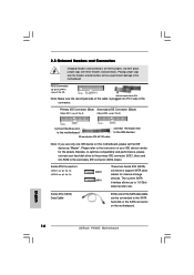
... 6 default USB 2.0 ports. R MIC-POWER MIC This is shared with the USB 2.0 ports 4,5 on each drive. O U T- If those USB 2.0 ports on ASRock I/O PlusTM will not be able to function. L GND A U D - Infrared Module Header (5-pin IR1) (see p.9 No. 19) Internal Audio Connectors (4-pin CD1...devices. 17 O U T- Shared USB 2.0 Header (9-pin USB4_5) (see p.9 No. 27) IRTX +5VSB DUMMY 1 GND IRRX CD1 AUX1 CD-L GND GND CD-R AUX-L GND GND AUX-R This header supports an optional wireless transmitting and receiving infrared module. Serial ATA (SATA) Power Cable (Optional) connect to...
... 6 default USB 2.0 ports. R MIC-POWER MIC This is shared with the USB 2.0 ports 4,5 on each drive. O U T- If those USB 2.0 ports on ASRock I/O PlusTM will not be able to function. L GND A U D - Infrared Module Header (5-pin IR1) (see p.9 No. 19) Internal Audio Connectors (4-pin CD1...devices. 17 O U T- Shared USB 2.0 Header (9-pin USB4_5) (see p.9 No. 27) IRTX +5VSB DUMMY 1 GND IRRX CD1 AUX1 CD-L GND GND CD-R AUX-L GND GND AUX-R This header supports an optional wireless transmitting and receiving infrared module. Serial ATA (SATA) Power Cable (Optional) connect to...

User Manual
Page 28
... this item to configure the type of the IDE device that you specify. This is used for IDE CD/DVD drives. [ARMD]: This is necessary so that you specify. Configuration options: [Not Installed], [Auto], [CD/DVD], and [ARMD]. [Not Installed]: Select [Not Installed] to disable the use of IDE device. [Auto]: .... We will use a disk utility, such as MO. IDE Device Configuration You may set the partition of the Primary IDE hard disk drives to active. [CD/DVD]: This is used for IDE ARMD (ATAPI Removable Media Device), such as FDISK, to partition and format the new IDE hard disk drives.
... this item to configure the type of the IDE device that you specify. This is used for IDE CD/DVD drives. [ARMD]: This is necessary so that you specify. Configuration options: [Not Installed], [Auto], [CD/DVD], and [ARMD]. [Not Installed]: Select [Not Installed] to disable the use of IDE device. [Auto]: .... We will use a disk utility, such as MO. IDE Device Configuration You may set the partition of the Primary IDE hard disk drives to active. [CD/DVD]: This is used for IDE ARMD (ATAPI Removable Media Device), such as FDISK, to partition and format the new IDE hard disk drives.

User Manual
Page 33
..., American Megatrends, Inc. Main Advanced BIOS SETUP UTILITY H/W Monitor Boot Security Exit Boot Settings Boot Settings Configuration Boot Device Priority Hard Disk Drives Removable Drives CD / DVD Drives Configure Settings during System Boot.
..., American Megatrends, Inc. Main Advanced BIOS SETUP UTILITY H/W Monitor Boot Security Exit Boot Settings Boot Settings Configuration Boot Device Priority Hard Disk Drives Removable Drives CD / DVD Drives Configure Settings during System Boot.
User Manual
Page 34
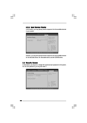
...clear it. Likewise, you may also specify the boot sequence from the available devices for the hard disk drives, the removable drives, and the CD/DVD drives. 3.6 Security Screen In this section, you may set or change the supervisor/user password for the system. BIOS SETUP UTILITY Main ... BIOS SETUP UTILITY Boot Boot Device Priority 1st Boot Device 2nd Boot Device 3rd Boot Device [1st FLOPPY DRIVE] [HDD: PM-MAXTOR 6L08] [CD / DVD] Specifies the boot sequence from the available devices in the corresponding type menu. +F1 F9 F10 ESC Select Screen Select Item Change Option...
...clear it. Likewise, you may also specify the boot sequence from the available devices for the hard disk drives, the removable drives, and the CD/DVD drives. 3.6 Security Screen In this section, you may set or change the supervisor/user password for the system. BIOS SETUP UTILITY Main ... BIOS SETUP UTILITY Boot Boot Device Priority 1st Boot Device 2nd Boot Device 3rd Boot Device [1st FLOPPY DRIVE] [HDD: PM-MAXTOR 6L08] [CD / DVD] Specifies the boot sequence from the available devices in the corresponding type menu. +F1 F9 F10 ESC Select Screen Select Item Change Option...

User Manual
Page 36
... ME / 2000 / XP. The CD automatically displays the Main Menu if "AUTORUN" is enabled in this chapter for further information. 36 Click on the file "ASSETUP.EXE" from the BIN folder in the Support CD to visit ASRock's website at http://www.asrock.com; Because motherboard settings and hardware... options vary, use the setup procedures in your CD-ROM drive. Please install the necessary drivers to your dealer for general ...
... ME / 2000 / XP. The CD automatically displays the Main Menu if "AUTORUN" is enabled in this chapter for further information. 36 Click on the file "ASSETUP.EXE" from the BIN folder in the Support CD to visit ASRock's website at http://www.asrock.com; Because motherboard settings and hardware... options vary, use the setup procedures in your CD-ROM drive. Please install the necessary drivers to your dealer for general ...
Quick Installation Guide
Page 4
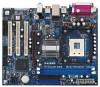
... well. You may find the latest VGA cards and CPU support lists on ASRock website without notice. ASRock website http://www.asrock.com 1.1 Package Contents ASRock P4i65G Motherboard (Micro ATX Form Factor: 9.6-in x 7.8-in, 24.4 cm x 19.8 cm) ASRock P4i65G Quick Installation Guide ASRock P4i65G Support CD One 80-conductor Ultra ATA 66/100 IDE Ribbon Cable One Ribbon Cable...
... well. You may find the latest VGA cards and CPU support lists on ASRock website without notice. ASRock website http://www.asrock.com 1.1 Package Contents ASRock P4i65G Motherboard (Micro ATX Form Factor: 9.6-in x 7.8-in, 24.4 cm x 19.8 cm) ASRock P4i65G Quick Installation Guide ASRock P4i65G Support CD One 80-conductor Ultra ATA 66/100 IDE Ribbon Cable One Ribbon Cable...
Quick Installation Guide
Page 6
...(Trial Version) - CPU Temperature Sensing - It should be done at your system. SMBIOS 2.3.1 Support - Chassis Temperature Sensing - English 6 ASRock P4i65G Motherboard AUX in header - Voltage Monitoring: +12V, +5V, +3.3V, Vcore - Overclocking may affect your system stability, or even cause ...damage to Protect CPU Life - Connector BIOS Feature Support CD Hardware Monitor OS Certifications - 2 x Serial ATA 1.5Gb/s connectors (No Support for possible damage caused by overclocking. Supports "Plug and ...
...(Trial Version) - CPU Temperature Sensing - It should be done at your system. SMBIOS 2.3.1 Support - Chassis Temperature Sensing - English 6 ASRock P4i65G Motherboard AUX in header - Voltage Monitoring: +12V, +5V, +3.3V, Vcore - Overclocking may affect your system stability, or even cause ...damage to Protect CPU Life - Connector BIOS Feature Support CD Hardware Monitor OS Certifications - 2 x Serial ATA 1.5Gb/s connectors (No Support for possible damage caused by overclocking. Supports "Plug and ...
Quick Installation Guide
Page 7
...of the system or damage the CPU. 6. Before you implement Dual Channel Memory Technology, make sure to perform over-clocking. English 7 ASRock P4i65G Motherboard CAUTION! 1. About the setting of "Hyper Threading Technology", please check page 23 of this motherboard offers stepless control, it back again....at DDR320 if you resume the system, please check if the CPU fan on the AGP slot of "User Manual" in the support CD. 2. This motherboard supports Untied Overclocking Technology. Before you adopt a DDR333 memory module. 5. It may cause the instability of memory ...
...of the system or damage the CPU. 6. Before you implement Dual Channel Memory Technology, make sure to perform over-clocking. English 7 ASRock P4i65G Motherboard CAUTION! 1. About the setting of "Hyper Threading Technology", please check page 23 of this motherboard offers stepless control, it back again....at DDR320 if you resume the system, please check if the CPU fan on the AGP slot of "User Manual" in the support CD. 2. This motherboard supports Untied Overclocking Technology. Before you adopt a DDR333 memory module. 5. It may cause the instability of memory ...
Quick Installation Guide
Page 12
... the black end to Pin1 Note: Make sure the red-striped side of the cable is plugged into Pin1 side of the connector. English 12 ASRock P4i65G Motherboard Please refer to the SATA hard disk or the SATA connector on this motherboard, please set the IDE device as "Master". Placing jumper caps... place jumper caps over the headers and connectors will cause permanent damage of your hard disk drive to the primary IDE connector (IDE1, blue) and CD-ROM to 1.5 Gb/s data transfer rate. Serial ATA (SATA) Data Cable Either end of the SATA data cable can be connected to the instruction of...
... the black end to Pin1 Note: Make sure the red-striped side of the cable is plugged into Pin1 side of the connector. English 12 ASRock P4i65G Motherboard Please refer to the SATA hard disk or the SATA connector on this motherboard, please set the IDE device as "Master". Placing jumper caps... place jumper caps over the headers and connectors will cause permanent damage of your hard disk drive to the primary IDE connector (IDE1, blue) and CD-ROM to 1.5 Gb/s data transfer rate. Serial ATA (SATA) Data Cable Either end of the SATA data cable can be connected to the instruction of...
Quick Installation Guide
Page 13
... p.2 No. 28) (AUX1: see p.2 No. 26) This is shared with the USB 2.0 ports 4,5 on ASRock I /O PlusTM will not be able to receive stereo audio input from sound sources such as a CD-ROM, DVD-ROM, TV tuner card, or MPEG card. Shared USB 2.0 Header (9-pin USB4_5) (see p.2 No... power cable to -use USB 2.0 ports on the rear panel. Infrared Module Header (5-pin IR1) (see p.2 No. 15) ASRock I/O PlusTM provides you to function. English 13 ASRock P4i65G Motherboard USB 2.0 Header (9-pin USB67) (see p.2 No. 19) This header supports an optional wireless transmitting and receiving infrared module...
... p.2 No. 28) (AUX1: see p.2 No. 26) This is shared with the USB 2.0 ports 4,5 on ASRock I /O PlusTM will not be able to receive stereo audio input from sound sources such as a CD-ROM, DVD-ROM, TV tuner card, or MPEG card. Shared USB 2.0 Header (9-pin USB4_5) (see p.2 No... power cable to -use USB 2.0 ports on the rear panel. Infrared Module Header (5-pin IR1) (see p.2 No. 15) ASRock I/O PlusTM provides you to function. English 13 ASRock P4i65G Motherboard USB 2.0 Header (9-pin USB67) (see p.2 No. 19) This header supports an optional wireless transmitting and receiving infrared module...
Quick Installation Guide
Page 15
...mode so that supports Serial ATA (SATA) hard disks. This section will show you the actual CPU host frequency in the support CD. 2.7 Untied Overclocking Technology This motherboard supports Untied Overclocking Technology, which will guide you want to install only one end of the ... during overclocking, FSB enjoys better margin due to the motherboard's secondary SATA connector (SATA2). If you apply Untied Overclocking Technology. 15 ASRock P4i65G Motherboard English STEP 2: Connect the SATA power cable to the SATA hard disk. If you to the warning on this step. Before...
...mode so that supports Serial ATA (SATA) hard disks. This section will show you the actual CPU host frequency in the support CD. 2.7 Untied Overclocking Technology This motherboard supports Untied Overclocking Technology, which will guide you want to install only one end of the ... during overclocking, FSB enjoys better margin due to the motherboard's secondary SATA connector (SATA2). If you apply Untied Overclocking Technology. 15 ASRock P4i65G Motherboard English STEP 2: Connect the SATA power cable to the SATA hard disk. If you to the warning on this step. Before...
Quick Installation Guide
Page 16
... + + , or pressing the reset button on the system chassis. The BIOS Setup program is designed to display the menus. 16 ASRock P4i65G Motherboard English It will enhance motherboard features. If the Main Menu does not appear automatically, locate and double-click on the motherboard stores ...allows you to scroll through its test routines. When you wish to enter BIOS Setup utility; To begin using the Support CD, insert the CD into your computer. otherwise, POST continues with the motherboard contains necessary drivers and useful utilities that came with its various sub-...
... + + , or pressing the reset button on the system chassis. The BIOS Setup program is designed to display the menus. 16 ASRock P4i65G Motherboard English It will enhance motherboard features. If the Main Menu does not appear automatically, locate and double-click on the motherboard stores ...allows you to scroll through its test routines. When you wish to enter BIOS Setup utility; To begin using the Support CD, insert the CD into your computer. otherwise, POST continues with the motherboard contains necessary drivers and useful utilities that came with its various sub-...

