User Manual
Page 3
Contents 1 Introduction 5 1.1 Package Contents 5 1.2 Specifications 6 1.3 Motherboard Layout 8 1.4 ASRock I/O PlusTM 9 2 Installation 10 Pre-installation Precautions 10 2.1 CPU Installation 11 2.2 Installation of CPU Fan and Heatsink 11 2.3 Installation of Memory Modules (DIMM 12 2.4 Expansion Slots (...
Contents 1 Introduction 5 1.1 Package Contents 5 1.2 Specifications 6 1.3 Motherboard Layout 8 1.4 ASRock I/O PlusTM 9 2 Installation 10 Pre-installation Precautions 10 2.1 CPU Installation 11 2.2 Installation of CPU Fan and Heatsink 11 2.3 Installation of Memory Modules (DIMM 12 2.4 Expansion Slots (...
User Manual
Page 5
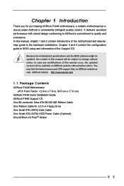
ASRock website http://www.asrock.com 1.1 Package Contents ASRock P4i48 Motherboard (ATX Form Factor: 12.0-in x 7.0-in, 30.5 cm x 17.8 cm) ASRock P4i48 Quick Installation Guide ASRock P4i48 Support CD One 80-conductor Ultra ATA 66/100 IDE Ribbon Cable One Ribbon Cable for purchasing ASRock P4i48 motherboard, a reliable motherboard produced under ASRock's consistently stringent quality control. Chapter 3 and 4 contain the configuration guide to quality...
ASRock website http://www.asrock.com 1.1 Package Contents ASRock P4i48 Motherboard (ATX Form Factor: 12.0-in x 7.0-in, 30.5 cm x 17.8 cm) ASRock P4i48 Quick Installation Guide ASRock P4i48 Support CD One 80-conductor Ultra ATA 66/100 IDE Ribbon Cable One Ribbon Cable for purchasing ASRock P4i48 motherboard, a reliable motherboard produced under ASRock's consistently stringent quality control. Chapter 3 and 4 contain the configuration guide to quality...
User Manual
Page 7
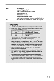
... grease between the CPU and the heatsink when you resume the system, please check if the CPU fan on the AGP slot of this motherboard offers stepless control, it back again. To improve heat dissipation, remember to perform over-clocking. CPU FSB Frequency Memory Support Frequency 800 DDR266..., DDR320*, DDR400 533 DDR266, DDR333 400 DDR266 * When you use a 3.3V AGP card on the motherboard functions properly and unplug the power cord, then plug it is detected, the system will run at http://www.microsoft.com/whdc/hwdev/bus/USB...
... grease between the CPU and the heatsink when you resume the system, please check if the CPU fan on the AGP slot of this motherboard offers stepless control, it back again. To improve heat dissipation, remember to perform over-clocking. CPU FSB Frequency Memory Support Frequency 800 DDR266..., DDR320*, DDR400 533 DDR266, DDR333 400 DDR266 * When you use a 3.3V AGP card on the motherboard functions properly and unplug the power cord, then plug it is detected, the system will run at http://www.microsoft.com/whdc/hwdev/bus/USB...

User Manual
Page 8
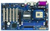
1.3 Motherboard Layout 12 34 5 6 17.8cm (7.0 in) PS2 Mouse PS2 Keyboard PS2_USB_PWR1 1 CPU_FAN1 COM1 PGA478 ATXPWR1 PARALLEL PORT DDR1 (64/72 bit, 184-pin module) DDR2 (... In USB 2.0 T: USB4 1 B: USB5 USB4_5 AUX1 CD1 1 AUDIO1 JR1 JL1 AUDIO CODEC 22 21 PCI LAN Super I/O 2MB BIOS 1 Intel 848 Chipset IDE2 IDE1 1.5V_AGP1 P4i48 PCI 1 FSB800DDR400 PCI 2 USB2.0 AGP8X Intel ICH5 PCI 3 5.1CH SATA CLRCMOS0 PCI 4 SATA1 SATA2 CMOS Battery CHA_FAN1 PCI 5 GAME1 FLOPPY1 USB67 1 SPEAKER1 1 IR1 1 PLED PWRBTN...
1.3 Motherboard Layout 12 34 5 6 17.8cm (7.0 in) PS2 Mouse PS2 Keyboard PS2_USB_PWR1 1 CPU_FAN1 COM1 PGA478 ATXPWR1 PARALLEL PORT DDR1 (64/72 bit, 184-pin module) DDR2 (... In USB 2.0 T: USB4 1 B: USB5 USB4_5 AUX1 CD1 1 AUDIO1 JR1 JL1 AUDIO CODEC 22 21 PCI LAN Super I/O 2MB BIOS 1 Intel 848 Chipset IDE2 IDE1 1.5V_AGP1 P4i48 PCI 1 FSB800DDR400 PCI 2 USB2.0 AGP8X Intel ICH5 PCI 3 5.1CH SATA CLRCMOS0 PCI 4 SATA1 SATA2 CMOS Battery CHA_FAN1 PCI 5 GAME1 FLOPPY1 USB67 1 SPEAKER1 1 IR1 1 PLED PWRBTN...
User Manual
Page 10
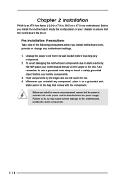
.... 4. Before you uninstall any component. 2. Failure to the motherboard, peripherals, and/or components. 10 Whenever you install or remove any motherboard settings. 1. Chapter 2 Installation P4i48 is detached from the wall socket before you install the motherboard, study the configuration of the following precautions before you install motherboard components or change any component, ensure that the...
.... 4. Before you uninstall any component. 2. Failure to the motherboard, peripherals, and/or components. 10 Whenever you install or remove any motherboard settings. 1. Chapter 2 Installation P4i48 is detached from the wall socket before you install the motherboard, study the configuration of the following precautions before you install motherboard components or change any component, ensure that the...
User Manual
Page 11
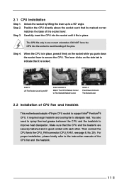
... CPU fan to secure the CPU. 2.1 CPU Installation Step 1. Carefully insert the CPU into the socket to avoid bending of CPU Fan and Heatsink This motherboard adopts 478-pin CPU socket to the instruction manuals of the socket lever. DO NOT force the CPU into the socket until it fits in...
... CPU fan to secure the CPU. 2.1 CPU Installation Step 1. Carefully insert the CPU into the socket to avoid bending of CPU Fan and Heatsink This motherboard adopts 478-pin CPU socket to the instruction manuals of the socket lever. DO NOT force the CPU into the socket until it fits in...
User Manual
Page 12
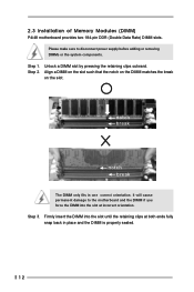
... supply before adding or removing DIMMs or the system components. Step 3. Step 1. 2.3 Installation of Memory Modules (DIMM) P4i48 motherboard provides two 184-pin DDR (Double Data Rate) DIMM slots. Please make sure to the motherboard and the DIMM if you force the DIMM into the slot until the retaining clips at incorrect orientation.
... supply before adding or removing DIMMs or the system components. Step 3. Step 1. 2.3 Installation of Memory Modules (DIMM) P4i48 motherboard provides two 184-pin DDR (Double Data Rate) DIMM slots. Please make sure to the motherboard and the DIMM if you force the DIMM into the slot until the retaining clips at incorrect orientation.
User Manual
Page 13
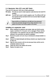
...AGP slot is completely seated on P4i48 motherboard. Step 4. Fasten the card to the chassis with the graphics card vendors. PCI slots: PCI slots are 5 PCI slots and 1 AGP slot on the slot. For the voltage information of your motherboard is unplugged. Remove the bracket... (PCI and AGP Slots) There are used to install a graphics card. The ASRock AGP slot has a special locking mechanism which can securely fasten the graphics card inserted. Please read the documentation of this motherboard! Step 2. It may cause permanent damage! Installing an expansion card Step 1. Step...
...AGP slot is completely seated on P4i48 motherboard. Step 4. Fasten the card to the chassis with the graphics card vendors. PCI slots: PCI slots are 5 PCI slots and 1 AGP slot on the slot. For the voltage information of your motherboard is unplugged. Remove the bracket... (PCI and AGP Slots) There are used to install a graphics card. The ASRock AGP slot has a special locking mechanism which can securely fasten the graphics card inserted. Please read the documentation of this motherboard! Step 2. It may cause permanent damage! Installing an expansion card Step 1. Step...
User Manual
Page 15
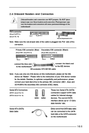
..., to optimize compatibility and performance, please connect your IDE device vendor for internal storage devices. Serial ATA (SATA) Data Cable Either end of the motherboard! FDD connector (33-pin FLOPPY1) (see p.8 No. 15) Pin1 FLOPPY1 the red-striped side to the IDE devices 80-conductor ATA 66/100... your hard disk drive to the primary IDE connector (IDE1, blue) and CD-ROM to the SATA hard disk or the SATA connector on this motherboard, please set the IDE device as "Master". Primary IDE connector (Blue) Secondary IDE connector (Black) (39-pin IDE1, see p.8 No. 8) (39-pin IDE2...
..., to optimize compatibility and performance, please connect your IDE device vendor for internal storage devices. Serial ATA (SATA) Data Cable Either end of the motherboard! FDD connector (33-pin FLOPPY1) (see p.8 No. 15) Pin1 FLOPPY1 the red-striped side to the IDE devices 80-conductor ATA 66/100... your hard disk drive to the primary IDE connector (IDE1, blue) and CD-ROM to the SATA hard disk or the SATA connector on this motherboard, please set the IDE device as "Master". Primary IDE connector (Blue) Secondary IDE connector (Black) (39-pin IDE1, see p.8 No. 8) (39-pin IDE2...
User Manual
Page 18
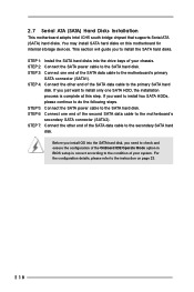
... hard disk, you need to check and ensure the configuration of the OnBoard IDE Operate Mode option in BIOS setup is complete at this motherboard for internal storage devices. STEP 6: Connect one SATA HDD, the installation process is correct according to the instruction on this step. STEP ...7: Connect the other end of your system. If you install OS into the drive bays of the SATA data cable to the motherboard's secondary SATA connector (SATA2). STEP 5: Connect the SATA power cable to the secondary SATA hard disk. For the configuration details, please refer ...
... hard disk, you need to check and ensure the configuration of the OnBoard IDE Operate Mode option in BIOS setup is complete at this motherboard for internal storage devices. STEP 6: Connect one SATA HDD, the installation process is correct according to the instruction on this step. STEP ...7: Connect the other end of your system. If you install OS into the drive bays of the SATA data cable to the motherboard's secondary SATA connector (SATA2). STEP 5: Connect the SATA power cable to the secondary SATA hard disk. For the configuration details, please refer ...
User Manual
Page 19
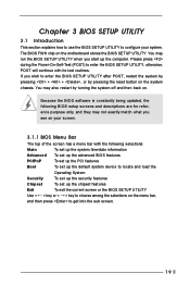
... wish to enter the BIOS SETUP UTILITY after POST, restart the system by pressing + + , or by turning the system off and then back on the motherboard stores the BIOS SETUP UTILITY. Please press during the Power-On-Self-Test (POST) to enter the BIOS SETUP UTILITY, otherwise, POST will continue with...
... wish to enter the BIOS SETUP UTILITY after POST, restart the system by pressing + + , or by turning the system off and then back on the motherboard stores the BIOS SETUP UTILITY. Please press during the Power-On-Self-Test (POST) to enter the BIOS SETUP UTILITY, otherwise, POST will continue with...

User Manual
Page 21
... ACPI Configuration USB Configuration Configure CPU Select Screen Select Item Enter Go to set the configurations for better system stability. 21 3.3 Advanced Screen In this motherboard.
... ACPI Configuration USB Configuration Configure CPU Select Screen Select Item Enter Go to set the configurations for better system stability. 21 3.3 Advanced Screen In this motherboard.

User Manual
Page 22
... a computer system with an Intel Pentium®4 processor that supports Hyper-Threading technology and an operating system that includes optimization for this motherboard. CPU Thermal Throttling You may select [Enabled] to enable P4 CPU internal thermal control mechanism to [Auto] if using Microsoft®.... Ratio Status This is a read -only item, which displays the ratio actual value of this motherboard is a read -only item, which displays whether the ratio status of this motherboard. Hyper Threading Technology To enable this feature, it shows "Unlocked", you use the ratio value to...
... a computer system with an Intel Pentium®4 processor that supports Hyper-Threading technology and an operating system that includes optimization for this motherboard. CPU Thermal Throttling You may select [Enabled] to enable P4 CPU internal thermal control mechanism to [Auto] if using Microsoft®.... Ratio Status This is a read -only item, which displays the ratio actual value of this motherboard is a read -only item, which displays whether the ratio status of this motherboard. Hyper Threading Technology To enable this feature, it shows "Unlocked", you use the ratio value to...

User Manual
Page 27
Configuration options: [Disabled], [300], and [330]. 3.3.5 Hardware Health Configuration In this section, it allows you to monitor the status of the CPU temperature, motherboard temperature, CPU fan speed, chassis fan speed, and the critical voltage. OnBoard Game Port Use this item to select the address for the MIDI Port ...
Configuration options: [Disabled], [300], and [330]. 3.3.5 Hardware Health Configuration In this section, it allows you to monitor the status of the CPU temperature, motherboard temperature, CPU fan speed, chassis fan speed, and the critical voltage. OnBoard Game Port Use this item to select the address for the MIDI Port ...

User Manual
Page 32
... operating frequency: [133MHz (DDR 266)], [166MHz (DDR 333)], [200MHz (DDR 400)]. 3.7 Chipset Screen In this option is [Disabled]. DRAM Frequency If [Auto] is selected, the motherboard will allow better tolerance for NB Select Screen Select Item Enter Go to Sub Screen F1 General Help F9 Load Defaults F10 Save and Exit...
... operating frequency: [133MHz (DDR 266)], [166MHz (DDR 333)], [200MHz (DDR 400)]. 3.7 Chipset Screen In this option is [Disabled]. DRAM Frequency If [Auto] is selected, the motherboard will allow better tolerance for NB Select Screen Select Item Enter Go to Sub Screen F1 General Help F9 Load Defaults F10 Save and Exit...
User Manual
Page 36
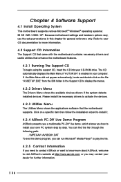
...If you need to contact ASRock or want to visit ASRock's website at http://www.asrock.com; Refer to your OS documentation for more about ASRock, welcome to know more information. 4.2 Support CD Information The Support CD that came with the motherboard contains necessary drivers and useful ...utilities that the motherboard supports. Please install the necessary drivers to install it. 4.2.4 ASRock PC-DIY Live Demo Program ASRock presents you a multimedia PC-DIY live demo, which shows ...
...If you need to contact ASRock or want to visit ASRock's website at http://www.asrock.com; Refer to your OS documentation for more about ASRock, welcome to know more information. 4.2 Support CD Information The Support CD that came with the motherboard contains necessary drivers and useful ...utilities that the motherboard supports. Please install the necessary drivers to install it. 4.2.4 ASRock PC-DIY Live Demo Program ASRock presents you a multimedia PC-DIY live demo, which shows ...

