User Manual
Page 3
Contents 1 Introduction 5 1.1 Package Contents 5 1.2 Specifications 6 1.3 Motherboard Layout 8 1.4 ASRock I/O PlusTM 9 2 Installation 10 Pre-installation Precautions 10 2.1 CPU Installation 11 2.2 Installation of CPU Fan and Heatsink 11 2.3 Installation... 14 2.6 Onboard Headers and Connectors 15 2.7 Serial ATA (SATA) Hard Disks Installation 18 2.8 Making An SATA Driver Diskette 18 3 BIOS SETUP UTILITY 19 3.1 Introduction 19 3.1.1 BIOS Menu Bar 19 3.1.2 Navigation Keys 20 3.2 Main Screen 20 3.3 Advanced Screen 21 3.3.1 CPU Configuration 21 3.3.2 IDE Configuration 23 3.3.3 ...
Contents 1 Introduction 5 1.1 Package Contents 5 1.2 Specifications 6 1.3 Motherboard Layout 8 1.4 ASRock I/O PlusTM 9 2 Installation 10 Pre-installation Precautions 10 2.1 CPU Installation 11 2.2 Installation of CPU Fan and Heatsink 11 2.3 Installation... 14 2.6 Onboard Headers and Connectors 15 2.7 Serial ATA (SATA) Hard Disks Installation 18 2.8 Making An SATA Driver Diskette 18 3 BIOS SETUP UTILITY 19 3.1 Introduction 19 3.1.1 BIOS Menu Bar 19 3.1.2 Navigation Keys 20 3.2 Main Screen 20 3.3 Advanced Screen 21 3.3.1 CPU Configuration 21 3.3.2 IDE Configuration 23 3.3.3 ...
User Manual
Page 5
... the updated version will be available on ASRock website as well. ASRock website http://www.asrock.com 1.1 Package Contents ASRock P4i48 Motherboard (ATX Form Factor: 12.0-in x 7.0-in, 30.5 cm x 17.8 cm) ASRock P4i48 Quick Installation Guide ASRock P4i48 Support CD One 80-conductor Ultra ATA ...66/100 IDE Ribbon Cable One Ribbon Cable for purchasing ASRock P4i48 motherboard, a reliable motherboard produced under ASRock's consistently stringent quality control. Because the motherboard specifications and the BIOS software might be updated, the content of the Support CD. Chapter ...
... the updated version will be available on ASRock website as well. ASRock website http://www.asrock.com 1.1 Package Contents ASRock P4i48 Motherboard (ATX Form Factor: 12.0-in x 7.0-in, 30.5 cm x 17.8 cm) ASRock P4i48 Quick Installation Guide ASRock P4i48 Support CD One 80-conductor Ultra ATA ...66/100 IDE Ribbon Cable One Ribbon Cable for purchasing ASRock P4i48 motherboard, a reliable motherboard produced under ASRock's consistently stringent quality control. Because the motherboard specifications and the BIOS software might be updated, the content of the Support CD. Chapter ...
User Manual
Page 7
.... Although this motherboard offers stepless control, it is detected, the system will run at http://www.microsoft.com/whdc/hwdev/bus/USB/USB2support.mspx 6. BIOS: OS: AMI legal BIOS, Supports "Plug and Play", ACPI 1.1 compliance wake up events, Supports jumperfree, SMBIOS 2.3.1 support, CPU frequency stepless control (only for the memory support frequency...
.... Although this motherboard offers stepless control, it is detected, the system will run at http://www.microsoft.com/whdc/hwdev/bus/USB/USB2support.mspx 6. BIOS: OS: AMI legal BIOS, Supports "Plug and Play", ACPI 1.1 compliance wake up events, Supports jumperfree, SMBIOS 2.3.1 support, CPU frequency stepless control (only for the memory support frequency...

User Manual
Page 8
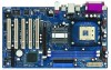
...Bottom: Mic In USB 2.0 T: USB4 1 B: USB5 USB4_5 AUX1 CD1 1 AUDIO1 JR1 JL1 AUDIO CODEC 22 21 PCI LAN Super I/O 2MB BIOS 1 Intel 848 Chipset IDE2 IDE1 1.5V_AGP1 P4i48 PCI 1 FSB800DDR400 PCI 2 USB2.0 AGP8X Intel ICH5 PCI 3 5.1CH SATA CLRCMOS0 PCI 4 SATA1 SATA2 CMOS Battery CHA_FAN1 PCI 5 GAME1 FLOPPY1 ... 1) 17 System Panel Header (PANEL1) 18 Infrared Module Header (IR1) 19 USB 2.0 Header (USB67, Blue) 20 Game Port Connector (GAME1) 21 BIOS FWH Chip 22 PCI Slots (PCI1- 5) 23 JL1 Jumper 24 JR1 Jumper 25 Front Panel Audio Header (AUDIO1) 26 Internal Audio Connector: AUX1 (White...
...Bottom: Mic In USB 2.0 T: USB4 1 B: USB5 USB4_5 AUX1 CD1 1 AUDIO1 JR1 JL1 AUDIO CODEC 22 21 PCI LAN Super I/O 2MB BIOS 1 Intel 848 Chipset IDE2 IDE1 1.5V_AGP1 P4i48 PCI 1 FSB800DDR400 PCI 2 USB2.0 AGP8X Intel ICH5 PCI 3 5.1CH SATA CLRCMOS0 PCI 4 SATA1 SATA2 CMOS Battery CHA_FAN1 PCI 5 GAME1 FLOPPY1 ... 1) 17 System Panel Header (PANEL1) 18 Infrared Module Header (IR1) 19 USB 2.0 Header (USB67, Blue) 20 Game Port Connector (GAME1) 21 BIOS FWH Chip 22 PCI Slots (PCI1- 5) 23 JL1 Jumper 24 JR1 Jumper 25 Front Panel Audio Header (AUDIO1) 26 Internal Audio Connector: AUX1 (White...

User Manual
Page 14
... setup, please turn off the computer and unplug the power cord, then use a jumper cap to clear the CMOS when you just finish updating the BIOS, you must boot up events. JR1(see p.8 No. 24) JL1(see p.8 No. 14) 2-pin jumper Note: CLRCMOS0 allows you do the clear-CMOS action. 14...
... setup, please turn off the computer and unplug the power cord, then use a jumper cap to clear the CMOS when you just finish updating the BIOS, you must boot up events. JR1(see p.8 No. 24) JL1(see p.8 No. 14) 2-pin jumper Note: CLRCMOS0 allows you do the clear-CMOS action. 14...
User Manual
Page 18
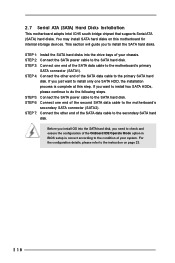
... the SATA hard disks into the SATA hard disk, you need to check and ensure the configuration of the OnBoard IDE Operate Mode option in BIOS setup is complete at this motherboard for internal storage devices. STEP 3: Connect one end of the second SATA data cable to the SATA hard disk...
... the SATA hard disks into the SATA hard disk, you need to check and ensure the configuration of the OnBoard IDE Operate Mode option in BIOS setup is complete at this motherboard for internal storage devices. STEP 3: Connect one end of the second SATA data cable to the SATA hard disk...
User Manual
Page 19
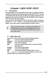
... you see on your system. You may also restart by pressing the reset button on the menu bar, and then press to configure your screen. 3.1.1 BIOS Menu Bar The top of the screen has a menu bar with its test routines. Please press during the Power-On-Self-Test (POST) to enter... UTILITY, otherwise, POST will continue with the following selections: Main To set up the system time/date information Advanced To set up the advanced BIOS features PCIPnP To set up the PCI features Boot To set up the default system device to locate and load the Operating System Security To ...
... you see on your system. You may also restart by pressing the reset button on the menu bar, and then press to configure your screen. 3.1.1 BIOS Menu Bar The top of the screen has a menu bar with its test routines. Please press during the Power-On-Self-Test (POST) to enter... UTILITY, otherwise, POST will continue with the following selections: Main To set up the system time/date information Advanced To set up the advanced BIOS features PCIPnP To set up the PCI features Boot To set up the default system device to locate and load the Operating System Security To ...
User Manual
Page 20
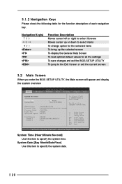
...To jump to the Exit Screen or exit the current screen 3.2 Main Screen When you enter the BIOS SETUP UTILITY, the Main screen will appear and display the system overview BIOS SETUP UTILITY Main Advanced PCI PnP Boot Security Chipset Exit System Overview System Time System Date [14:...00:09] [Tue 01/13/2004] BIOS Version : P4i48 BIOS P1.00 Processor Type : Intel (R) Pentium (R) 4 CPU 2.40 GHz Processor Speed : 2400 MHz Cache Size : 512KB Microcode Update : 0F29/17 Total Memory DIMM 1 ...
...To jump to the Exit Screen or exit the current screen 3.2 Main Screen When you enter the BIOS SETUP UTILITY, the Main screen will appear and display the system overview BIOS SETUP UTILITY Main Advanced PCI PnP Boot Security Chipset Exit System Overview System Time System Date [14:...00:09] [Tue 01/13/2004] BIOS Version : P4i48 BIOS P1.00 Processor Type : Intel (R) Pentium (R) 4 CPU 2.40 GHz Processor Speed : 2400 MHz Cache Size : 512KB Microcode Update : 0F29/17 Total Memory DIMM 1 ...

User Manual
Page 21
..., SuperIO Configuration, Hardware Health Configuration, ACPI Configuration, and USB Configuration. 3.3 Advanced Screen In this motherboard. Main BIOS SETUP UTILITY Advanced PCI PnP Boot Security Chipset Exit Advanced Settings WARNING : Setting wrong values in this section may cause...] for the following item. Setting wrong values in below sections may cause the system to malfunction. 3.3.1 CPU Configuration Advanced BIOS SETUP UTILITY CPU Configuration CPU Host Frequency Actual Frequency (MHz) Spread Spectrum Ratio Status Ratio Actual Value CPU Thermal Throttling [...
..., SuperIO Configuration, Hardware Health Configuration, ACPI Configuration, and USB Configuration. 3.3 Advanced Screen In this motherboard. Main BIOS SETUP UTILITY Advanced PCI PnP Boot Security Chipset Exit Advanced Settings WARNING : Setting wrong values in this section may cause...] for the following item. Setting wrong values in below sections may cause the system to malfunction. 3.3.1 CPU Configuration Advanced BIOS SETUP UTILITY CPU Configuration CPU Host Frequency Actual Frequency (MHz) Spread Spectrum Ratio Status Ratio Actual Value CPU Thermal Throttling [...
User Manual
Page 23
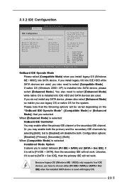
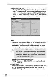
... SATA device, please select [Enhanced Mode]. Likewise, if it is set to [Pri IDE + SATA], then the secondary IDE will not work . 3.3.2 IDE Configuration Advanced BIOS SETUP UTILITY IDE Configuration OnBoard IDE Operate Mode OnBoard IDE Controller Primary IDE Master Primary IDE Slave Secondary IDE Master Secondary IDE Slave SATA1 SATA2...
... SATA device, please select [Enhanced Mode]. Likewise, if it is set to [Pri IDE + SATA], then the secondary IDE will not work . 3.3.2 IDE Configuration Advanced BIOS SETUP UTILITY IDE Configuration OnBoard IDE Operate Mode OnBoard IDE Controller Primary IDE Master Primary IDE Slave Secondary IDE Master Secondary IDE Slave SATA1 SATA2...
User Manual
Page 24
... necessary so that you can be applied to configure the type of the IDE device that you specify. After selecting the hard disk information into BIOS, use a disk utility, such as the example in the following instruction, which can write or read data from the hard disk. Make sure to set... format the new IDE hard disk drives. We will use of "Primary IDE Slave", "Secondary IDE Master", "Secondary IDE Slave", "SATA1" and "SATA2" as well. BIOS SETUP UTILITY Advanced Primary IDE Master Device Vendor Size LBA Mode Block Mode PIO Mode Async DMA Ultra DMA S.M.A.R.T.
... necessary so that you can be applied to configure the type of the IDE device that you specify. After selecting the hard disk information into BIOS, use a disk utility, such as the example in the following instruction, which can write or read data from the hard disk. Make sure to set... format the new IDE hard disk drives. We will use of "Primary IDE Slave", "Secondary IDE Master", "Secondary IDE Slave", "SATA1" and "SATA2" as well. BIOS SETUP UTILITY Advanced Primary IDE Master Device Vendor Size LBA Mode Block Mode PIO Mode Async DMA Ultra DMA S.M.A.R.T.
User Manual
Page 25
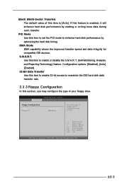
... F10 ESC Select Screen Select Item Change Option General Help Load Defaults Save and Exit Exit v02.54 (C) Copyright 1985-2003, American Megatrends, Inc. 25 BIOS SETUP UTILITY Advanced Floppy Configuration Floppy A Floppy B [1.44 MB 312"] [Disabled] Select the type of this item is enabled, it will enhance hard disk performance...
... F10 ESC Select Screen Select Item Change Option General Help Load Defaults Save and Exit Exit v02.54 (C) Copyright 1985-2003, American Megatrends, Inc. 25 BIOS SETUP UTILITY Advanced Floppy Configuration Floppy A Floppy B [1.44 MB 312"] [Disabled] Select the type of this item is enabled, it will enhance hard disk performance...
User Manual
Page 26
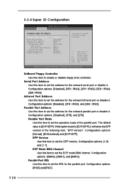
...[ECP+EPP]. If this item to set to set the operation mode of the parallel port. 3.3.4 Super IO Configuration Advanced BIOS SETUP UTILITY Configure Super IO Chipset OnBoard Floppy Controller Serial Port Address Infrared Port Address Parallel Port Address Parallel Port Mode EPP ... Game Port OnBoard MIDI Port [Enabled] [3F8 / IRQ4] [Disabled] [378] [ECP + EPP] [1.9] [DMA3] [IRQ7] [Enabled] [Disabled] Allow BIOS to enable or disable floppy drive controller. Parallel Port Address Use this item to set the ECP mode DMA channel. Configuration options: [Normal], [Bi-Directional...
...[ECP+EPP]. If this item to set to set the operation mode of the parallel port. 3.3.4 Super IO Configuration Advanced BIOS SETUP UTILITY Configure Super IO Chipset OnBoard Floppy Controller Serial Port Address Infrared Port Address Parallel Port Address Parallel Port Mode EPP ... Game Port OnBoard MIDI Port [Enabled] [3F8 / IRQ4] [Disabled] [378] [ECP + EPP] [1.9] [DMA3] [IRQ7] [Enabled] [Disabled] Allow BIOS to enable or disable floppy drive controller. Parallel Port Address Use this item to set the ECP mode DMA channel. Configuration options: [Normal], [Bi-Directional...

User Manual
Page 27
Advanced BIOS SETUP UTILITY Hardware Health Event Monitoring CPU Temperature M / B Temperature CPU Fan Speed Chassis Fan Speed Vcore + 3.30V + 5.00V + 12.00V : 37 C / 98 F : 31 C / 87 F : 2463 ... F10 ESC Select Screen Select Item General Help Load Defaults Save and Exit Exit v02.54 (C) Copyright 1985-2003, American Megatrends, Inc. 3.3.6 ACPI Configuration Advanced BIOS SETUP UTILITY ACPI Settings Suspend To RAM Restore on your system, including the parameters of the hardware on AC / Power Loss Ring-In Power On...
Advanced BIOS SETUP UTILITY Hardware Health Event Monitoring CPU Temperature M / B Temperature CPU Fan Speed Chassis Fan Speed Vcore + 3.30V + 5.00V + 12.00V : 37 C / 98 F : 31 C / 87 F : 2463 ... F10 ESC Select Screen Select Item General Help Load Defaults Save and Exit Exit v02.54 (C) Copyright 1985-2003, American Megatrends, Inc. 3.3.6 ACPI Configuration Advanced BIOS SETUP UTILITY ACPI Settings Suspend To RAM Restore on your system, including the parameters of the hardware on AC / Power Loss Ring-In Power On...
User Manual
Page 28
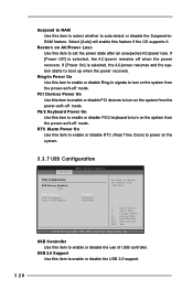
...-In signals to boot up when the power recovers. Suspend to RAM Use this item to select whether to power on the system. 3.3.7 USB Configuration BIOS SETUP UTILITY Advanced USB Configuration USB Devices Enabled : None USB Controller USB 2.0 Support Legacy USB Support [Enabled] [Enabled] [Disabled] To enable or disable the onboard...
...-In signals to boot up when the power recovers. Suspend to RAM Use this item to select whether to power on the system. 3.3.7 USB Configuration BIOS SETUP UTILITY Advanced USB Configuration USB Devices Enabled : None USB Controller USB 2.0 Support Legacy USB Support [Enabled] [Enabled] [Disabled] To enable or disable the onboard...
User Manual
Page 29
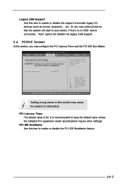
... and the PCI IDE Bus Master. if there is 64. It is recommended to enable or disable the PCI IDE BusMaster feature. 29 Main Advanced BIOS SETUP UTILITY PCIPnP Boot Security Chipset Exit Advanced PCI / PnP Settings WARNING : Setting wrong values in units of PCI clocks for PCI device latency timer...
... and the PCI IDE Bus Master. if there is 64. It is recommended to enable or disable the PCI IDE BusMaster feature. 29 Main Advanced BIOS SETUP UTILITY PCIPnP Boot Security Chipset Exit Advanced PCI / PnP Settings WARNING : Setting wrong values in units of PCI clocks for PCI device latency timer...

User Manual
Page 30
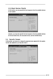
... this section, it will display the available devices on your system for you to configure the boot settings and the boot priority. BIOS SETUP UTILITY Main Advanced PCIPnP Boot Security Chipset Exit Boot Settings Boot Settings Configuration Boot Device Priority Hard Disk Drives Removable Drives CD...Help F9 Load Defaults F10 Save and Exit ESC Exit v02.54 (C) Copyright 1985-2003, American Megatrends, Inc. 3.5.1 Boot Settings Configuration BIOS SETUP UTILITY Boot Boot Settings Configuration Boot From Network Bootup Num-Lock [Disabled] [On] To enable or disable the boot from network feature...
... this section, it will display the available devices on your system for you to configure the boot settings and the boot priority. BIOS SETUP UTILITY Main Advanced PCIPnP Boot Security Chipset Exit Boot Settings Boot Settings Configuration Boot Device Priority Hard Disk Drives Removable Drives CD...Help F9 Load Defaults F10 Save and Exit ESC Exit v02.54 (C) Copyright 1985-2003, American Megatrends, Inc. 3.5.1 Boot Settings Configuration BIOS SETUP UTILITY Boot Boot Settings Configuration Boot From Network Bootup Num-Lock [Disabled] [On] To enable or disable the boot from network feature...
User Manual
Page 31
...Enter Change F1 General Help F9 Load Defaults F10 Save and Exit ESC Exit v02.54 (C) Copyright 1985-2003, American Megatrends, Inc. 31 BIOS SETUP UTILITY Boot Boot Device Priority 1st Boot Device 2nd Boot Device 3rd Boot Device [1st FLOPPY DRIVE] [HDD: PM-MAXTOR 6L08] ... Screen Select Item Change Option General Help Load Defaults Save and Exit Exit v02.54 (C) Copyright 1985-2003, American Megatrends, Inc. BIOS SETUP UTILITY Main Advanced PCIPnP Boot Security Chipset Exit Security Settings Supervisor Password : Not Installed User Password : Not Installed Change Supervisor Password...
...Enter Change F1 General Help F9 Load Defaults F10 Save and Exit ESC Exit v02.54 (C) Copyright 1985-2003, American Megatrends, Inc. 31 BIOS SETUP UTILITY Boot Boot Device Priority 1st Boot Device 2nd Boot Device 3rd Boot Device [1st FLOPPY DRIVE] [HDD: PM-MAXTOR 6L08] ... Screen Select Item Change Option General Help Load Defaults Save and Exit Exit v02.54 (C) Copyright 1985-2003, American Megatrends, Inc. BIOS SETUP UTILITY Main Advanced PCIPnP Boot Security Chipset Exit Security Settings Supervisor Password : Not Installed User Password : Not Installed Change Supervisor Password...

User Manual
Page 32
...Change Option General Help Load Defaults Save and Exit Exit v02.54 (C) Copyright 1985-2003, American Megatrends, Inc. BIOS SETUP UTILITY Main Advanced PCIPnP Boot Security Chipset Exit Chipset Settings NorthBridge Configuration SouthBridge Configuration Options for NB Select Screen Select...Load Defaults F10 Save and Exit ESC Exit v02.54 (C) Copyright 1985-2003, American Megatrends, Inc. 3.7.1 NorthBridge Chipset Configuration BIOS SETUP UTILITY NorthBridge Chipset Configuration DRAM Frequency Flexibility Option Configure DRAM Timing by SPD DRAM CAS# Latency DRAM RAS# Precharge DRAM ...
...Change Option General Help Load Defaults Save and Exit Exit v02.54 (C) Copyright 1985-2003, American Megatrends, Inc. BIOS SETUP UTILITY Main Advanced PCIPnP Boot Security Chipset Exit Chipset Settings NorthBridge Configuration SouthBridge Configuration Options for NB Select Screen Select...Load Defaults F10 Save and Exit ESC Exit v02.54 (C) Copyright 1985-2003, American Megatrends, Inc. 3.7.1 NorthBridge Chipset Configuration BIOS SETUP UTILITY NorthBridge Chipset Configuration DRAM Frequency Flexibility Option Configure DRAM Timing by SPD DRAM CAS# Latency DRAM RAS# Precharge DRAM ...
User Manual
Page 34
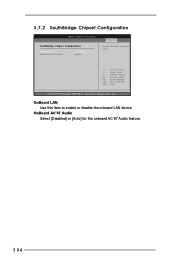
OnBoard AC'97 Audio Select [Disabled] or [Auto] for the onboard AC'97 Audio feature. 34 3.7.2 SouthBridge Chipset Configuration BIOS SETUP UTILITY SouthBridge Chipset Configuration Onboard LAN Onboard AC97 Audio [Enabled] [Auto] Chipset Enable / Disable onboard LAN. +F1 F9 F10 ESC Select Screen Select Item Change Option General Help Load Defaults Save and Exit Exit v02.54 (C) Copyright 1985-2003, American Megatrends, Inc. OnBoard LAN Use this item to enable or disable the onboard LAN device.
OnBoard AC'97 Audio Select [Disabled] or [Auto] for the onboard AC'97 Audio feature. 34 3.7.2 SouthBridge Chipset Configuration BIOS SETUP UTILITY SouthBridge Chipset Configuration Onboard LAN Onboard AC97 Audio [Enabled] [Auto] Chipset Enable / Disable onboard LAN. +F1 F9 F10 ESC Select Screen Select Item Change Option General Help Load Defaults Save and Exit Exit v02.54 (C) Copyright 1985-2003, American Megatrends, Inc. OnBoard LAN Use this item to enable or disable the onboard LAN device.


