User Manual
Page 3
... 4 1.1 Package Contents 4 1.2 Specifications 5 1.3 Motherboard Layout (P4i45G 8 1.4 Motherboard Layout (P4i45GL 9 1.5 Motherboard Layout (P4i45GV 10 1.6 ASRock I/OTM (P4i45G / P4i45GL / P4i45GV 11 2 Installation 12 2.1 Screw Holes 12... 2.2 Pre-installation Precautions 12 2.3 CPU Installation 12 2.4 Installation of Heatsink and CPU fan 13 2.5 Installation of Memory Modules (DIMM 13 2.6 Expansion Slots 14 2.7 Jumpers Setup 15 2.8 Connectors 16 3 BIOS Setup 18 3.1 BIOS Setup Utility 18 3.1.1 BIOS...
... 4 1.1 Package Contents 4 1.2 Specifications 5 1.3 Motherboard Layout (P4i45G 8 1.4 Motherboard Layout (P4i45GL 9 1.5 Motherboard Layout (P4i45GV 10 1.6 ASRock I/OTM (P4i45G / P4i45GL / P4i45GV 11 2 Installation 12 2.1 Screw Holes 12... 2.2 Pre-installation Precautions 12 2.3 CPU Installation 12 2.4 Installation of Heatsink and CPU fan 13 2.5 Installation of Memory Modules (DIMM 13 2.6 Expansion Slots 14 2.7 Jumpers Setup 15 2.8 Connectors 16 3 BIOS Setup 18 3.1 BIOS Setup Utility 18 3.1.1 BIOS...
User Manual
Page 4
... endurance. Chapter 1 Introduction Thank you for floppy drive (1 x ribbon cable) 1 ASRock I/O shield 1 COM port bracket 4 Chapter 3 and 4 contain basic BIOS setup and Support CD information. For advanced users' reference, the Appendix appearing on ASRock website without notice. ASRock website http://www.asrock.com 1.1 Package Contents ASRock P4i45G or P4i45GL or P4i45GV motherboard (Micro ATX form factor: 9.6" x 9.6", 24...
... endurance. Chapter 1 Introduction Thank you for floppy drive (1 x ribbon cable) 1 ASRock I/O shield 1 COM port bracket 4 Chapter 3 and 4 contain basic BIOS setup and Support CD information. For advanced users' reference, the Appendix appearing on ASRock website without notice. ASRock website http://www.asrock.com 1.1 Package Contents ASRock P4i45G or P4i45GL or P4i45GV motherboard (Micro ATX form factor: 9.6" x 9.6", 24...
User Manual
Page 6
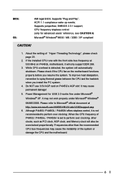
...To improve heat dissipation, remember to perform over clocking, other than the recommended CPU bus frequencies may cause permanent damage! 5. BIOS: OS: AMI legal BIOS; SMBIOS 2.3.1 support; If the installed CPU runs with the front side bus frequency at http://www.microsoft.com/HWDEV/BUS/...98/ME/2000. Do NOT use 3.3V AGP card on P4i45GL motherboard, it is detected, the system will only support DDR 266. 3. Although P4i45G / P4i45GL / P4i45GV offers stepless control, it will automatically shutdown. About the setting of the system or damage the CPU and the motherboard. 6 ...
...To improve heat dissipation, remember to perform over clocking, other than the recommended CPU bus frequencies may cause permanent damage! 5. BIOS: OS: AMI legal BIOS; SMBIOS 2.3.1 support; If the installed CPU runs with the front side bus frequency at http://www.microsoft.com/HWDEV/BUS/...98/ME/2000. Do NOT use 3.3V AGP card on P4i45GL motherboard, it is detected, the system will only support DDR 266. 3. Although P4i45G / P4i45GL / P4i45GV offers stepless control, it will automatically shutdown. About the setting of the system or damage the CPU and the motherboard. 6 ...
User Manual
Page 8
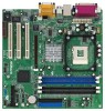
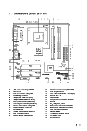
...CD1 Intel 845G Chipset 23 21 20 19 18 MMInicicin AUX1 1 AUDIO1 PCI LAN Audio CODEC Super I/O AGP 1 PCI 1 PCI 2 P4i45G PCI 3 11 2MB BIOS 5.1CH AMR1 USB2.0 26 01 23 01 23 IDE2 IDE1 CMOS Battery Intel ICH4 CLRCMOS0 CHA_FAN1 ` COM1 1 FLOPPY1 USB45 1 SPEAKER1 1...) 7 Primary IDE connector (IDE1, Blue) 8 Secondary IDE connector (IDE2, Black) 9 Chassis fan connector (CHA_FAN1) 10 Floppy connector (FLOPPY1) 11 BIOS FWH chip 12 System panel connector (PANEL1) 13 USB 2.0 header (USB45) 14 Infrared module connector (IR1) 15 External speaker connector (SPEAKER1) 16 South...
...CD1 Intel 845G Chipset 23 21 20 19 18 MMInicicin AUX1 1 AUDIO1 PCI LAN Audio CODEC Super I/O AGP 1 PCI 1 PCI 2 P4i45G PCI 3 11 2MB BIOS 5.1CH AMR1 USB2.0 26 01 23 01 23 IDE2 IDE1 CMOS Battery Intel ICH4 CLRCMOS0 CHA_FAN1 ` COM1 1 FLOPPY1 USB45 1 SPEAKER1 1...) 7 Primary IDE connector (IDE1, Blue) 8 Secondary IDE connector (IDE2, Black) 9 Chassis fan connector (CHA_FAN1) 10 Floppy connector (FLOPPY1) 11 BIOS FWH chip 12 System panel connector (PANEL1) 13 USB 2.0 header (USB45) 14 Infrared module connector (IR1) 15 External speaker connector (SPEAKER1) 16 South...

User Manual
Page 9
...Intel 845GL Chipset 23 21 20 19 18 MMInicicin AUX1 1 AUDIO1 PCI LAN Audio CODEC Super I/O PCI 1 PCI 2 P4i45GL PCI 3 11 2MB BIOS 5.1CH AMR1 USB2.0 26 01 23 01 23 IDE2 IDE1 CMOS Battery Intel ICH4 CLRCMOS0 CHA_FAN1 ` COM1 1 FLOPPY1 USB45 1 SPEAKER1 1 IR1 ...) 7 Primary IDE connector (IDE1, Blue) 8 Secondary IDE connector (IDE2, Black) 9 Chassis fan connector (CHA_FAN1) 10 Floppy connector (FLOPPY1) 11 BIOS FWH chip 12 System panel connector (PANEL1) 13 USB 2.0 header (USB45) 14 Infrared module connector (IR1) 15 External speaker connector (SPEAKER1) 16 South...
...Intel 845GL Chipset 23 21 20 19 18 MMInicicin AUX1 1 AUDIO1 PCI LAN Audio CODEC Super I/O PCI 1 PCI 2 P4i45GL PCI 3 11 2MB BIOS 5.1CH AMR1 USB2.0 26 01 23 01 23 IDE2 IDE1 CMOS Battery Intel ICH4 CLRCMOS0 CHA_FAN1 ` COM1 1 FLOPPY1 USB45 1 SPEAKER1 1 IR1 ...) 7 Primary IDE connector (IDE1, Blue) 8 Secondary IDE connector (IDE2, Black) 9 Chassis fan connector (CHA_FAN1) 10 Floppy connector (FLOPPY1) 11 BIOS FWH chip 12 System panel connector (PANEL1) 13 USB 2.0 header (USB45) 14 Infrared module connector (IR1) 15 External speaker connector (SPEAKER1) 16 South...

User Manual
Page 10
...Intel 845GV Chipset 23 21 20 19 18 MMInicicin AUX1 1 AUDIO1 PCI LAN Audio CODEC Super I/O PCI 1 PCI 2 P4i45GV PCI 3 11 2MB BIOS 5.1CH AMR1 USB2.0 26 01 23 01 23 IDE2 IDE1 Intel ICH4 CMOS Battery CLRCMOS0 CHA_FAN1 ` COM1 1 FLOPPY1 USB45 1 SPEAKER1 1 IR1 ...Black) 7 Primary IDE connector (IDE1, Blue) 8 Secondary IDE connector (IDE2, Black) 9 Chassis fan connector (CHA_FAN1) 10 Floppy connector (FLOPPY1) 11 BIOS FWH chip 12 System panel connector (PANEL1) 13 USB 2.0 header (USB45) 14 Infrared module connector (IR1) 15 External speaker connector (SPEAKER1) 16 South...
...Intel 845GV Chipset 23 21 20 19 18 MMInicicin AUX1 1 AUDIO1 PCI LAN Audio CODEC Super I/O PCI 1 PCI 2 P4i45GV PCI 3 11 2MB BIOS 5.1CH AMR1 USB2.0 26 01 23 01 23 IDE2 IDE1 Intel ICH4 CMOS Battery CLRCMOS0 CHA_FAN1 ` COM1 1 FLOPPY1 USB45 1 SPEAKER1 1 IR1 ...Black) 7 Primary IDE connector (IDE1, Blue) 8 Secondary IDE connector (IDE2, Black) 9 Chassis fan connector (CHA_FAN1) 10 Floppy connector (FLOPPY1) 11 BIOS FWH chip 12 System panel connector (PANEL1) 13 USB 2.0 header (USB45) 14 Infrared module connector (IR1) 15 External speaker connector (SPEAKER1) 16 South...
User Manual
Page 18
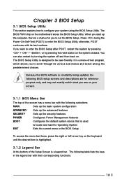
... To access the menu bar items, press the right or left arrow key on your system using the BIOS Setup Utility. Because the BIOS software is constantly being updated, the following BIOS setup screens and descriptions are for you see on the keyboard until the desired item is highlighted. 3.1.2 Legend... after POST, restart the system by pressing + + , or by turning the system off and then back on the motherboard stores the BIOS Setup Utility. The following selections: MAIN Sets up the basic system configuration ADVANCED Sets up the advanced features SECURITY Sets up the computer, ...
... To access the menu bar items, press the right or left arrow key on your system using the BIOS Setup Utility. Because the BIOS software is constantly being updated, the following BIOS setup screens and descriptions are for you see on the keyboard until the desired item is highlighted. 3.1.2 Legend... after POST, restart the system by pressing + + , or by turning the system off and then back on the motherboard stores the BIOS Setup Utility. The following selections: MAIN Sets up the basic system configuration ADVANCED Sets up the advanced features SECURITY Sets up the computer, ...
User Manual
Page 19
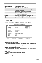
... setup items to configure IDE devices. 19 Floppy Drives Use this to default value Saves changes and exits Setup 3.2 Main Menu When you enter the BIOS Setup Utility, the following screen appears. Navigation Key(s) / / + / Function Description Displays the General Help Screen Jumps to the Exit menu or returns to...2099). System Time [Hour:Minute:Second] Set the system to move between the Hour, Minute and Second fields. Dec Day: 01 - 31 Year: 1980 - 2099 P4I45G BIOS P1.00 Pentium (R) 4 Family CPU 2100 MHz 512 KB F23 / 08 127 MB + 1 MB Share Memory 128 MB / 133 MHz (DDR 266) None ...
... setup items to configure IDE devices. 19 Floppy Drives Use this to default value Saves changes and exits Setup 3.2 Main Menu When you enter the BIOS Setup Utility, the following screen appears. Navigation Key(s) / / + / Function Description Displays the General Help Screen Jumps to the Exit menu or returns to...2099). System Time [Hour:Minute:Second] Set the system to move between the Hour, Minute and Second fields. Dec Day: 01 - 31 Year: 1980 - 2099 P4I45G BIOS P1.00 Pentium (R) 4 Family CPU 2100 MHz 512 KB F23 / 08 127 MB + 1 MB Share Memory 128 MB / 133 MHz (DDR 266) None ...
User Manual
Page 20
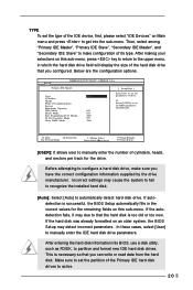
... HDD parameters automatically. TYPE To set the type of the IDE device, first, please select "IDE Devices" on Main menu and press to get into BIOS, use a disk utility, such as FDISK, to partition and format new IDE hard disk drives. VERSION 3.31a Primary IDE Master: [ Setup Help ] Type...new. After entering the hard disk information into the sub-menu. Main AMIBIOS SETUP UTILITY - After making your selections on an older system, the BIOS Setup may due to make sure you configured. Make sure to set the parameters of drive, Or Select [AUTO] to automatically detect hard disk ...
... HDD parameters automatically. TYPE To set the type of the IDE device, first, please select "IDE Devices" on Main menu and press to get into BIOS, use a disk utility, such as FDISK, to partition and format new IDE hard disk drives. VERSION 3.31a Primary IDE Master: [ Setup Help ] Type...new. After entering the hard disk information into the sub-menu. Main AMIBIOS SETUP UTILITY - After making your selections on an older system, the BIOS Setup may due to make sure you configured. Make sure to set the parameters of drive, Or Select [AUTO] to automatically detect hard disk ...
User Manual
Page 21
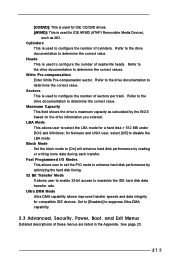
... the hard disk timing. 32 Bit Transfer Mode It allows user to enable 32-bit access to [On] will enhance hard disk performance by the BIOS based on the drive information you entered. Heads This is used to configure the number of read/write heads. Cylinders This is used to configure...
... the hard disk timing. 32 Bit Transfer Mode It allows user to enable 32-bit access to [On] will enhance hard disk performance by the BIOS based on the drive information you entered. Heads This is used to configure the number of read/write heads. Cylinders This is used to configure...
User Manual
Page 23
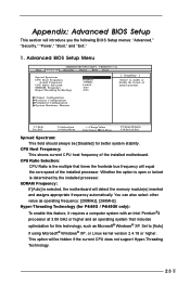
...assigns appropriate frequency automatically. SDRAM Frequency: If [Auto] is determined by the installed processor. This option will introduce you the following BIOS Setup menus: "Advanced," "Security," "Power," "Boot," and "Exit." 1. VERSION 3.31a Security Power Boot Exit Spread Spectrum ...-Threading Technology (for better system stability. Appendix: Advanced BIOS Setup This section will be [Disabled] for P4i45G / P4i45GV only): To enable this technology, such as operating frequency: [200MHz], [266MHz]. Advanced BIOS Setup Menu Main Advanced AMIBIOS SETUP UTILITY - Whether the...
...assigns appropriate frequency automatically. SDRAM Frequency: If [Auto] is determined by the installed processor. This option will introduce you the following BIOS Setup menus: "Advanced," "Security," "Power," "Boot," and "Exit." 1. VERSION 3.31a Security Power Boot Exit Spread Spectrum ...-Threading Technology (for better system stability. Appendix: Advanced BIOS Setup This section will be [Disabled] for P4i45G / P4i45GV only): To enable this technology, such as operating frequency: [200MHz], [266MHz]. Advanced BIOS Setup Menu Main Advanced AMIBIOS SETUP UTILITY - Whether the...
User Manual
Page 27
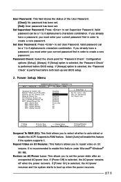
... this feature if the system supports it. If you already have a password, you to 6 alphanumeric characters combination. If [Power On] is performed before BIOS setup. Valid password can be a 1 to repost video on AC / Power Loss Ring-In Power On PCI Devices Power On PS / 2 keyboard ... Menu +/-:Change Values Enter:Select Sub-Menu F9:Setup Defaults F10:Save & Exit Suspend To RAM (S3): This field allows you to boot up and BIOS setup. 3. Valid password can be a 1 to create a new password. Password Check: Select the check point for "Password Check". If [Setup] option is...
... this feature if the system supports it. If you already have a password, you to 6 alphanumeric characters combination. If [Power On] is performed before BIOS setup. Valid password can be a 1 to repost video on AC / Power Loss Ring-In Power On PCI Devices Power On PS / 2 keyboard ... Menu +/-:Change Values Enter:Select Sub-Menu F9:Setup Defaults F10:Save & Exit Suspend To RAM (S3): This field allows you to boot up and BIOS setup. 3. Valid password can be a 1 to create a new password. Password Check: Select the check point for "Password Check". If [Setup] option is...
User Manual
Page 29
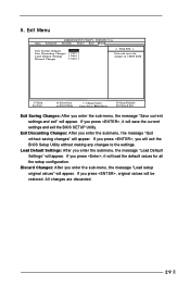
...original values will be restored. If you enter the sub-menu, the message "Load setup original values" will save the current settings and exit the BIOS SETUP Utility. F1:Help Esc:Exit :Select Item :Select Menu +/-:Change Values Enter:Select Sub-Menu F9:Setup Defaults F10:Save & Exit Exit ...Saving Changes: After you press , it will appear. Exit Discarding Changes: After you will exit the BIOS Setup Utility without saving changes" will appear. If you enter the sub-menu, the message "Save current settings and exit" will appear. If you...
...original values will be restored. If you enter the sub-menu, the message "Load setup original values" will save the current settings and exit the BIOS SETUP Utility. F1:Help Esc:Exit :Select Item :Select Menu +/-:Change Values Enter:Select Sub-Menu F9:Setup Defaults F10:Save & Exit Exit ...Saving Changes: After you press , it will appear. Exit Discarding Changes: After you will exit the BIOS Setup Utility without saving changes" will appear. If you enter the sub-menu, the message "Save current settings and exit" will appear. If you...


