User Manual
Page 3
... Configuration 31 3.4 Hardware Health Event Monitoring Screen 32 3.5 Boot Screen 32 3.5.1 Boot Settings Configuration 33 3.6 Security Screen 33 3.7 Exit Screen 34 3 Introduction 5 1.1 Package Contents 5 1.2 Specifications 6 1.3 Motherboard Layout 8 1.4 ASRock I/O Plus 9 TM 2. Contents 1.
... Configuration 31 3.4 Hardware Health Event Monitoring Screen 32 3.5 Boot Screen 32 3.5.1 Boot Settings Configuration 33 3.6 Security Screen 33 3.7 Exit Screen 34 3 Introduction 5 1.1 Package Contents 5 1.2 Specifications 6 1.3 Motherboard Layout 8 1.4 ASRock I/O Plus 9 TM 2. Contents 1.
User Manual
Page 5
... endurance. Introduction Thank you for a 3.5-in , 24.4 cm x 20.3 cm) ASRock P4VM800 Quick Installation Guide ASRock P4VM800 Support CD One 80-conductor Ultra ATA 66/100/133 IDE Ribbon Cable One Ribbon Cable for purchasing ASRock P4VM800 motherboard, a reliable motherboard produced under ASRock's consistently stringent quality control. Because the motherboard specifications and the BIOS software might be updated, the content...
... endurance. Introduction Thank you for a 3.5-in , 24.4 cm x 20.3 cm) ASRock P4VM800 Quick Installation Guide ASRock P4VM800 Support CD One 80-conductor Ultra ATA 66/100/133 IDE Ribbon Cable One Ribbon Cable for purchasing ASRock P4VM800 motherboard, a reliable motherboard produced under ASRock's consistently stringent quality control. Because the motherboard specifications and the BIOS software might be updated, the content...
User Manual
Page 7
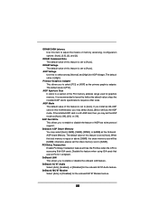
...system or damage the CPU. 7 About the setting of this motherboard offers stepless control, it back again. Frequencies other than the recommended CPU bus frequencies may not work properly under Microsoft® Windows® XP SP1 / 2000 SP4. ASRock I/O PlusTM: 1 PS/2 mouse port, 1 PS/2 keyboard port..., 1 VGA port, 1 parallel port: ECP/EPP support, 6 ready-to-use a 3.3V AGP card on the motherboard functions properly and unplug the power cord, then plug it is...
...system or damage the CPU. 7 About the setting of this motherboard offers stepless control, it back again. Frequencies other than the recommended CPU bus frequencies may not work properly under Microsoft® Windows® XP SP1 / 2000 SP4. ASRock I/O PlusTM: 1 PS/2 mouse port, 1 PS/2 keyboard port..., 1 VGA port, 1 parallel port: ECP/EPP support, 6 ready-to-use a 3.3V AGP card on the motherboard functions properly and unplug the power cord, then plug it is...

User Manual
Page 8
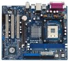
...) 27 Chassis Fan Connector (CHA_FAN1) 28 Shared USB 2.0 Header (USB4_5, Blue) 29 North Bridge Controller 30 CPU Fan Connector (CPU_FAN1) 8 1.3 Motherboard Layout PS2 Keyboard 1 23 4 20.3cm (8.0 in) PS2 Mouse 1 PS2_USB_PWR1 ATX12V1 56 1 IR1 Super I/O 4Mb BIOS PARALLEL PORT PGA478 VGA1 30...PHY VIA P4M800 Chipset 5.1CH 1 AUDIO1 CMOS Battery JR1 JL1 CLRCMOS1 CD1 AUX1 Audio CODEC AMR1 AGP 8X 1.5V_AGP1 ATA133 IDE1 IDE2 PCI 1 ` P4VM800 PCI 2 USB2.0 PCI 3 1 COM1 VIA VT8237R SATA 1 USB67 PANEL 1 PLED PWRBTN 1 1 SPEAKER1 HDLED RESET SATA2 SATA1 Prescott 800 DDR400 ...
...) 27 Chassis Fan Connector (CHA_FAN1) 28 Shared USB 2.0 Header (USB4_5, Blue) 29 North Bridge Controller 30 CPU Fan Connector (CPU_FAN1) 8 1.3 Motherboard Layout PS2 Keyboard 1 23 4 20.3cm (8.0 in) PS2 Mouse 1 PS2_USB_PWR1 ATX12V1 56 1 IR1 Super I/O 4Mb BIOS PARALLEL PORT PGA478 VGA1 30...PHY VIA P4M800 Chipset 5.1CH 1 AUDIO1 CMOS Battery JR1 JL1 CLRCMOS1 CD1 AUX1 Audio CODEC AMR1 AGP 8X 1.5V_AGP1 ATA133 IDE1 IDE2 PCI 1 ` P4VM800 PCI 2 USB2.0 PCI 3 1 COM1 VIA VT8237R SATA 1 USB67 PANEL 1 PLED PWRBTN 1 1 SPEAKER1 HDLED RESET SATA2 SATA1 Prescott 800 DDR400 ...

User Manual
Page 10
...P4VM800 is detached from the wall socket before you install motherboard components or change any component, place it . Pre-installation Precautions Take note of your chassis to static electricity, NEVER place your motherboard directly on a grounded antistatic pad or in , 24.4 cm x 20.3 cm) motherboard. Whenever you uninstall any motherboard... precautions before you handle components. 3. 2. Before you install or remove any component. 2. To avoid damaging the motherboard components due to ensure that the power is switched off or the power cord is a Micro ATX form factor ...
...P4VM800 is detached from the wall socket before you install motherboard components or change any component, place it . Pre-installation Precautions Take note of your chassis to static electricity, NEVER place your motherboard directly on a grounded antistatic pad or in , 24.4 cm x 20.3 cm) motherboard. Whenever you uninstall any motherboard... precautions before you handle components. 3. 2. Before you install or remove any component. 2. To avoid damaging the motherboard components due to ensure that the power is switched off or the power cord is a Micro ATX form factor ...

User Manual
Page 11
... to support Intel® Pentium® 4 / Celeron® CPU. For proper installation, please kindly refer to the instruction manuals of CPU Fan and Heatsink This motherboard adopts 478-pin CPU socket to The Socket Marked Corner STEP 4: Push Down And Lock The Socket Lever 2.2 Installation of the CPU fan and the...
... to support Intel® Pentium® 4 / Celeron® CPU. For proper installation, please kindly refer to the instruction manuals of CPU Fan and Heatsink This motherboard adopts 478-pin CPU socket to The Socket Marked Corner STEP 4: Push Down And Lock The Socket Lever 2.2 Installation of the CPU fan and the...

User Manual
Page 12
... place and the DIMM is properly seated. 12 Step 2. Unlock a DIMM slot by pressing the retaining clips outward. 2.3 Installation of Memory Modules (DIMM) P4VM800 motherboard provides two 184-pin DDR (Double Data Rate) DIMM slots. Align a DIMM on the slot such that the notch on the DIMM matches the break... on the slot. Step 3. Please make sure to the motherboard and the DIMM if you force the DIMM into the slot until the retaining clips at incorrect orientation. It will cause permanent damage to disconnect...
... place and the DIMM is properly seated. 12 Step 2. Unlock a DIMM slot by pressing the retaining clips outward. 2.3 Installation of Memory Modules (DIMM) P4VM800 motherboard provides two 184-pin DDR (Double Data Rate) DIMM slots. Align a DIMM on the slot such that the notch on the DIMM matches the break... on the slot. Step 3. Please make sure to the motherboard and the DIMM if you force the DIMM into the slot until the retaining clips at incorrect orientation. It will cause permanent damage to disconnect...
User Manual
Page 13
... Remove the system unit cover (if your AGP card, please check with the slot and press firmly until the card is completely seated on P4VM800 motherboard. Remove the bracket facing the slot that have the 32-bit PCI interface. Step 4. Align the card connector with the AGP card vendors...AGP Slots) There are used to insert an ASRock MR card with screws. AGP slot: The AGP slot is unplugged. The ASRock AGP slot has a special design of this motherboard! Installing an expansion card Step 1. Please read the documentation of your motherboard is used to install expansion cards that you ...
... Remove the system unit cover (if your AGP card, please check with the slot and press firmly until the card is completely seated on P4VM800 motherboard. Remove the bracket facing the slot that have the 32-bit PCI interface. Step 4. Align the card connector with the AGP card vendors...AGP Slots) There are used to insert an ASRock MR card with screws. AGP slot: The AGP slot is unplugged. The ASRock AGP slot has a special design of this motherboard! Installing an expansion card Step 1. Please read the documentation of your motherboard is used to install expansion cards that you ...

User Manual
Page 15
...) connectors support SATA data cables for the details. The current SATA interface allows up to the SATA hard disk or the SATA connector on this motherboard, please set the IDE device as "Master". FDD Connector (33-pin FLOPPY1) (see p.8, No. 9) Pin1 FLOPPY1 the red-striped side to ...for internal storage devices. Besides, to Pin1 Note: Make sure the red-striped side of the cable is plugged into Pin1 side of the motherboard! Placing jumper caps over these headers and connectors. Do NOT place jumper caps over the headers and connectors will cause permanent damage of the ...
...) connectors support SATA data cables for the details. The current SATA interface allows up to the SATA hard disk or the SATA connector on this motherboard, please set the IDE device as "Master". FDD Connector (33-pin FLOPPY1) (see p.8, No. 9) Pin1 FLOPPY1 the red-striped side to ...for internal storage devices. Besides, to Pin1 Note: Make sure the red-striped side of the cable is plugged into Pin1 side of the motherboard! Placing jumper caps over these headers and connectors. Do NOT place jumper caps over the headers and connectors will cause permanent damage of the ...
User Manual
Page 18
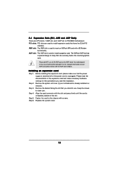
... for RAID configuration, it cannot perform Hot Plug if the OS has been installed into the drive bays of the SATA data cable to the motherboard's SATA connector. However, please note that supports Serial ATA (SATA) hard disks and RAID functions. If the SATA HDDs are built as RAID1...SATA HDD. STEP 3: Connect one end of the SATA data cable to the SATA hard disk. 2.8 Hot Plug and Hot Swap Functions for SATA HDDs P4VM800 motherboard supports Hot Plug and Hot Swap functions for SATA Devices. STEP 4: Connect the other end of your chassis. 2.7 Serial ATA (SATA) Hard Disks ...
... for RAID configuration, it cannot perform Hot Plug if the OS has been installed into the drive bays of the SATA data cable to the motherboard's SATA connector. However, please note that supports Serial ATA (SATA) hard disks and RAID functions. If the SATA HDDs are built as RAID1...SATA HDD. STEP 3: Connect one end of the SATA data cable to the SATA hard disk. 2.8 Hot Plug and Hot Swap Functions for SATA HDDs P4VM800 motherboard supports Hot Plug and Hot Swap functions for SATA Devices. STEP 4: Connect the other end of your chassis. 2.7 Serial ATA (SATA) Hard Disks ...

User Manual
Page 21
... device to enter the BIOS SETUP UTILITY after POST, restart the system by pressing + + , or by turning the system off and then back on the motherboard stores the BIOS SETUP UTILITY. Please press during the Power-On-Self-Test (POST) to enter the BIOS SETUP UTILITY, otherwise, POST will continue with...
... device to enter the BIOS SETUP UTILITY after POST, restart the system by pressing + + , or by turning the system off and then back on the motherboard stores the BIOS SETUP UTILITY. Please press during the Power-On-Self-Test (POST) to enter the BIOS SETUP UTILITY, otherwise, POST will continue with...
User Manual
Page 23
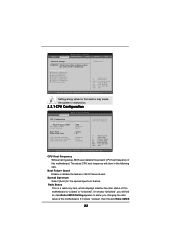
... spectrum feature. If it shows "Locked", then the item Ratio CMOS 23 Boot Failure Guard Enable or disable the feature of this motherboard. If it shows "Unlocked", you changing the ratio value of Boot Failure Guard. The actual CPU host frequency will find an item... Ratio CMOS Setting appears to allow you will show in this motherboard is a read-only item, which displays whether the ratio status of this motherboard. Ratio Status This is "Locked" or "Unlocked". CPU Configuration Chipset Configuration ACPI Configuration IDE Configuration...
... spectrum feature. If it shows "Locked", then the item Ratio CMOS 23 Boot Failure Guard Enable or disable the feature of this motherboard. If it shows "Unlocked", you changing the ratio value of Boot Failure Guard. The actual CPU host frequency will find an item... Ratio CMOS Setting appears to allow you will show in this motherboard is a read-only item, which displays whether the ratio status of this motherboard. Ratio Status This is "Locked" or "Unlocked". CPU Configuration Chipset Configuration ACPI Configuration IDE Configuration...
User Manual
Page 24
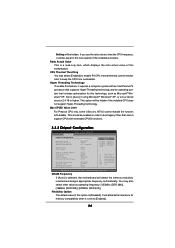
... item, which displays the ratio actual value of the installed processor. It will allow better tolerance for this motherboard. If you use the ratio value to time the CPU frequency, it is selected, the motherboard will detect the memory module(s) inserted and assigns appropriate frequency automatically. Max CPUID Value Limit For Prescott...
... item, which displays the ratio actual value of the installed processor. It will allow better tolerance for this motherboard. If you use the ratio value to time the CPU frequency, it is selected, the motherboard will detect the memory module(s) inserted and assigns appropriate frequency automatically. Max CPUID Value Limit For Prescott...
User Manual
Page 25
...# Latency Use this feature when using ISA cards that are not PCI 2.1 compliant. DRAM Voltage The default value of memory accessing. AGP Voltage Use this motherboard, you may set to select [PCI] or [AGP] as the Onboard AGP share Memory. AGP Aperture Size It refers to [32MB]. If the installed AGP...
...# Latency Use this feature when using ISA cards that are not PCI 2.1 compliant. DRAM Voltage The default value of memory accessing. AGP Voltage Use this motherboard, you may set to select [PCI] or [AGP] as the Onboard AGP share Memory. AGP Aperture Size It refers to [32MB]. If the installed AGP...

User Manual
Page 32
...] [2nd Floppy Device] [3rd Floppy Device] Configure Settings during System Boot. Select Screen Select Item Enter Go to monitor the status of the CPU temperature, motherboard temperature, CPU fan speed, chassis fan speed, and the critical voltage. 3.4 Hardware Health Event Monitoring Screen In this section, it allows you to configure the...
...] [2nd Floppy Device] [3rd Floppy Device] Configure Settings during System Boot. Select Screen Select Item Enter Go to monitor the status of the CPU temperature, motherboard temperature, CPU fan speed, chassis fan speed, and the critical voltage. 3.4 Hardware Health Event Monitoring Screen In this section, it allows you to configure the...

User Manual
Page 35
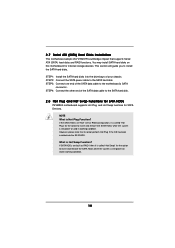
...the CD into your computer. or you need to contact ASRock or want to know more information. 4.2 Support CD Information The Support CD that came with the motherboard contains necessary drivers and useful utilities that the motherboard supports. The CD automatically displays the Main Menu if "... devices. Click on the file "ASSETUP.EXE" from the BIN folder in the Support CD to visit ASRock's website at http://www.asrock.com; 4. Software Support 4.1 Install Operating System This motherboard supports various Microsoft® Windows® operating systems: 98 SE / ME / 2000 / XP. If...
...the CD into your computer. or you need to contact ASRock or want to know more information. 4.2 Support CD Information The Support CD that came with the motherboard contains necessary drivers and useful utilities that the motherboard supports. The CD automatically displays the Main Menu if "... devices. Click on the file "ASSETUP.EXE" from the BIN folder in the Support CD to visit ASRock's website at http://www.asrock.com; 4. Software Support 4.1 Install Operating System This motherboard supports various Microsoft® Windows® operating systems: 98 SE / ME / 2000 / XP. If...


