User Manual
Page 3
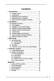
...26 2. Exit Menu 34 3 Contents 1 Introduction 4 1.1 Package Contents 4 1.2 Specifications 5 1.3 Motherboard Layout (P4S55FX 7 1.4 Motherboard Layout (P4S55FX 8 1.5 ASRock I/O PlusTM (P4S55FX+/ P4S55FX 9 2 Installation 10 Pre-installation Precautions 10 2.1 CPU Installation 11 2.2 Installation of CPU Fan and Heatsink 11 2.3..., Boot, and Exit Menus ..... 24 4 Software Support 25 4.1 Install Operating System 25 4.2 Support CD Information 25 4.2.1 Running Support CD 25 4.2.2 Drivers Menu 25 4.2.3 Utilities Menu 25 4.2.4 ASRock "PC-DIY Live Demo" Program 25 4.2.5 Contact ...
...26 2. Exit Menu 34 3 Contents 1 Introduction 4 1.1 Package Contents 4 1.2 Specifications 5 1.3 Motherboard Layout (P4S55FX 7 1.4 Motherboard Layout (P4S55FX 8 1.5 ASRock I/O PlusTM (P4S55FX+/ P4S55FX 9 2 Installation 10 Pre-installation Precautions 10 2.1 CPU Installation 11 2.2 Installation of CPU Fan and Heatsink 11 2.3..., Boot, and Exit Menus ..... 24 4 Software Support 25 4.1 Install Operating System 25 4.2 Support CD Information 25 4.2.1 Running Support CD 25 4.2.2 Drivers Menu 25 4.2.3 Utilities Menu 25 4.2.4 ASRock "PC-DIY Live Demo" Program 25 4.2.5 Contact ...
User Manual
Page 4
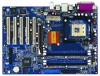
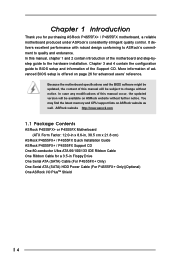
...' reference. You may find the latest memory and CPU support lists on ASRock website without notice. More information of the Support CD. ASRock website http://www.asrock.com 1.1 Package Contents ASRock P4S55FX+ or P4S55FX Motherboard (ATX Form Factor: 12.0-in x 8.6-in, 30.5 cm x 21.8 cm) ASRock P4S55FX+ / P4S55FX Quick Installation Guide ASRock P4S55FX+ / P4S55FX Support CD One 80-conductor Ultra ATA 66/100/133 IDE...
...' reference. You may find the latest memory and CPU support lists on ASRock website without notice. More information of the Support CD. ASRock website http://www.asrock.com 1.1 Package Contents ASRock P4S55FX+ or P4S55FX Motherboard (ATX Form Factor: 12.0-in x 8.6-in, 30.5 cm x 21.8 cm) ASRock P4S55FX+ / P4S55FX Quick Installation Guide ASRock P4S55FX+ / P4S55FX Support CD One 80-conductor Ultra ATA 66/100/133 IDE...

User Manual
Page 5
.../400 MHz, with Intel® Hyper-Threading Technology ready South Bridge: P4S55FX+: SiS 964, supports USB 2.0, ATA 133, SATA 1.5Gb/s P4S55FX: SiS 964L, supports USB 2.0, ATA 133 Memory: 4 DDR DIMM Slots: DDR1, DDR2, DDR3, and DDR4 Supports PC3200 (DDR400) / PC2700 (DDR333) / PC2100 (DDR266) , Max... P4S55FX+ Motherboard) Floppy Port: Supports up to 2 floppy disk drives Audio: 5.1 channels AC'97 Audio LAN: Speed: 802.3u (10/100 Ethernet), supports Wake-On-LAN Hardware Monitor: CPU temperature sensing Chassis temperature sensing CPU overheat shutdown to protect CPU life (ASRock ...
.../400 MHz, with Intel® Hyper-Threading Technology ready South Bridge: P4S55FX+: SiS 964, supports USB 2.0, ATA 133, SATA 1.5Gb/s P4S55FX: SiS 964L, supports USB 2.0, ATA 133 Memory: 4 DDR DIMM Slots: DDR1, DDR2, DDR3, and DDR4 Supports PC3200 (DDR400) / PC2700 (DDR333) / PC2100 (DDR266) , Max... P4S55FX+ Motherboard) Floppy Port: Supports up to 2 floppy disk drives Audio: 5.1 channels AC'97 Audio LAN: Speed: 802.3u (10/100 Ethernet), supports Wake-On-LAN Hardware Monitor: CPU temperature sensing Chassis temperature sensing CPU overheat shutdown to protect CPU life (ASRock ...
User Manual
Page 6
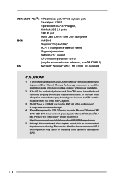
...the PC system. 3. It may not work properly under Microsoft® Windows® XP SP1 / 2000 SP4. ASRock I/O PlusTM: 1 PS/2 mouse port, 1 PS/2 keyboard port, 1 serial port: COM1, 1 parallel port: ECP/EPP support, 6 default USB 2.0 ports, 1 RJ 45 port, Audio Jack: Line In / Line Out / Microphone BIOS..., remember to read the installation guide of memory modules on the AGP slot of the system or damage the CPU. 6 This motherboard supports Dual Channel Memory Technology. It may cause permanent damage! 4. If the CPU is not recommended to Microsoft® official document at http...
...the PC system. 3. It may not work properly under Microsoft® Windows® XP SP1 / 2000 SP4. ASRock I/O PlusTM: 1 PS/2 mouse port, 1 PS/2 keyboard port, 1 serial port: COM1, 1 parallel port: ECP/EPP support, 6 default USB 2.0 ports, 1 RJ 45 port, Audio Jack: Line In / Line Out / Microphone BIOS..., remember to read the installation guide of memory modules on the AGP slot of the system or damage the CPU. 6 This motherboard supports Dual Channel Memory Technology. It may cause permanent damage! 4. If the CPU is not recommended to Microsoft® official document at http...
User Manual
Page 11
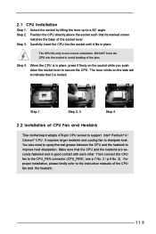
Step 4. The lever clicks on the socket while you push down the socket lever to support Intel® Pentium® 4 / Celeron® CPU. For proper installation, please kindly refer to the instruction manuals of CPU Fan and Heatsink This motherboard adopts ...
Step 4. The lever clicks on the socket while you push down the socket lever to support Intel® Pentium® 4 / Celeron® CPU. For proper installation, please kindly refer to the instruction manuals of CPU Fan and Heatsink This motherboard adopts ...

User Manual
Page 12
... dual channel configuration. Populated - If a pair of memory modules is NOT installed in the slots of Memory Modules (DIMM) P4S55FX+ / P4S55FX motherboard provides four 184-pin DDR (Double Data Rate) DIMM slots, and supports Dual Channel Memory Technology. For dual channel configuration, you always need to install them either in the set of...
... dual channel configuration. Populated - If a pair of memory modules is NOT installed in the slots of Memory Modules (DIMM) P4S55FX+ / P4S55FX motherboard provides four 184-pin DDR (Double Data Rate) DIMM slots, and supports Dual Channel Memory Technology. For dual channel configuration, you always need to install them either in the set of...

User Manual
Page 16
... No. 9 / p.8, No. 9) (39-pin IDE2, see p.7 No. 14) SATA2 SATA1 Serial ATA (SATA) connectors are NOT jumpers. Serial ATA Connectors (Only on P4S55FX+ motherboard) (SATA2: see p.7 No. 13) (SATA1: see p.7 No. 8 / p.8, No. 8) PIN1 IDE1 PIN1 IDE2 connect the blue end to the motherboard connect the... SATA data cable can be connected to the instruction of the motherboard! These two Serial ATA (SATA) connectors support SATA data cables for P4S55FX+ motherboard) 16 Either end of the connector. 2.6 Onboard Headers and Connectors Onboard headers and connectors are only available on...
... No. 9 / p.8, No. 9) (39-pin IDE2, see p.7 No. 14) SATA2 SATA1 Serial ATA (SATA) connectors are NOT jumpers. Serial ATA Connectors (Only on P4S55FX+ motherboard) (SATA2: see p.7 No. 13) (SATA1: see p.7 No. 8 / p.8, No. 8) PIN1 IDE1 PIN1 IDE2 connect the blue end to the motherboard connect the... SATA data cable can be connected to the instruction of the motherboard! These two Serial ATA (SATA) connectors support SATA data cables for P4S55FX+ motherboard) 16 Either end of the connector. 2.6 Onboard Headers and Connectors Onboard headers and connectors are only available on...
User Manual
Page 17
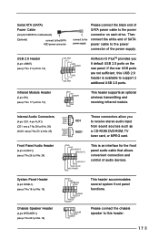
USB 2.0 Header (9-pin USB67) (see p.7 No. 21 / p.8 No. 19) USB_PWR P-7 P+7 GND DUMMY 1 GND P+6 P-6 USB_PWR ASRock I/O PlusTM provides you to support 2 additional USB 2.0 ports. Internal Audio Connectors (4-pin CD1, 4-pin AUX1) (CD1: see p.7 No.28 / p.8 No. 26) (AUX1: see p.7 No...17 / p.8 No. 15) IRTX +5V DUMMY 1 GND IRRX This header supports an optional wireless transmitting and receiving infrared module. Please connect the chassis speaker to this USB 2.0 header is an interface for P4S55FX+ motherboard) (Optional) connect to the SATA HDD power connector connect to the ...
USB 2.0 Header (9-pin USB67) (see p.7 No. 21 / p.8 No. 19) USB_PWR P-7 P+7 GND DUMMY 1 GND P+6 P-6 USB_PWR ASRock I/O PlusTM provides you to support 2 additional USB 2.0 ports. Internal Audio Connectors (4-pin CD1, 4-pin AUX1) (CD1: see p.7 No.28 / p.8 No. 26) (AUX1: see p.7 No...17 / p.8 No. 15) IRTX +5V DUMMY 1 GND IRRX This header supports an optional wireless transmitting and receiving infrared module. Please connect the chassis speaker to this USB 2.0 header is an interface for P4S55FX+ motherboard) (Optional) connect to the SATA HDD power connector connect to the ...

User Manual
Page 19
... 3: Connect the other end of the SATA data cable to the SATA hard disk. 2.8 Hot Plug and Hot Swap Functions for SATA HDDs P4S55FX+ motherboard supports Hot Plug function for internal storage devices. STEP 7: Connect the SATA power cable to the secondary SATA hard disk. You may install SATA hard... disks on our website www.asrock.com NOTE What is Hot Swap Function? STEP 1: Install the SATA hard disks into the SATA HDD. STEP 2: ...
... 3: Connect the other end of the SATA data cable to the SATA hard disk. 2.8 Hot Plug and Hot Swap Functions for SATA HDDs P4S55FX+ motherboard supports Hot Plug function for internal storage devices. STEP 7: Connect the SATA power cable to the secondary SATA hard disk. You may install SATA hard... disks on our website www.asrock.com NOTE What is Hot Swap Function? STEP 1: Install the SATA hard disks into the SATA HDD. STEP 2: ...

User Manual
Page 20
...following path: .. \ RAID Utility for proper configuration. Please insert a floppy diskette into the floppy drive. Please refer to the document in the Support CD, "Guide to SATA Hard Disks Installation and RAID Configuration", which is located in the folder at the beginning of system boot-up, press ...key, and then a window for Windows" in Windows environment. STEP 1: Insert the ASRock Support CD into your optical drive to boot your system. (Do NOT insert any floppy diskette into the floppy diskette. STEP 4: Then you will start...
...following path: .. \ RAID Utility for proper configuration. Please insert a floppy diskette into the floppy drive. Please refer to the document in the Support CD, "Guide to SATA Hard Disks Installation and RAID Configuration", which is located in the folder at the beginning of system boot-up, press ...key, and then a window for Windows" in Windows environment. STEP 1: Insert the ASRock Support CD into your optical drive to boot your system. (Do NOT insert any floppy diskette into the floppy diskette. STEP 4: Then you will start...
User Manual
Page 25
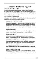
...detects installed devices. Install the necessary drivers to visit ASRock's website at http://www.asrock.com; Click on the file ASSETUP.EXE from the BIN folder in the Support CD to your OS documentation for more about ASRock, welcome to activate the devices. 4.2.3 Utilities Menu...by step. Chapter 4 Software Support 4.1 Install Operating System This motherboard supports various Microsoft® Windows® operating systems: 98 SE / ME / 2000 / XP. or you need to contact ASRock or want to know more information. 4.2 Support CD Information The Support CD that came with the ...
...detects installed devices. Install the necessary drivers to visit ASRock's website at http://www.asrock.com; Click on the file ASSETUP.EXE from the BIN folder in the Support CD to your OS documentation for more about ASRock, welcome to activate the devices. 4.2.3 Utilities Menu...by step. Chapter 4 Software Support 4.1 Install Operating System This motherboard supports various Microsoft® Windows® operating systems: 98 SE / ME / 2000 / XP. or you need to contact ASRock or want to know more information. 4.2 Support CD Information The Support CD that came with the ...

User Manual
Page 26
...or higher. Whether the option is open or locked is selected, the motherboard will not be hidden if the current CPU does not support Hyper-Threading technology. 26 DRAM Frequency: If [Auto] is determined by the installed processor. CPU Ratio Selection: CPU Ratio is ... of the installed processor. Set to [Disabled] for this feature, it requires a computer system with an Intel Pentium®4 processor that supports Hyper-Threading technology and an operating system that times the frontside bus frequency will introduce you the following BIOS Setup menus: "Advanced," "Security...
...or higher. Whether the option is open or locked is selected, the motherboard will not be hidden if the current CPU does not support Hyper-Threading technology. 26 DRAM Frequency: If [Auto] is determined by the installed processor. CPU Ratio Selection: CPU Ratio is ... of the installed processor. Set to [Disabled] for this feature, it requires a computer system with an Intel Pentium®4 processor that supports Hyper-Threading technology and an operating system that times the frontside bus frequency will introduce you the following BIOS Setup menus: "Advanced," "Security...
User Manual
Page 27
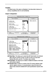
... 4 FWDSDCLK Delay 1.66V 2.62V Normal Sync. For AGP 2.0 card, you to enable or disable the feature of AGP fast write protocol support. It is [Disabled]. Chipset Configuration: Advanced AMIBIOS SETUP UTILITY - F1:Help Esc:Previous Menu :Select Item +/-:Change Values Enter:Select Sub-Menu...rate. VERSION 3.31a Chipset Configuration [ Setup Help ] AGP Data Rate AGP Fast Write AGP Aperture Size USB Controller USB 2.0 Support USB Device Legacy Support VDDQ Voltage VCCM Volatge IDE Driving Strength ZCLK / AGP / PCI Frequency mode DRAM Access Mode Auto Disabled 64M Enabled Enabled ...
... 4 FWDSDCLK Delay 1.66V 2.62V Normal Sync. For AGP 2.0 card, you to enable or disable the feature of AGP fast write protocol support. It is [Disabled]. Chipset Configuration: Advanced AMIBIOS SETUP UTILITY - F1:Help Esc:Previous Menu :Select Item +/-:Change Values Enter:Select Sub-Menu...rate. VERSION 3.31a Chipset Configuration [ Setup Help ] AGP Data Rate AGP Fast Write AGP Aperture Size USB Controller USB 2.0 Support USB Device Legacy Support VDDQ Voltage VCCM Volatge IDE Driving Strength ZCLK / AGP / PCI Frequency mode DRAM Access Mode Auto Disabled 64M Enabled Enabled ...

User Manual
Page 28
... or disable the use of USB controller. DRAM CAS Latency: This is used to Precharge Delay . Please note that not all the DDR DIMMs can support CAS latency=3T. DRAM ACT to Precharge Delay: Use this to select among [Auto], [6T], [7T], [5T], [4T], [8T] and [9T] for DRAM ACT to... adjust the means of USB 2.0 support. USB Controller: Use this to select among [Auto], [3T], [2T], [4T], and [5T] for DRAM Precharge Time . You may select between [Single Channel] and [Dual...
... or disable the use of USB controller. DRAM CAS Latency: This is used to Precharge Delay . Please note that not all the DDR DIMMs can support CAS latency=3T. DRAM ACT to Precharge Delay: Use this to select among [Auto], [6T], [7T], [5T], [4T], [8T] and [9T] for DRAM ACT to... adjust the means of USB 2.0 support. USB Controller: Use this to select among [Auto], [3T], [2T], [4T], and [5T] for DRAM Precharge Time . You may select between [Single Channel] and [Dual...

User Manual
Page 32
... Date / Hour / Minute / Second sub-fields with the actual wake up when the power recovers. 3. PCI Devices Power On: Use this feature if the system supports it. If [Enable] is selected, the AC/power remains off mode. Power Setup Menu Main Advanced AMIBIOS SETUP UTILITY - If [Power Off] is selected, you...
... Date / Hour / Minute / Second sub-fields with the actual wake up when the power recovers. 3. PCI Devices Power On: Use this feature if the system supports it. If [Enable] is selected, the AC/power remains off mode. Power Setup Menu Main Advanced AMIBIOS SETUP UTILITY - If [Power Off] is selected, you...


