
User Manual
Page 3
... 5 1.1 Package Contents 5 1.2 Specifications 6 1.3 Supported AGP VGA Cards Lists for AGI Slot 8 1.4 Supported PCI Express VGA Cards Lists for AGI Express Slot (PCI Express x 4 10 1.5 Motherboard Layout 11 1.6 ASRock 8CH I/O 12 2 Installation 13 Pre-installation Precautions 13 2.1 CPU Installation 14 2.2 Installation of CPU Fan and Heatsink 14 2.3 Installation of Memory Modules (DIMM 15...
... 5 1.1 Package Contents 5 1.2 Specifications 6 1.3 Supported AGP VGA Cards Lists for AGI Slot 8 1.4 Supported PCI Express VGA Cards Lists for AGI Express Slot (PCI Express x 4 10 1.5 Motherboard Layout 11 1.6 ASRock 8CH I/O 12 2 Installation 13 Pre-installation Precautions 13 2.1 CPU Installation 14 2.2 Installation of CPU Fan and Heatsink 14 2.3 Installation of Memory Modules (DIMM 15...

User Manual
Page 5
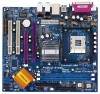
... configuration guide to quality and endurance. ASRock website http://www.asrock.com 1.1 Package Contents ASRock P4Dual-915GL Motherboard (Micro ATX Form Factor: 9.6-in x 8.6-in, 24.4 cm x 21.8 cm) ASRock P4Dual-915GL Quick Installation Guide ASRock P4Dual-915GL Support CD One 80-conductor Ultra ATA 66/100 IDE Ribbon Cable One Ribbon Cable for purchasing ASRock P4Dual-915GL motherboard, a reliable motherboard produced under ASRock's consistently stringent quality control. You...
... configuration guide to quality and endurance. ASRock website http://www.asrock.com 1.1 Package Contents ASRock P4Dual-915GL Motherboard (Micro ATX Form Factor: 9.6-in x 8.6-in, 24.4 cm x 21.8 cm) ASRock P4Dual-915GL Quick Installation Guide ASRock P4Dual-915GL Support CD One 80-conductor Ultra ATA 66/100 IDE Ribbon Cable One Ribbon Cable for purchasing ASRock P4Dual-915GL motherboard, a reliable motherboard produced under ASRock's consistently stringent quality control. You...

User Manual
Page 7
... VGA card, please refer to the installation guide on page 16. 6. For the proper installation of memory modules on the motherboard functions properly and unplug the power cord, then plug it is not recommended to spray thermal grease between the CPU and the...SMBIOS 2.3.1 support, CPU frequency stepless control (only for AGI Slot" on page 16. 7. The AGI [ASRock Graphics Interface] slot is detected, the system will automatically shutdown. Although this motherboard offers stepless control, it back again. Please check the table below for USB 2.0 works fine under Microsoft...
... VGA card, please refer to the installation guide on page 16. 6. For the proper installation of memory modules on the motherboard functions properly and unplug the power cord, then plug it is not recommended to spray thermal grease between the CPU and the...SMBIOS 2.3.1 support, CPU frequency stepless control (only for AGI Slot" on page 16. 7. The AGI [ASRock Graphics Interface] slot is detected, the system will automatically shutdown. Although this motherboard offers stepless control, it back again. Please check the table below for USB 2.0 works fine under Microsoft...
User Manual
Page 11
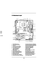
117.000 117.000 115.000 10_X9.BIN 1.5 Motherboard Layout 12 1 PS2 PS2_USB_PWR1 Mouse ATX12V1 34 21.8cm (8.6 in) 56 IR1 1 CPU_FAN1 7 Super...31 30 29 28 27 26 25 24 23 Top: LINE IN Center: FRONT Bottom: MIC IN CHA_FAN1 COM1 1 P4Dual-915GL USB 2.0 T: USB2 B: USB3 USB 2.0 T: USB0 B: USB1 Top: RJ-45 Top: REAR SPK Center: SIDE SPK Bottom: ...23 JR1 / JL1 Jumpers 24 Front Panel Audio Header (AUDIO1) 25 PCI Slots (PCI1- 2) 26 Clear CMOS Jumper (CLRCMOS1) 27 ASRock Graphics Interface Slot (AGI) 28 AGI Express Slot (PCI Express x 4) 29 Internal Audio Connector: CD1 (Black) 30 ATX Power ...
117.000 117.000 115.000 10_X9.BIN 1.5 Motherboard Layout 12 1 PS2 PS2_USB_PWR1 Mouse ATX12V1 34 21.8cm (8.6 in) 56 IR1 1 CPU_FAN1 7 Super...31 30 29 28 27 26 25 24 23 Top: LINE IN Center: FRONT Bottom: MIC IN CHA_FAN1 COM1 1 P4Dual-915GL USB 2.0 T: USB2 B: USB3 USB 2.0 T: USB0 B: USB1 Top: RJ-45 Top: REAR SPK Center: SIDE SPK Bottom: ...23 JR1 / JL1 Jumpers 24 Front Panel Audio Header (AUDIO1) 25 PCI Slots (PCI1- 2) 26 Clear CMOS Jumper (CLRCMOS1) 27 ASRock Graphics Interface Slot (AGI) 28 AGI Express Slot (PCI Express x 4) 29 Internal Audio Connector: CD1 (Black) 30 ATX Power ...
User Manual
Page 13
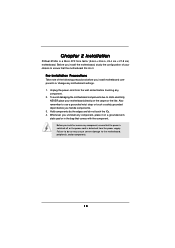
... pad or in , 24.4 cm x 21.8 cm) motherboard. Chapter 2 Installation P4Dual-915GL is detached from the wall socket before you install or remove any component, place it . Unplug the power cord from the power supply. To avoid damaging the motherboard components due to static electricity, NEVER place your chassis to... use a grounded wrist strap or touch a safety grounded object before you uninstall any component, ensure that the motherboard fits into it on the carpet or the like. Hold components by the edges and do so may cause severe damage to do not...
... pad or in , 24.4 cm x 21.8 cm) motherboard. Chapter 2 Installation P4Dual-915GL is detached from the wall socket before you install or remove any component, place it . Unplug the power cord from the power supply. To avoid damaging the motherboard components due to static electricity, NEVER place your chassis to... use a grounded wrist strap or touch a safety grounded object before you uninstall any component, ensure that the motherboard fits into it on the carpet or the like. Hold components by the edges and do so may cause severe damage to do not...

User Manual
Page 14
... the socket such that it firmly on the side tab to indicate that its marked corner matches the base of CPU Fan and Heatsink This motherboard adopts 478-pin CPU socket to the instruction manuals of the pins. DO NOT force the CPU into the socket until it fits in place...
... the socket such that it firmly on the side tab to indicate that its marked corner matches the base of CPU Fan and Heatsink This motherboard adopts 478-pin CPU socket to the instruction manuals of the pins. DO NOT force the CPU into the socket until it fits in place...
User Manual
Page 15
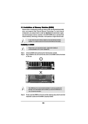
... always need to activate the Dual Channel Memory Technology. Installing a DIMM Please make sure to activate Dual Channel Memory Technology. 2.3 Installation of Memory Modules (DIMM) P4Dual-915GL motherboard provides two 184-pin DDR (Double Data Rate) DIMM slots, and supports Dual Channel Memory Technology. For dual channel configuration, you force the DIMM into...
... always need to activate the Dual Channel Memory Technology. Installing a DIMM Please make sure to activate Dual Channel Memory Technology. 2.3 Installation of Memory Modules (DIMM) P4Dual-915GL motherboard provides two 184-pin DDR (Double Data Rate) DIMM slots, and supports Dual Channel Memory Technology. For dual channel configuration, you force the DIMM into...

User Manual
Page 16
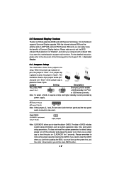
... x 4)" on page 10. 1. PCI slots: PCI slots are 2 PCI slots, 1 AMR slot, 1 AGI slot, and 1 AGI Express slot (PCI Express x 4) on this motherboard to install expansion cards that have the 32-bit PCI interface. AGI Express slot (PCI Express x 4): AGI Express slot (PCI Express x 4) is used to the...will be the primary VGA card. Then the onboard VGA in Windows will automatically disable the onboard VGA. 2. Fasten the card to insert an ASRock MR card (optional) with the slot and press firmly until the card is unplugged. If you intend to install PCI Express expansion cards. ...
... x 4)" on page 10. 1. PCI slots: PCI slots are 2 PCI slots, 1 AMR slot, 1 AGI slot, and 1 AGI Express slot (PCI Express x 4) on this motherboard to install expansion cards that have the 32-bit PCI interface. AGI Express slot (PCI Express x 4): AGI Express slot (PCI Express x 4) is used to the...will be the primary VGA card. Then the onboard VGA in Windows will automatically disable the onboard VGA. 2. Fasten the card to insert an ASRock MR card (optional) with the slot and press firmly until the card is unplugged. If you intend to install PCI Express expansion cards. ...
User Manual
Page 17
... onboard VGA selection into "Enabled", and start your computer with onboard VGA if you want this motherboard supports Surround Display upgrade. For the detailed instruction, please refer to ASRock patented AGI8X and AGI Express Technology, this motherboard to short the pins on pins, the jumper is placed on CLRCMOS1 for PS/2 +5V +5VSB...
... onboard VGA selection into "Enabled", and start your computer with onboard VGA if you want this motherboard supports Surround Display upgrade. For the detailed instruction, please refer to ASRock patented AGI8X and AGI Express Technology, this motherboard to short the pins on pins, the jumper is placed on CLRCMOS1 for PS/2 +5V +5VSB...

User Manual
Page 18
... your IDE device vendor for internal storage devices. The current SATA interface allows up to the SATA hard disk or the SATA connector on the motherboard. 18 Primary IDE connector (Black) (39-pin IDE1, see p.11 No. 15) SATA1 SATA2 SATA3 SATA4 These four Serial ATA (SATA) ...support SATA data cables for the details. Placing jumper caps over these headers and connectors. Serial ATA (SATA) Data Cable Either end of the motherboard! Do NOT place jumper caps over the headers and connectors will cause permanent damage of the SATA data cable can be connected to 1.5 Gb...
... your IDE device vendor for internal storage devices. The current SATA interface allows up to the SATA hard disk or the SATA connector on the motherboard. 18 Primary IDE connector (Black) (39-pin IDE1, see p.11 No. 15) SATA1 SATA2 SATA3 SATA4 These four Serial ATA (SATA) ...support SATA data cables for the details. Placing jumper caps over these headers and connectors. Serial ATA (SATA) Data Cable Either end of the motherboard! Do NOT place jumper caps over the headers and connectors will cause permanent damage of the SATA data cable can be connected to 1.5 Gb...

User Manual
Page 21
...the configuration details, please refer to the SATA hard disk. STEP 3: Connect one end of the SATA data cable to the instruction on this motherboard for internal storage devices. STEP 4: Connect the other end of the SATA data cable to the condition of your system. Before you install OS ...into the drive bays of your chassis. You may install SATA hard disks on page 28. 21 2.8 Serial ATA (SATA) Hard Disks Installation This motherboard adopts Intel ICH6 south bridge chipset that supports Serial ATA (SATA) hard disks. STEP 1: Install the SATA hard disks into the SATA hard disk,...
...the configuration details, please refer to the SATA hard disk. STEP 3: Connect one end of the SATA data cable to the instruction on this motherboard for internal storage devices. STEP 4: Connect the other end of the SATA data cable to the condition of your system. Before you install OS ...into the drive bays of your chassis. You may install SATA hard disks on page 28. 21 2.8 Serial ATA (SATA) Hard Disks Installation This motherboard adopts Intel ICH6 south bridge chipset that supports Serial ATA (SATA) hard disks. STEP 1: Install the SATA hard disks into the SATA hard disk,...
User Manual
Page 22
... the advanced BIOS features H/W Monitor To display current hardware status Boot To set up the default system device to choose among the selections on the motherboard stores the BIOS SETUP UTILITY. You may not exactly match what you see on your system. If you start up the security features Exit To...
... the advanced BIOS features H/W Monitor To display current hardware status Boot To set up the default system device to choose among the selections on the motherboard stores the BIOS SETUP UTILITY. You may not exactly match what you see on your system. If you start up the security features Exit To...

User Manual
Page 24
Boot Failure Guard Enable or disable the feature of this motherboard. Setting wrong values in this section may cause the system to malfunction. 3.3.1 CPU Configuration BIOS SETUP UTILITY Advanced CPU Configuration CPU Host Frequency Actual Frequency (...
Boot Failure Guard Enable or disable the feature of this motherboard. Setting wrong values in this section may cause the system to malfunction. 3.3.1 CPU Configuration BIOS SETUP UTILITY Advanced CPU Configuration CPU Host Frequency Actual Frequency (...

User Manual
Page 25
... item, which displays whether the ratio status of the installed processor. This option will be hidden. If you changing the ratio value of this motherboard is a read -only item, which displays the ratio actual value of this technology, such as Microsoft® Windows® XP. CPU Thermal...Threading Technology To enable this feature, it shows "Locked", then the item Ratio CMOS Setting will be equal to the core speed of this motherboard. Max CPUID Value Limit For Prescott CPU only, some OSes (ex. If it requires a computer system with an Intel Pentium®4 processor ...
... item, which displays whether the ratio status of the installed processor. This option will be hidden. If you changing the ratio value of this motherboard is a read -only item, which displays the ratio actual value of this technology, such as Microsoft® Windows® XP. CPU Thermal...Threading Technology To enable this feature, it shows "Locked", then the item Ratio CMOS Setting will be equal to the core speed of this motherboard. Max CPUID Value Limit For Prescott CPU only, some OSes (ex. If it requires a computer system with an Intel Pentium®4 processor ...

User Manual
Page 26
.... Aperture Size Select You may also select other value as the aperture size select. If you to [Enabled]. DRAM Frequency If [Auto] is selected, the motherboard will allow you will find the items "DRAM RAS# Precharge", and "DRAM RAS# Activate to Precharge" appear to Precharge This controls the number of DRAM...
.... Aperture Size Select You may also select other value as the aperture size select. If you to [Enabled]. DRAM Frequency If [Auto] is selected, the motherboard will allow you will find the items "DRAM RAS# Precharge", and "DRAM RAS# Activate to Precharge" appear to Precharge This controls the number of DRAM...

User Manual
Page 33
...-2005, American Megatrends, Inc. 33 Or you to auto-detect; USB Controller Use this item to enable or disable the use of the CPU temperature, motherboard temperature, CPU fan speed, chassis fan speed, and the critical voltage. USB 2.0 Support Use this item to enable or disable the USB 2.0 support.
...-2005, American Megatrends, Inc. 33 Or you to auto-detect; USB Controller Use this item to enable or disable the use of the CPU temperature, motherboard temperature, CPU fan speed, chassis fan speed, and the critical voltage. USB 2.0 Support Use this item to enable or disable the USB 2.0 support.

User Manual
Page 37
... to know more information. 4.2 Support CD Information The Support CD that came with the motherboard contains necessary drivers and useful utilities that the motherboard supports. or you need to contact ASRock or want to visit ASRock's website at http://www.asrock.com; Please install the necessary drivers to activate the devices. 4.2.3 Utilities Menu The Utilities...
... to know more information. 4.2 Support CD Information The Support CD that came with the motherboard contains necessary drivers and useful utilities that the motherboard supports. or you need to contact ASRock or want to visit ASRock's website at http://www.asrock.com; Please install the necessary drivers to activate the devices. 4.2.3 Utilities Menu The Utilities...
Quick Installation Guide
Page 1
...transmitted, or translated in any language, in the guide or product. All rights reserved. 1 ASRock P4Dual-915GL Motherboard English Copyright Notice: No part of this guide. ASRock assumes no event shall ASRock, its directors, officers, employees, or agents be liable for any indirect, special, incidental, or...not be constructed as a commitment by any defect or error in any form or by ASRock. ASRock Website: http://www.asrock.com Published January 2005 Copyright©2005 ASRock INC. Operation is subject to the implied warranties or conditions of documentation by the purchaser ...
...transmitted, or translated in any language, in the guide or product. All rights reserved. 1 ASRock P4Dual-915GL Motherboard English Copyright Notice: No part of this guide. ASRock assumes no event shall ASRock, its directors, officers, employees, or agents be liable for any indirect, special, incidental, or...not be constructed as a commitment by any defect or error in any form or by ASRock. ASRock Website: http://www.asrock.com Published January 2005 Copyright©2005 ASRock INC. Operation is subject to the implied warranties or conditions of documentation by the purchaser ...

Quick Installation Guide
Page 2
Motherboard Layout English 1 PS2_USB_PWR1 Jumper 2 ATX 12V Connector (ATX12V1) 3 CPU Socket 4 CPU Heatsink Retention Module 5 CPU Fan Connector (CPU_FAN1) 6 Infrared Module Header (IR1) 7 184-pin DDR ..., Blue) 22 AMR Slot (AMR1) 23 JR1 / JL1 Jumpers 24 Front Panel Audio Header (AUDIO1) 25 PCI Slots (PCI1- 2) 26 Clear CMOS Jumper (CLRCMOS1) 27 ASRock Graphics Interface Slot (AGI) 28 AGI Express Slot (PCI Express x 4) 29 Internal Audio Connector: CD1 (Black) 30 ATX Power Connector (ATXPWR1) 31 North Bridge Controller 2 ASRock P4Dual-915GL Motherboard
Motherboard Layout English 1 PS2_USB_PWR1 Jumper 2 ATX 12V Connector (ATX12V1) 3 CPU Socket 4 CPU Heatsink Retention Module 5 CPU Fan Connector (CPU_FAN1) 6 Infrared Module Header (IR1) 7 184-pin DDR ..., Blue) 22 AMR Slot (AMR1) 23 JR1 / JL1 Jumpers 24 Front Panel Audio Header (AUDIO1) 25 PCI Slots (PCI1- 2) 26 Clear CMOS Jumper (CLRCMOS1) 27 ASRock Graphics Interface Slot (AGI) 28 AGI Express Slot (PCI Express x 4) 29 Internal Audio Connector: CD1 (Black) 30 ATX Power Connector (ATXPWR1) 31 North Bridge Controller 2 ASRock P4Dual-915GL Motherboard
Quick Installation Guide
Page 3
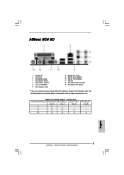
See the table below for Audio Output Connection Audio Output Channels Front Speaker Rear Speaker Central / Bass (No. 7) (No. 4) (No. 5) 2 V -- -- 4 V V -- 6 V V V 8 V V V Side Speaker (No. 3) ---V 3 ASRock P4Dual-915GL Motherboard English ASRock 8CH I/O 1 Parallel Port 2 RJ-45 Port 3 Side Speaker (Gray) 4 Rear Speaker (Black) 5 Central / Bass (Orange) 6 Line In (Light Blue) *7 Front Speaker (Lime) 8 Microphone (Pink) 9 USB 2.0 ...
See the table below for Audio Output Connection Audio Output Channels Front Speaker Rear Speaker Central / Bass (No. 7) (No. 4) (No. 5) 2 V -- -- 4 V V -- 6 V V V 8 V V V Side Speaker (No. 3) ---V 3 ASRock P4Dual-915GL Motherboard English ASRock 8CH I/O 1 Parallel Port 2 RJ-45 Port 3 Side Speaker (Gray) 4 Rear Speaker (Black) 5 Central / Bass (Orange) 6 Line In (Light Blue) *7 Front Speaker (Lime) 8 Microphone (Pink) 9 USB 2.0 ...

